
 My Inquiry
 My Account


NXP Semiconductors KTY83/110,153
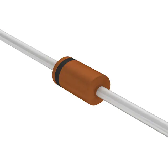
- Part No.:
- KTY83/110,153
- Manufacturer:
- NXP Semiconductors
- Category:
- PTC Thermistors
- Package:
- DO-204AG, DO-34, Axial
- Datasheet:
-
 KTY83/110,153.pdf
- Description:
- SENSOR PTC 1KOHM DO34
- Quantity:
- Payment:

- Shipping:

Inventory:3,806
Please send an inquiry. Send us your inquiry, and we will respond immediately.
Product details
Overview
KTY83/110,153 from NXP Semiconductors is a silicon-based positive temperature coefficient (PTC) temperature sensor in a hermetically sealed SOD68 (DO-34) axial-leaded glass package, with nominal resistance R25 = 990–1010 Ω at 25 °C, temperature coefficient TC = 0.76 %/K, and operating range from −55 °C to +175 °C. It delivers fail-safe behavior and near-linear resistance vs. temperature response for analog temperature monitoring in automotive engine control units.
For engineers reviewing the KTY83/110,153 datasheet, KTY83/110,153 pinout, KTY83/110,153 application, or KTY83/110,153 equivalent, this page provides verified pin functions, resistance-temperature mapping, thermal time constants in air/liquid, long-term drift spec (≤1 Ω after 10,000 h at 175 °C), and direct alternatives for industrial thermal sensing designs requiring high stability and PTC safety margin.
Technical Context
The KTY83/110,153 operates as a two-terminal passive resistive sensor: its anode and cathode terminals form a current-driven PTC element where resistance increases monotonically with ambient temperature. Its virtually linear R(T) curve-characterized by R−55/R25 = 0.49–0.51 and R100/R25 = 1.65–1.69-enables direct analog voltage division without complex linearization circuitry.
Thermal response is defined by τth = 20 s in still air, 1 s in still liquid, and 0.5 s in flowing liquid, supporting rapid thermal feedback in coolant or oil monitoring. Maximum continuous sensor current Isen(cont) is limited to 10 mA at 25 °C but derates to 2 mA at 175 °C to prevent self-heating error beyond ±1.31 K at 25 °C.
Key Specifications
| Parameter | Value and Actual Design Meaning |
|---|---|
| R25 | 990–1010 Ω at 25 °C; sets baseline gain and sensitivity of voltage-divider interface circuits |
| TC | 0.76 %/K; defines slope of resistance change per degree, enabling predictable analog scaling |
| R100/R25 | 1.65–1.69; confirms stable PTC ratio across 75 K span, critical for calibration traceability |
| τth (liquid) | 1 s in still liquid; ensures <2% thermal lag in engine oil or transmission fluid temperature tracking |
| Isen(cont) | 10 mA max at 25 °C; limits self-heating to <0.1 K error under typical 1 mA bias condition |
| ∆R25 drift | ≤1 Ω after 10,000 h at 175 °C; guarantees resistance stability in under-hood applications |
| Tamb range | −55 °C to +175 °C; supports operation in extreme environments including exhaust proximity |
Pinout & Package
Package: SOD68 (DO-34), hermetically sealed axial-leaded glass package with 2.54 mm lead spacing and 3.04 mm maximum body diameter.
| Pin/Terminal | Circuit Role | Design Meaning |
|---|---|---|
| 1 | Cathode (k) | Reference terminal for current sourcing; reverse-biased polarity prevents unintended conduction |
| 2 | Anode (a) | Current input terminal; forms PTC sensing path when biased with 1 mA constant current |
Key Features
| Feature | Design Value |
|---|---|
| Fail-safe PTC behavior | Resistance rises with temperature-detects overtemp as open-circuit-like signal increase, not failure mode |
| Virtually linear R(T) | ±1.31 K max error at 25 °C and ≤±7.19 K at 150 °C enables 1st-order compensation in MCU ADC firmware |
| Long-term stability | ≤1 Ω resistance drift after 10,000 h at 175 °C ensures calibration retention in 10+ year automotive deployments |
| High-temp capability | Rated to +175 °C ambient-validated for placement near turbochargers, exhaust manifolds, and transmission housings |
| Hermetic SOD68 seal | Prevents moisture ingress and corrosion in humid or chemically aggressive under-hood environments |
Applications
| Engine Coolant Monitoring | Transmission Fluid Sensing |
|---|---|
Use Scenario: Real-time measurement of coolant temperature in ICE powertrains for fan control, cold-start enrichment, and overheat protection. IC Role / Device Role / Timing Role: Two-terminal resistive sensor interfaced to MCU ADC via precision current source and voltage divider. Use Value: ±1.31 K accuracy at 25 °C and R25 tolerance of ±10 Ω enable robust closed-loop thermal management without lookup table interpolation. |
Use Scenario: Continuous monitoring of automatic transmission fluid temperature to prevent overheating and optimize shift timing. IC Role / Device Role / Timing Role: Analog PTC element placed directly in fluid path; resistance read via 1 mA bias and ratiometric ADC conversion. Use Value: τth = 1 s in still liquid ensures <500 ms response to fluid temp transients, meeting ASAM MCD-2 MC timing requirements. |
| Exhaust Gas Recirculation (EGR) Valve Temp | Industrial Oven Chamber Control |
Use Scenario: Temperature feedback for EGR cooler inlet/outlet to regulate recirculated gas flow and reduce NOx emissions. IC Role / Device Role / Timing Role: High-temp PTC sensor mounted on EGR valve housing, exposed to >150 °C ambient during active duty cycles. Use Value: Stable operation up to +175 °C and ≤±7.19 K error at 150 °C ensures reliable thermal feedback despite thermal cycling stress. |
Use Scenario: Zone-specific temperature monitoring inside industrial batch ovens used for PCB curing and metal annealing. IC Role / Device Role / Timing Role: Axial-leaded SOD68 sensor embedded in oven wall insulation, wired to centralized PLC analog input module. Use Value: Hermetic glass package resists thermal shock and chemical vapors (e.g., flux residues, cleaning solvents), ensuring >15-year field life. |
Equivalent & Alternatives
The following parts are listed as comparable options for similar PTC temperature sensing applications.
| Alternative Part | Technical Difference | Application Difference | Selection Advice |
|---|---|---|---|
| KTY83/120 | R25 = 980–1020 Ω; TC identical; R−55/R25 = 0.49–0.51; same SOD68 package and pinout | Higher max R25 tolerance (±20 Ω vs. ±10 Ω) yields wider initial calibration spread | Select when system-level calibration tolerates ±20 Ω baseline variance and cost optimization is prioritized |
| KTY83/151 | R25 = 950–1000 Ω; TC identical; R−55/R25 = 0.49–0.51; same SOD68 package and pinout | Lower R25 range shifts voltage-divider output lower; requires ADC gain adjustment | Choose for legacy designs already calibrated to 950–1000 Ω range or where reduced self-heating at low bias currents is needed |
Compared with KTY83/110,153, KTY83/120 offers broader R25 tolerance for cost-sensitive volume production, while KTY83/151 provides lower baseline resistance for improved SNR in low-voltage microcontroller interfaces-neither is pin-compatible without recalibration due to R25 offset.
Availability
KTY83/110,153 is available at Aetrix Electronics and suitable for automotive engine control, industrial oven monitoring, and transmission thermal management requiring stable component supply across extended temperature ranges and long service life.
Supply support for KTY83/110,153 includes scheduled delivery planning, volume procurement assistance, BOM continuity management, traceable sourcing, and lifecycle availability coordination for OEM customers, industrial embedded developers, connected-device designers, and electronics production programs.
Manufacturer
NXP Semiconductors is a global semiconductor company headquartered in Eindhoven, Netherlands, specializing in secure connectivity solutions for automotive, industrial, and IoT applications.
The KTY83 series belongs to NXP's analog sensor product line, designed specifically for high-reliability, high-temperature PTC temperature sensing in harsh environments where fail-safe thermal feedback is mandatory.
FAQ
What is the maximum continuous operating current for KTY83/110,153 at 25 °C?
The maximum continuous sensor current Isen(cont) for KTY83/110,153 is 10 mA at Tamb = 25 °C. This limit ensures self-heating remains below 0.1 K under standard 1 mA bias conditions. At elevated temperatures-such as 175 °C-the rating drops to 2 mA to maintain accuracy and reliability. Exceeding these values risks permanent resistance drift or thermal damage. Always verify bias current against ambient temperature using the derating curve in the KTY83/110,153 datasheet.
How does the resistance of KTY83/110,153 change from −55 °C to +175 °C?
KTY83/110,153 exhibits a monotonic positive temperature coefficient: resistance decreases to 485–515 Ω at −55 °C (R−55/R25 = 0.49–0.51) and increases to 2449–2621 Ω at +175 °C. The R100/R25 ratio is 1.65–1.69, confirming consistent PTC behavior across the full range. This predictable progression allows direct use in voltage-divider circuits with minimal linearization-especially effective between 0 °C and 125 °C where temperature error stays within ±3.5 K.
Can KTY83/110,153 be used in flowing liquid environments?
Yes, KTY83/110,153 is qualified for use in flowing liquid with a thermal time constant τth of 0.5 s-enabling sub-second response to temperature transients in coolant or lubricant streams. Its hermetically sealed SOD68 glass package prevents moisture ingress and withstands mechanical vibration common in pump-fed systems. For optimal performance, mount with leads oriented perpendicular to flow direction to minimize turbulence-induced stress on the glass body.
What is the long-term resistance stability of KTY83/110,153 at high temperature?
KTY83/110,153 demonstrates ≤1 Ω resistance drift (∆R25) after 10,000 hours of continuous operation at 175 °C. This stability is validated per IEC 60134 limiting values and reflects the sensor's suitability for automotive under-hood applications with 15+ year service life expectations. The drift specification applies only under specified bias (Isen(cont) = 1 mA) and thermal cycling profiles-exceeding current or temperature ratings accelerates aging.
Is KTY83/110,153 compatible with standard DO-34 socket fixtures?
Yes, KTY83/110,153 uses the industry-standard SOD68 (DO-34) package with 2.54 mm lead spacing and 3.04 mm max body diameter, making it mechanically compatible with DO-34 test sockets, wave-solder pallets, and automated optical inspection (AOI) carriers. Its axial-leaded construction supports both through-hole assembly and manual prototyping. Ensure lead forming avoids bending within 1.5 mm of the glass body to prevent hermeticity loss.
KTY83/110,153 Specifications
- Product attributes
- Attribute value
- Manufacturer:
- NXP Semiconductors
- Series:
- KTY83
- Package/Case:
- DO-204AG, DO-34, Axial
- Packaging:
- Tape & Box (TB)
- Product Status:
- Obsolete
- Resistance @ 25°C:
- 1 kOhms
- Resistance Tolerance:
- -
- Operating Temperature:
- -55°C ~ 175°C
- Power - Max:
- -
- Mounting Type:
- Through Hole
- Grade:
- -
- Qualification:
- -
- Supplier Device Package:
- DO-34
KTY83/110,153 FAQ
1.How can I place an order for KTY83/110,153 through Aetrix?
Please submit a Request for Quotation (RFQ) for KTY83/110,153 on Aetrix. Our sales agent will provide a competitive quotation and guide you through the order confirmation once you accept the terms.
2.Are the price and stock information for KTY83/110,153 reliable?
The price and inventory of KTY83/110,153 are updated periodically and may fluctuate due to market conditions. Stock and pricing data are typically refreshed every 24 hours. Quotation validity for KTY83/110,153 is usually 5 days.
3.What payment methods are accepted for KTY83/110,153?
We accept Wire Transfer, PayPal, Credit Card, Western Union, MoneyGram, and Escrow for KTY83/110,153 transactions.
Note: Certain payment methods may incur a processing fee.
4.How is shipping managed for KTY83/110,153?
KTY83/110,153 orders can be shipped via leading logistics carriers, including DHL, UPS, FedEx, TNT, or Registered Mail.
Once your KTY83/110,153 order is processed, you will receive an email with the shipment details and tracking number.
Note: Tracking information may take up to 24 hours to appear. Express delivery typically takes 3–5 business days.
5.How can I obtain technical support or documentation for KTY83/110,153?
For technical support, including KTY83/110,153 datasheets, pinout diagrams, or application guidance, please contact our engineering support team. They can provide detailed documentation and assistance for your KTY83/110,153 requirements.
6.How does Aetrix verify that KTY83/110,153 is sourced from the original manufacturer or authorized distributors?
All KTY83/110,153 products on Aetrix are procured from qualified distributors and authorized channels. Our dedicated quality assurance team conducts strict verification, including traceability checks and, if necessary, third-party testing. This ensures that KTY83/110,153 meets industry standards.
7.What is the process for return or replacement of KTY83/110,153?
All KTY83/110,153 units undergo pre-shipment inspection (PSI). If there is an issue with KTY83/110,153, returns or replacements are accepted under the following conditions:
1.Quantity discrepancies, incorrect items, or visible external defects (such as breakage or corrosion), acknowledged by Aetrix.
2.The issue is reported within 90 days of delivery.
3.The KTY83/110,153 part is unused and in its original packaging.
Return procedure for KTY83/110,153:
1.Submit a request within 90 days.
2.Obtain a Return Material Authorization (RMA) from Aetrix.
KTY83/110,153 Tags
.jpg)
-
B59421A0075A062
EPCOS - TDK Electronics
-
B59641A0105A062
EPCOS - TDK Electronics

-
B59721A0100A062
EPCOS - TDK Electronics
-
B59701A0100A062
EPCOS - TDK Electronics
-
TFPT0603L1001FM
Vishay Dale
.jpg)
-
TFPT0805L1000FV
Vishay Dale
-
TFPT0603L1001FV
Vishay Dale
.jpg)
-
TFPT1206L1002FV
Vishay Dale
-
B59052D1090A040
EPCOS - TDK Electronics
-
102PS1G
Littelfuse Inc.
-
B59100M1100A070
EPCOS - TDK Electronics
-
STS110003CHIP
Cantherm
Tech Hub

A practical engineering guide to 3.3V and 5V logic compatibility, input thresholds, resistor dividers, translator ICs, MOSFET level shifting, I2C pull-ups, timing limits and power-sequencing risks.

The 74HC595 uses push-pull logic outputs, while the TPIC6B595 uses 50 V open-drain DMOS sinks for higher-power loads. This guide compares timing, current limits, 3.3 V interfacing, load wiring, thermal…

The 74HC595 converts serial data into eight stable parallel outputs. This guide covers pin functions, shift and storage timing, OE and MR behavior, drive-current limits, cascading, voltage compatibilit…

A technical comparison of level-sensitive latches and edge-triggered flip-flops, covering timing windows, setup and hold limits, master–slave operation, time borrowing, race-through, HDL inference and…

A D latch stores one bit while Enable controls when data can pass. This reference covers gate-level operation, truth tables, transparency, setup and hold timing, LE versus OE, common ICs and practical …

An SR latch stores one bit through cross-coupled feedback. This engineering reference covers NOR and NAND implementations, truth tables, forbidden-state recovery, gated operation, switch debouncing, fa…

Latch circuits retain one bit through feedback. This technical reference covers SR and D latches, truth tables, transparency, timing limits, latch-versus-flip-flop behavior, applications and common log…

An engineering guide to LED driver operation, constant-current and constant-voltage outputs, linear and switching topologies, dimming, IC selection, calculations, replacement compatibility, and fault c…

Operational amplifier guide covering op amp basics, feedback, ideal vs real op amps, common configurations, buffer circuits, offset, bias current, gain-bandwidth, slew rate, rail-to-rail limits and sel…

Jumper cables guide covering safe connection order, red and black clamp placement, final ground connection, cable gauge, length, clamp quality, copper vs CCA cables, jump starter comparison and battery…


