
 My Inquiry
 My Account


STMicroelectronics L294
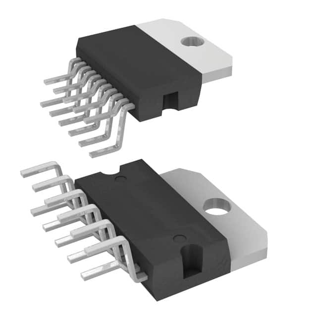
- Part No.:
- L294
- Manufacturer:
- STMicroelectronics
- Package:
- Multiwatt-11 (Vertical, Bent and Staggered Leads)
- Datasheet:
-
 L294.pdf
- Description:
- IC PWR DRVR BIPLR 1:2 11MULTWATT
- Quantity:
- Payment:

- Shipping:

Inventory:2,232
Please send an inquiry. Send us your inquiry, and we will respond immediately.
Product details
Overview
L294 from STMicroelectronics is a monolithic switch-mode solenoid driver IC designed for high-current, fast-switching applications including print head hammer and needle actuation in dot-matrix printers and electronic typewriters. It supports up to 50 V supply voltage, delivers peak output current of 4.5 A, features latched diagnostic output for short-circuit detection, and operates with TTL-compatible enable and input logic.
For engineers reviewing the L294 datasheet, L294 pinout, L294 application, or L294 equivalent, this device is selected for precision transconductance-controlled solenoid drive where thermal shutdown, overdriving protection, and output short-circuit diagnostics (to ground, supply, or across load) are critical design requirements.
Technical Context
The L294 functions as a transconductance amplifier with input voltage (Vi, pin 7) directly controlling peak output current (Ip) via external sensing resistor Rs (0.2 Ω typical), delivering 1 A/V gain at Vi ≥ 600 mV. Its operation relies on internal op-amp/OTA signal conditioning, comparator-based timing control, and RC network (pin 8) for on-time limiting.
It integrates dual-output switching stages (source and sink), latched open-collector diagnostic output (pin 5), thermal shutdown with ~20 °C hysteresis, and independent overdriving protection triggered by capacitor C2 (pin 3) charged at constant current when ENABLE is low.
Key Specifications
| Parameter | Value and Actual Design Meaning |
|---|---|
| Supply Voltage (Vs) | 12–46 V operative range; enables direct integration into 24 V/48 V industrial solenoid systems without external regulation. |
| Peak Output Current (Ip) | 4.5 A repetitive; sufficient to drive high-force printer hammers and electromagnetic actuators requiring fast rise/fall times. |
| Transconductance (gm) | 1 A/V at Vi ≥ 600 mV with Rs = 0.2 Ω; provides linear, voltage-programmable current control for precise solenoid stroke timing. |
| VSAT,H + VSAT,L | 4.5 V at Ip = 4 A; limits conduction loss and junction heating during sustained drive cycles. |
| Rth-j-case | 3 °C/W maximum; supports 25 W total power dissipation at Tcase = 75 °C in Multiwatt11 package with heatsink interface. |
| Diagnostic Output | Latched open-collector (pin 5); asserts low when source/sink short detected (Isource > 5 A or VSENS > 1 V), enabling fault logging without microcontroller polling. |
Pinout & Package
The L294 is housed in an 11-lead Multiwatt® plastic power package with exposed backplate for thermal conduction. Pin numbering follows top-view layout per STMicroelectronics datasheet (Doc ID 2173, Rev 3, Sept 2003).
| Pin/Terminal | Circuit Role | Design Meaning |
|---|---|---|
| 1 (Vs) | Main power supply input | Accepts up to 50 V DC; connects to high-current solenoid supply rail with local decoupling. |
| 3 (C2) | Overdriving protection timer capacitor | External capacitor sets fixed off-time limit (tmax = K·C2); grounding disables protection. |
| 4 (VSS) | Logic supply voltage | 4.5–7 V digital supply for internal logic and DIAG flip-flop; must be stable and decoupled. |
| 5 (DIAG) | Latched diagnostic output | Open-collector output pulled low during short-circuit fault; requires external pull-up to VSS. |
| 7 (Vi) | Transconductance input | Analog control voltage (0.6–4 V) setting peak load current; referenced to GND, not Vs. |
| 8 (RC) | Timing network node | Connects to external R1/C1; controls recirculation time t1 and minimum on-time via OTA charging. |
| 9 (ENABLE) | Active-low TTL enable | Drives both source/sink stages; low = active; rising edge resets overdriving timer (pin 3). |
| 10 (VSENS) | Current sense input | Monitors voltage across external Rs (0.2 Ω typical); triggers short-circuit shutdown if >1 V. |
Key Features
| Feature | Design Value |
|---|---|
| Latched diagnostic output | Pin 5 remains low after short-circuit detection until ENABLE toggles, enabling reliable fault capture in burst-driven systems. |
| Programmable peak current | Linear 1 A/V transconductance (Vi ≥ 600 mV) allows precise solenoid force/stroke tuning without current-sense amplifier redesign. |
| Integrated overdriving protection | Capacitor-timed disable (K·C2) prevents thermal runaway during stuck-enable conditions-resettable via ENABLE high pulse. |
| Dual-stage switching (source + sink) | Enables bidirectional current control and fast turn-off via diode recirculation (D1/D2), reducing mechanical bounce in impact printers. |
| Thermal shutdown with hysteresis | Turns off outputs above safe junction temperature and re-enables only after ~20 °C cooldown, preventing oscillatory tripping under marginal heatsinking. |
Applications
| Dot-Matrix Printer Hammer Drive | Electronic Typewriter Needle Actuator |
|---|---|
Use Scenario: Driving electromagnetic hammers that strike pins against inked ribbon to form characters on paper. IC Role / Device Role / Timing Role: Transconductance-controlled current source regulating hammer impact force and dwell time via Vi and ENABLE timing. Use Value: Enables consistent character density and reduced mechanical wear through repeatable 4.5 A peak current and <255 µs rise time. | Use Scenario: Controlling solenoid-driven typebars or levers that move individual letter elements onto platen. IC Role / Device Role / Timing Role: High-speed sink/source driver managing bidirectional coil current to position and retract type elements. Use Value: Delivers fast turn-off (<174 µs fall time) and recirculation path control, minimizing residual magnetism and improving typing speed. |
| Industrial Solenoid Valve Control | Automated Test Equipment (ATE) Actuators |
Use Scenario: Energizing 24 V/48 V solenoid valves in pneumatic/hydraulic control panels requiring robust fault reporting. IC Role / Device Role / Timing Role: Protected high-side/low-side driver with integrated short-circuit diagnostics and thermal management. Use Value: Eliminates need for external current monitors and discrete protection circuits-DIAG output directly interfaces to PLC fault inputs. | Use Scenario: Driving precision positioning solenoids in automated test fixtures for connector mating/unmating or probe actuation. IC Role / Device Role / Timing Role: Voltage-programmable current driver ensuring repeatable actuation force across production units. Use Value: Tight transconductance tolerance (±5% at Vi = 1 V) ensures consistent mechanical response without per-unit calibration. |
Equivalent & Alternatives
The following parts are listed as comparable options for similar solenoid driver applications.
| Alternative Part | Technical Difference | Application Difference | Selection Advice |
|---|---|---|---|
| STSPIN250 | Integrated MOSFETs, 3.6 A max, SPI interface, no latched DIAG, lower voltage (45 V max) | Requires microcontroller for configuration; lacks analog Vi control and hardware latch | Preferred for digitally controlled, space-constrained designs where programmability outweighs analog simplicity |
| TLE5206-2G | High-side only, 5 A, integrated current sense, no transconductance mode, no latched fault output | Designed for automotive valve control; lacks sink stage and Vi-based current programming | Selected when single-direction drive suffices and ASIL-B compliance is required |
Compared with STSPIN250 and TLE5206-2G, the L294 uniquely combines analog transconductance control, dual-source/sink topology, and hardware-latched diagnostics-making it irreplaceable in legacy impact-printer and analog-timed solenoid systems where deterministic, self-contained fault signaling is mandatory.
Availability
L294 is available at Aetrix Electronics and suitable for dot-matrix printer manufacturing, electronic typewriter repair, and industrial solenoid valve control requiring stable component supply despite end-of-life status.
Supply support for L294 includes scheduled delivery planning, volume procurement assistance, BOM continuity management, traceable sourcing, and lifecycle availability coordination for OEM customers, industrial embedded developers, connected-device designers, and electronics production programs.
Manufacturer
STMicroelectronics is a global semiconductor leader headquartered in Geneva, Switzerland, specializing in power management, analog, and motor control ICs for industrial and automotive markets.
The L294 belongs to ST's legacy high-voltage power driver product line, engineered specifically for electromechanical actuation in office automation equipment where reliability under repetitive high-current transients was paramount.
FAQ
What is the minimum input voltage (Vi) required to activate the L294 output?
The L294 begins operating only when Vi exceeds 450 mV; below this threshold, output remains disabled. Stable transconductance behavior (1 A/V) is guaranteed only above 600 mV, with linear response extending up to 4 V. Operation between 450–600 mV is not characterized and should be avoided in production designs.
How does the latched DIAG output reset after a short-circuit event?
The DIAG output remains latched low until the ENABLE pin is brought high, which resets the internal flip-flop. Simply removing power or toggling Vi does not clear the latch. The device must be re-enabled via ENABLE high-to-low transition after fault removal to restore normal operation.
Can the L294 drive inductive loads without external flyback diodes?
No. External fast-recovery diodes (e.g., 3 A, ≤200 ns trr) must be connected across the solenoid (D1/D2 in Fig. 2) to provide recirculation paths during turn-off. Omitting them causes destructive voltage spikes exceeding 50 V, triggering immediate overvoltage shutdown or permanent damage.
Is the L294 still manufactured, and what is its obsolescence status?
Yes, the L294 is marked "Obsolete Product(s)" in ST's official documentation (Doc ID 2173, Rev 3), indicating no new wafer starts. However, Aetrix Electronics maintains verified, traceable inventory from authorized legacy sources with full lot-level documentation and extended lifecycle support for continued production use.
L294 Specifications
- Product attributes
- Attribute value
- Manufacturer:
- STMicroelectronics
- Package/Case:
- Multiwatt-11 (Vertical, Bent and Staggered Leads)
- Series:
- -
- Packaging:
- Tube
- Product Status:
- Obsolete
- Switch Type:
- Relay, Solenoid Driver
- Number of Outputs:
- 2
- Ratio - Input:Output:
- 1:2
- Output Configuration:
- High Side
- Output Type:
- Bipolar
- Interface:
- On/Off
- Voltage - Load:
- 12V ~ 46V
- Voltage - Supply (Vcc/Vdd):
- 4.5V ~ 7V
- Current - Output (Max):
- -
- Rds On (Typ):
- -
- Input Type:
- Non-Inverting
- Features:
- -
- Fault Protection:
- Over Temperature
- Operating Temperature:
- -40°C ~ 150°C (TJ)
- Grade:
- -
- Qualification:
- -
- Mounting Type:
- Through Hole
- Supplier Device Package:
- Multiwatt-11 (Vertical, Bent and Staggered Leads)
L294 FAQ
1.How can I place an order for L294 through Aetrix?
Please submit a Request for Quotation (RFQ) for L294 on Aetrix. Our sales agent will provide a competitive quotation and guide you through the order confirmation once you accept the terms.
2.Are the price and stock information for L294 reliable?
The price and inventory of L294 are updated periodically and may fluctuate due to market conditions. Stock and pricing data are typically refreshed every 24 hours. Quotation validity for L294 is usually 5 days.
3.What payment methods are accepted for L294?
We accept Wire Transfer, PayPal, Credit Card, Western Union, MoneyGram, and Escrow for L294 transactions.
Note: Certain payment methods may incur a processing fee.
4.How is shipping managed for L294?
L294 orders can be shipped via leading logistics carriers, including DHL, UPS, FedEx, TNT, or Registered Mail.
Once your L294 order is processed, you will receive an email with the shipment details and tracking number.
Note: Tracking information may take up to 24 hours to appear. Express delivery typically takes 3–5 business days.
5.How can I obtain technical support or documentation for L294?
For technical support, including L294 datasheets, pinout diagrams, or application guidance, please contact our engineering support team. They can provide detailed documentation and assistance for your L294 requirements.
6.How does Aetrix verify that L294 is sourced from the original manufacturer or authorized distributors?
All L294 products on Aetrix are procured from qualified distributors and authorized channels. Our dedicated quality assurance team conducts strict verification, including traceability checks and, if necessary, third-party testing. This ensures that L294 meets industry standards.
7.What is the process for return or replacement of L294?
All L294 units undergo pre-shipment inspection (PSI). If there is an issue with L294, returns or replacements are accepted under the following conditions:
1.Quantity discrepancies, incorrect items, or visible external defects (such as breakage or corrosion), acknowledged by Aetrix.
2.The issue is reported within 90 days of delivery.
3.The L294 part is unused and in its original packaging.
Return procedure for L294:
1.Submit a request within 90 days.
2.Obtain a Return Material Authorization (RMA) from Aetrix.
L294 Tags

-
TPS22919DCKR
Texas Instruments

-
MIC2091-1YM5-TR
Microchip Technology

-
MIC2090-1YM5-TR
Microchip Technology

-
TPS22995RZFR
Texas Instruments

-
TPS22975DSGR
Texas Instruments

-
SIP32510DT-T1-GE3
Vishay Siliconix

-
ULN2003D1013TR
STMicroelectronics

-
MIC2005A-1YM5-TR
Microchip Technology

-
MIC2005A-1YM6-TR
Microchip Technology

-
TPS22916BYFPR
Texas Instruments

-
TPS22917DBVR
Texas Instruments

-
ULN2003APWR
Texas Instruments
Tech Hub

Operational amplifier guide covering op amp basics, feedback, ideal vs real op amps, common configurations, buffer circuits, offset, bias current, gain-bandwidth, slew rate, rail-to-rail limits and sel…

Jumper cables guide covering safe connection order, red and black clamp placement, final ground connection, cable gauge, length, clamp quality, copper vs CCA cables, jump starter comparison and battery…

LDO regulator guide covering low dropout voltage, power dissipation, thermal design, PSRR, output noise, capacitor stability, adjustable LDO circuits, LDO vs buck converter and datasheet selection chec…

Conditional Access Module guide covering CAM meaning, CI/CI+ interface, smart card authorization, DVB security workflow, TV and set-top box compatibility, internal electronics, ESD protection, connecto…

Guide to electronic component obsolescence covering EOL risk, PCN/PDN notices, last-time buy planning, replacement options, form-fit-function validation, counterfeit risk and BOM lifecycle management.

18650 battery guide covering lithium-ion cell basics, 3.6V/3.7V voltage, 4.2V charging, mAh and Wh capacity, protected cells, chargers, BMS, series-parallel packs, holders, welding and sourcing checks.…

Hall effect sensor guide covering working principle, linear and digital sensors, Arduino circuits, current sensing, speed detection, automotive applications, A3144 examples, signal filtering and datash…

Product Change Notification guide for electronic components, covering PCN meaning, PCN vs PDN/EOL, common change types, risk levels, form-fit-function review, engineering validation, BOM control, LTB/L…

A practical guide to blend door actuators, covering HVAC function, symptoms, location, AC and heater issues, reset and calibration, replacement cost, electrical diagnosis, compatibility checks, and rep…

Engineering guide to Raspberry Pi alternatives, covering chip-level differences, Orange Pi, ROCK, Jetson, Banana Pi, NanoPi, Compute Module, Pico, GPIO, camera, HAT compatibility, and replacement risks…


