
 My Inquiry
 My Account


STMicroelectronics L297/1
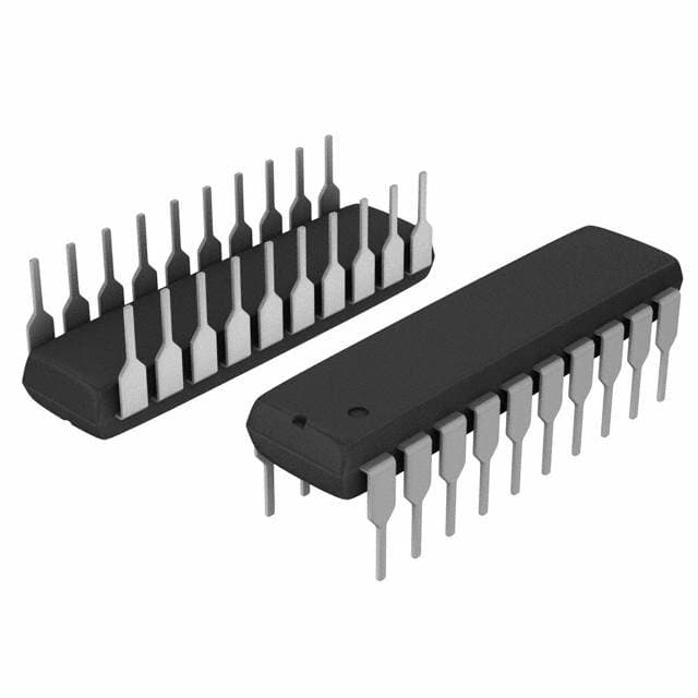
- Part No.:
- L297/1
- Manufacturer:
- STMicroelectronics
- Category:
- Motor Drivers, Controllers
- Package:
- 20-DIP (0.300", 7.62mm)
- Datasheet:
-
 L297/1.pdf
- Description:
- IC MOTOR DRVR BIPLR/UNIPLR 20DIP
- Quantity:
- Payment:

- Shipping:

Inventory:351
Please send an inquiry. Send us your inquiry, and we will respond immediately.
Product details
Overview
L297/1 from STMicroelectronics is a dedicated stepper motor controller IC for bipolar and unipolar two-phase/four-phase motors, supporting half-step, normal (two-phase-on), and wave (one-phase-on) drive modes with on-chip dual PWM chopper current regulation, 5 V supply operation, and programmable peak current via Vref (0–3 V). It interfaces directly with L298N or discrete power stages in motion control systems for CNC equipment and precision positioning.
For engineers reviewing the L297/1 datasheet, L297/1 pinout, L297/1 application, or L297/1 equivalent, key selection considerations include chopper control mode (CONTROL pin logic), synchronous multi-controller configuration (SYNC/OSC pins), phase sequencing behavior (HALF/FULL state dependency), and load current sensing architecture (dual SENS1/SENS2 inputs with common Vref).
Technical Context
The L297/1 integrates a state-machine translator generating ABCD phase sequences and a dual independent PWM chopper with internal oscillator (f ≈ 1/(0.69·RC)), comparator-based current limiting, and selectable chopping action on either phase outputs (ABCD) or inhibit lines (INH1/INH2) via the CONTROL input. Its home state is fixed at ABCD = 0101, and direction reversal is fully synchronized without timing constraints.
Reset (active-low) forces immediate return to state 1; step advancement occurs on rising edge of CLOCK; CW/CCW input changes rotation direction asynchronously. The translator's mode selection depends not only on HALF/FULL logic level but also on current state parity-full-step requires odd states for two-phase-on, even states for one-phase-on-enabling precise waveform control without external sequencing logic.
Key Specifications
| Parameter | Value and Actual Design Meaning |
|---|---|
| Supply voltage (Vs) | 4.75–7 V - powers internal logic and chopper circuitry; 5 V nominal operation ensures TTL/CMOS compatibility. |
| Peak load current programming | Vref = 0–3 V - sets current limit threshold across sense resistors; enables precise winding current control up to ~2 A with external power stage. |
| Chopper frequency | f ≈ 1/(0.69·RC) - user-defined via external R-C network on OSC pin; determines PWM switching rate and thermal performance of motor windings. |
| Input logic thresholds | Vi(L) ≤ 0.6 V, Vi(H) ≥ 2×Vs - ensures robust noise immunity and direct interfacing with microcontrollers or FPGA GPIOs. |
| Phase output drive | Vo(H) ≥ 3.9 V @ 5 mA, Vo(L) ≤ 0.4 V @ 10 mA - provides sufficient voltage margin to drive TTL-compatible gate inputs of bridge drivers like L298N. |
| Thermal resistance (DIP20) | Rth-j-amb = 80 °C/W - defines maximum power dissipation (1 W at Tamb = 70°C) and heatsinking requirements for continuous operation. |
| Timing parameters | tCLK = 0.5 µs, tS = 1 µs, tH = 4 µs - specifies minimum clock pulse width and setup/hold timing for reliable state transitions in microprocessor-controlled systems. |
Pinout & Package
Package: 20-pin Dual In-line Package (DIP20), 0.3-inch body width, through-hole mounting compatible with standard PCB layouts and prototyping breadboards.
| Pin/Terminal | Circuit Role | Design Meaning |
|---|---|---|
| 1 (SYNC) | Oscillator synchronization output | Enables multi-L297 synchronization; connects to OSC of master device to align chopper timing across multiple controllers. |
| 3 (HOME) | Open-collector status output | Active-low signal indicating translator is in initial state (ABCD = 0101); used for homing routines and position reference. |
| 4,6,7,9 (A,B,C,D) | Phase drive outputs | Direct control signals for power stage transistors or bridge driver inputs; sequence determined by translator state and HALF/FULL input. |
| 5,8 (INH1, INH2) | Active-low inhibit controls | Enable fast current decay in bipolar configurations; chopper acts here when CONTROL = low, or on ABCD when CONTROL = high. |
| 10 (ENABLE) | Global chip enable | Active-low input disabling all outputs (A–D, INH1/INH2) - used for system-level power gating or fault shutdown. |
| 11 (CONTROL) | Chopper action selector | Determines whether PWM regulates current on phase lines (CONTROL = high) or inhibit lines (CONTROL = low), optimizing power loss distribution. |
| 13–14 (SENS1, SENS2) | Current sense inputs | Differential inputs monitoring voltage drop across sense resistors on A/B and C/D winding pairs; feed comparators for peak-current limiting. |
| 15 (Vref) | Chopper reference voltage | Analog input setting peak winding current threshold; 1 V → ~1 A with 1 Ω sense resistor, scalable via resistor divider. |
| 16 (OSC) | External oscillator node | RC network connection point for chopper frequency setting; grounded on slave devices in synchronized configurations. |
| 17 (CW/CCW) | Direction control | Asynchronous input toggling motor rotation direction regardless of current step state; eliminates need for coordinated software sequencing. |
| 18 (CLOCK) | Step advance trigger | Rising-edge sensitive input advancing translator one state; defines step resolution and maximum stepping rate (limited by tCLK/tS/tH). |
| 19 (HALF/FULL) | Drive mode select | Selects half-step (high) or full-step/wave (low); actual mode depends on translator state parity - enables three distinct excitation patterns. |
| 20 (RESET) | Translator reset | Active-low pulse forcing immediate return to home state (ABCD = 0101); essential for deterministic startup and error recovery. |
Key Features
| Feature | Design Value |
|---|---|
| Integrated translator + dual chopper | Eliminates need for microcontroller-based phase sequencing and real-time current regulation firmware - reduces CPU overhead and code complexity. |
| Configurable chopper action | CONTROL pin selects chopping on phase outputs (reducing sense resistor loss in L298N setups) or inhibit lines (optimizing decay in unipolar drives). |
| Synchronized multi-controller operation | SYNC/OSC pin architecture allows precise chopper timing alignment across multiple L297s driving multi-motor or multi-winding systems without beat frequencies. |
| State-dependent mode selection | HALF/FULL input combined with internal state parity enables three distinct excitation waveforms (normal, wave, half-step) using only one digital control line. |
| Dedicated HOME output | Open-collector signal tied to fixed ABCD = 0101 state provides hardware-level position reference for closed-loop homing without software polling or encoder feedback. |
Applications
| Industrial CNC Positioning | Medical Infusion Pumps |
|---|---|
Use Scenario: Precise open-loop positioning of X/Y axes in desktop CNC mills using NEMA 17 bipolar stepper motors. IC Role / Device Role / Timing Role: Translator generates AB/BC/CD/DA sequences; chopper regulates winding current to maintain torque at low speeds and prevent overheating during dwell periods. Use Value: Enables microstepping-equivalent resolution (via half-step mode) without external indexer; DIP20 package simplifies hand-soldered prototype integration with L298N H-bridge. | Use Scenario: Controlled peristaltic motion in portable IV pumps requiring repeatable 0.1 mL increments with stall detection. IC Role / Device Role / Timing Role: Generates wave-drive sequences for single-coil activation; RESET and HOME pins support automatic priming cycle initialization after power-up. Use Value: Programmable Vref (0–3 V) allows calibration of motor current to match tubing compliance and flow rate accuracy; ENABLE pin supports battery-saving sleep mode between doses. |
| Automated Laboratory Analyzers | 3D Printer Extruder Control |
Use Scenario: Reagent carousel indexing in clinical chemistry analyzers where positional repeatability < ±0.5° is required over 10,000 cycles. IC Role / Device Role / Timing Role: Uses full-step mode with synchronous multi-L297 configuration to drive dual-winding stepper; SYNC pins eliminate chopper jitter-induced vibration. Use Value: Thermal resistance (80 °C/W) and 1 W power rating ensure stable operation inside sealed instrument enclosures; RESET input enables safe restart after sensor-triggered emergency stop. | Use Scenario: Filament feed control in FDM 3D printers where extrusion must respond within 2 ms to G-code step commands during rapid acceleration. IC Role / Device Role / Timing Role: Interfaces with ARM Cortex-M0 MCU via CLOCK/CW-CCW/ENABLE; chopper operates on INH1/INH2 (CONTROL = low) to maximize torque during start-stop transitions. Use Value: 0.5 µs clock time and 1 µs setup/hold allow >1 MHz step rates; DIP20 footprint permits easy replacement or upgrade in field-serviceable control boards. |
Equivalent & Alternatives
The following parts are listed as comparable options for similar stepper motor controller applications.
| Alternative Part | Technical Difference | Application Difference | Selection Advice |
|---|---|---|---|
| TB6560AHQ | Integrated MOSFET pre-driver with higher current capability (up to 3.5 A), built-in microstepping (up to 1/8-step), no external oscillator required. | Designed for direct connection to power MOSFETs; lacks separate HOME output and state-dependent mode logic. | Choose for higher-power motors and simplified BOM; avoid if legacy L297/L298N compatibility or hardware homing is required. |
| UCN5804B | Unipolar-only controller with integrated Darlington drivers (500 mA), no chopper regulation, fixed full/half-step modes without wave drive. | Targeted at low-cost, low-current applications (e.g., printer mechanisms); no current sensing or PWM control. | Choose for cost-sensitive unipolar systems with minimal external components; avoid for bipolar motors or precision current control. |
Compared with TB6560AHQ and UCN5804B, the L297/1 offers unique flexibility in chopper targeting (phase vs. inhibit lines), explicit hardware homing (HOME pin), and state-aware drive mode selection - making it optimal for legacy-compatible, medium-power bipolar systems requiring deterministic timing and thermal management.
Availability
L297/1 is available at Aetrix Electronics and suitable for industrial CNC positioning, medical infusion pumps, automated laboratory analyzers, and 3D printer extruder control requiring stable component supply and long-term obsolescence management.
Supply support for L297/1 includes scheduled delivery planning, volume procurement assistance, BOM continuity management, traceable sourcing, and lifecycle availability coordination for OEM customers, industrial embedded developers, connected-device designers, and electronics production programs.
Manufacturer
STMicroelectronics is a global semiconductor leader headquartered in Geneva, Switzerland, specializing in automotive, industrial, and power management ICs with broad manufacturing scale and AEC-Q100/IEC 60730 compliance capabilities.
The L297 belongs to ST's legacy motor control product line, designed specifically for cost-effective, reliable open-loop stepper actuation in industrial automation and precision instrumentation where microcontroller offload and analog current regulation are critical.
FAQ
What is the function of the CONTROL pin on the L297/1?
The CONTROL pin selects whether the internal PWM chopper regulates current on the phase outputs (A/B/C/D) or the inhibit lines (INH1/INH2). When CONTROL = high, chopping occurs on phase lines - preferred for bipolar bridges like L298N to reduce sense resistor losses. When CONTROL = low, chopping targets INH1/INH2 - optimal for unipolar drivers or fast current decay requirements. This dual-mode capability is confirmed in the "Circuit Operation" section of the official ST datasheet (Rev 11, p.3).
Can the L297/1 drive a unipolar stepper motor?
Yes, the L297/1 supports four-phase unipolar stepper motors using wave or full-step modes. In unipolar configurations, the chopper typically acts on INH1/INH2 (CONTROL = low) to control current decay in the center-tapped windings. The IC does not integrate power transistors, so external Darlington arrays (e.g., ULN2003) or discrete transistors are required - as explicitly stated in the "Circuit Operation" and "Application Information" sections (pp.3, 8).
How does the HALF/FULL input determine drive mode?
The HALF/FULL input alone does not fully define the drive mode: when HIGH, it selects half-step; when LOW, the translator selects normal (two-phase-on) if in an odd-numbered state (1,3,5,7) or wave (one-phase-on) if in an even-numbered state (2,4,6,8). This state-dependent behavior is documented in the "MOTOR DRIVING PHASE SEQUENCES" section (pp.4–5) and enables three distinct excitation patterns using a single control line.
What is the purpose of the SYNC and OSC pins in multi-L297 systems?
SYNC is the chopper oscillator output; OSC is the oscillator timing node. In synchronized multi-controller setups, all SYNC pins are tied together, the RC network is placed only on one device's OSC pin, and OSC on all others is grounded. This ensures identical chopper frequencies across devices, eliminating beat frequencies and current ripple - a requirement explicitly detailed in Figure 3 ("Synchronising L297s", p.8) and the "Circuit Operation" text (p.3).
L297/1 Specifications
- Product attributes
- Attribute value
- Manufacturer:
- STMicroelectronics
- Series:
- -
- Package/Case:
- 20-DIP (0.300", 7.62mm)
- Packaging:
- Tube
- Product Status:
- Active
- Motor Type - Stepper:
- Bipolar, Unipolar
- Motor Type - AC, DC:
- -
- Function:
- Controller - Commutation, Direction Management
- Output Configuration:
- Pre-Driver - Half Bridge (4)
- Interface:
- Parallel
- Technology:
- -
- Step Resolution:
- 1, 1/2
- Applications:
- General Purpose
- Current - Output:
- -
- Voltage - Supply:
- 4.75V ~ 7V
- Voltage - Load:
- -
- Operating Temperature:
- -40°C ~ 150°C (TJ)
- Grade:
- -
- Qualification:
- -
- Mounting Type:
- Through Hole
- Supplier Device Package:
- 20-DIP
L297/1 FAQ
1.How can I place an order for L297/1 through Aetrix?
Please submit a Request for Quotation (RFQ) for L297/1 on Aetrix. Our sales agent will provide a competitive quotation and guide you through the order confirmation once you accept the terms.
2.Are the price and stock information for L297/1 reliable?
The price and inventory of L297/1 are updated periodically and may fluctuate due to market conditions. Stock and pricing data are typically refreshed every 24 hours. Quotation validity for L297/1 is usually 5 days.
3.What payment methods are accepted for L297/1?
We accept Wire Transfer, PayPal, Credit Card, Western Union, MoneyGram, and Escrow for L297/1 transactions.
Note: Certain payment methods may incur a processing fee.
4.How is shipping managed for L297/1?
L297/1 orders can be shipped via leading logistics carriers, including DHL, UPS, FedEx, TNT, or Registered Mail.
Once your L297/1 order is processed, you will receive an email with the shipment details and tracking number.
Note: Tracking information may take up to 24 hours to appear. Express delivery typically takes 3–5 business days.
5.How can I obtain technical support or documentation for L297/1?
For technical support, including L297/1 datasheets, pinout diagrams, or application guidance, please contact our engineering support team. They can provide detailed documentation and assistance for your L297/1 requirements.
6.How does Aetrix verify that L297/1 is sourced from the original manufacturer or authorized distributors?
All L297/1 products on Aetrix are procured from qualified distributors and authorized channels. Our dedicated quality assurance team conducts strict verification, including traceability checks and, if necessary, third-party testing. This ensures that L297/1 meets industry standards.
7.What is the process for return or replacement of L297/1?
All L297/1 units undergo pre-shipment inspection (PSI). If there is an issue with L297/1, returns or replacements are accepted under the following conditions:
1.Quantity discrepancies, incorrect items, or visible external defects (such as breakage or corrosion), acknowledged by Aetrix.
2.The issue is reported within 90 days of delivery.
3.The L297/1 part is unused and in its original packaging.
Return procedure for L297/1:
1.Submit a request within 90 days.
2.Obtain a Return Material Authorization (RMA) from Aetrix.
L297/1 Tags

-
DRV2603RUNR
Texas Instruments

-
DRV8837CDSGR
Texas Instruments

-
DRV8837DSGR
Texas Instruments
-
DRV8838DSGR
Texas Instruments

-
DRV8839DSSR
Texas Instruments

-
EMC2301-1-ACZL-TR
Microchip Technology
-
DRV8231ADSGR
Texas Instruments

-
EMC2302-2-AIZL-TR
Microchip Technology

-
DRV8800PWPR
Texas Instruments
-
DRV8835DSSR
Texas Instruments

-
EMC2303-1-KP-TR
Microchip Technology

-
DRV8876PWPR
Texas Instruments
Tech Hub

An engineering guide to LED driver operation, constant-current and constant-voltage outputs, linear and switching topologies, dimming, IC selection, calculations, replacement compatibility, and fault c…

Operational amplifier guide covering op amp basics, feedback, ideal vs real op amps, common configurations, buffer circuits, offset, bias current, gain-bandwidth, slew rate, rail-to-rail limits and sel…

Jumper cables guide covering safe connection order, red and black clamp placement, final ground connection, cable gauge, length, clamp quality, copper vs CCA cables, jump starter comparison and battery…

LDO regulator guide covering low dropout voltage, power dissipation, thermal design, PSRR, output noise, capacitor stability, adjustable LDO circuits, LDO vs buck converter and datasheet selection chec…

Conditional Access Module guide covering CAM meaning, CI/CI+ interface, smart card authorization, DVB security workflow, TV and set-top box compatibility, internal electronics, ESD protection, connecto…

Guide to electronic component obsolescence covering EOL risk, PCN/PDN notices, last-time buy planning, replacement options, form-fit-function validation, counterfeit risk and BOM lifecycle management.

18650 battery guide covering lithium-ion cell basics, 3.6V/3.7V voltage, 4.2V charging, mAh and Wh capacity, protected cells, chargers, BMS, series-parallel packs, holders, welding and sourcing checks.…

Hall effect sensor guide covering working principle, linear and digital sensors, Arduino circuits, current sensing, speed detection, automotive applications, A3144 examples, signal filtering and datash…

Product Change Notification guide for electronic components, covering PCN meaning, PCN vs PDN/EOL, common change types, risk levels, form-fit-function review, engineering validation, BOM control, LTB/L…

A practical guide to blend door actuators, covering HVAC function, symptoms, location, AC and heater issues, reset and calibration, replacement cost, electrical diagnosis, compatibility checks, and rep…


