
 My Inquiry
 My Account


STMicroelectronics L4984DTR
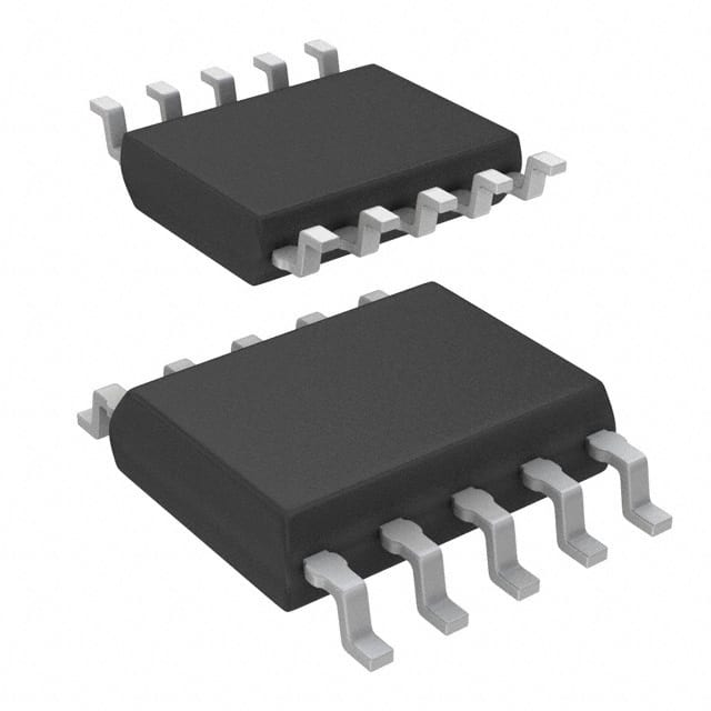
- Part No.:
- L4984DTR
- Manufacturer:
- STMicroelectronics
- Category:
- PFC (Power Factor Correction)
- Package:
- 10-SOP (0.154", 3.90mm Width)
- Datasheet:
-
 L4984DTR.pdf
- Description:
- IC PFC CTRLR CCM 10SSOP
- Quantity:
- Payment:

- Shipping:

Inventory:2,360
Please send an inquiry. Send us your inquiry, and we will respond immediately.
Product details
Overview
L4984DTR from STMicroelectronics is a current-mode CCM Power Factor Correction (PFC) controller using line-modulated fixed-off-time (LM-FOT) control, designed for boost-type pre-regulators in 1 kW+ switch-mode power supplies. It features a proprietary multiplier for THD minimization, bi-directional 1/V² voltage feedforward, 1% internal reference (at Tj = 25 °C), and a ±600/±800 mA totem-pole gate driver in SSOP10 package-enabling IEC61000-3-2-compliant desktop PC and server power supplies.
For engineers reviewing the L4984DTR datasheet, L4984DTR pinout, L4984DTR application, or L4984DTR equivalent, key selection criteria include LM-FOT modulation stability, THD optimizer circuit performance, OVP/FFD latch behavior, and compatibility with high-current MOSFETs or IGBTs in continuous conduction mode PFC stages.
Technical Context
The L4984DTR implements a proprietary line-modulated fixed-off-time modulator that maintains near-fixed switching frequency across AC line half-cycles while operating in CCM, unlike traditional critical-conduction-mode controllers. Its multiplier accepts MULT (pin 3) and VFF (pin 5) inputs to generate a sinusoidal current reference, with built-in 1/V² correction enabling robust line transient response during mains surges and brownouts.
Internal protection includes latched shutdown on feedback loop failure (detected via INV < 1.66 V concurrent with PFC_OK > 2.5 V), inductor saturation detection at 1.7 V on CS (pin 4), and digital leading-edge blanking (145–400 ns). The gate driver delivers 600 mA source / 800 mA sink with active pull-down during UVLO and 12 V output clamping.
Key Specifications
| Parameter | Value and Actual Design Meaning |
|---|---|
| VCC Operating Range | 10.3 V to 22.5 V - supports wide-input auxiliary supplies with internal 22.5 V Zener clamp. |
| Reference Voltage Accuracy | ±1% at Tj = 25 °C - ensures precise output voltage regulation in PFC stage feedback loop. |
| Gate Drive Current | −600 mA / +800 mA - drives large MOSFETs or IGBTs directly without external buffers. |
| CS Leading-Edge Blanking | 145–400 ns - suppresses noise-induced false turn-off during MOSFET switching transitions. |
| OVP Threshold | 2.435–2.565 V on PFC_OK - triggers latched shutdown if output overvoltage exceeds safe limit. |
| MULT Input Range | 0–3 V linear range - maps rectified AC line to accurate sinusoidal current reference for low THD. |
| UVLO Hysteresis | 2.3–2.7 V - prevents oscillation during marginal VCC conditions with clean startup/shutdown. |
Pinout & Package
SSOP10 package: 10-pin shrink small-outline package with 0.65 mm pitch, 4.4 mm × 3.0 mm body, and exposed thermal pad (per ST DocID024474 Rev 1, Figure 38).
| Pin/Terminal | Circuit Role | Design Meaning |
|---|---|---|
| 1 (INV) | Inverting input of error amplifier | Receives scaled PFC output voltage; <1.66 V with PFC_OK >2.5 V triggers latched FFD shutdown. |
| 2 (COMP) | Error amplifier output | Drives multiplier; clamped at 5.7–6.7 V high / 2.1–2.4 V low to enable burst-mode operation. |
| 3 (MULT) | Main multiplier input | Accepts rectified line via resistor divider; sets current reference amplitude and enables soft-start. |
| 4 (CS) | Current sense comparator input | Detects MOSFET current; 1.7 V threshold triggers saturation protection; 220 ns blanking improves noise immunity. |
| 5 (VFF) | Voltage feedforward (1/V²) input | Connects to RFF/CFF network; provides RMS line info and brownout detection (0.8 V shutdown). |
| 6 (PFC_OK) | OVP/Disable/Feedback failure monitor | 2.5 V OVP trip, 0.23 V disable, 1.66 V FFD trigger - dual-function safety and system coordination pin. |
| 7 (TIMER) | LM-FOT off-time programming | Charged by 142–163 µA current; CTIMER sets off-time (2.88–3.30 µs at VMULT=1 V). |
| 8 (GND) | Signal & gate driver return | Separate PCB trace required from sense resistor cold end to avoid ground bounce in high-di/dt paths. |
| 9 (GD) | Gate driver output | Totem-pole stage with 12 V clamp; drives gate directly; active pull-down during UVLO prevents shoot-through. |
| 10 (VCC) | Supply input | Internally clamped at 22.5 V min.; 10.3–22.5 V operating range; 65–150 µA startup current. |
Key Features
| Feature | Design Value |
|---|---|
| Line-modulated fixed-off-time (LM-FOT) control | Enables stable CCM operation with near-constant frequency across line cycle - reduces EMI filter complexity vs. variable-frequency alternatives. |
| Proprietary THD optimizer circuit | Combines 1/V² feedforward and multiplier linearity to achieve <10% THD across 20–100% load in 1 kW+ systems. |
| Bidirectional voltage feedforward | Responds to both line surges and sags within 300 µs - maintains regulation during JEIDA-MITI transient tests. |
| Latched feedback failure detection (FFD) | Shuts down permanently if INV < 1.66 V while PFC_OK > 2.5 V - prevents uncontrolled output rise due to open-loop failure. |
| Inductor saturation protection | Monitors CS pin for >1.7 V; halts switching and resets after safe delay - avoids core saturation damage in boost inductors. |
Applications
| Desktop PC Power Supply | Server SMPS |
|---|---|
Use Scenario: 80 PLUS Gold-certified ATX power supply with 750 W continuous output and active PFC stage. IC Role / Device Role / Timing Role: Primary CCM PFC controller regulating boost converter output at 385 V DC with LM-FOT timing synchronized to AC line zero-crossings. Use Value: Meets IEC61000-3-2 Class D harmonic limits up to full load while maintaining <5% efficiency penalty vs. no-PFC design. | Use Scenario: Dual-output 1200 W redundant server PSU compliant with ENERGY STAR® v8.0 and Blue Angel requirements. IC Role / Device Role / Timing Role: Front-end PFC controller managing input current shaping and output voltage hold-up; interfaces with downstream LLC controller via PFC_OK burst sync. Use Value: Enables >94% system efficiency at 50% load and passes JEIDA-MITI harmonic compliance for datacenter deployment. |
| Industrial Motor Drive | Medical Imaging Power System |
Use Scenario: 3-phase input rectifier + single-phase boost PFC stage feeding 400 V DC bus for variable-frequency drive inverter. IC Role / Device Role / Timing Role: Line-synchronized CCM PFC controller with brownout recovery (VFF > 0.88 V) and soft-restart after AC dropout. Use Value: Sustains regulated output during 20 ms AC dips per IEC61000-4-11, preventing inverter fault trips. | Use Scenario: High-reliability 1500 W X-ray generator power supply requiring ultra-low EMI and fail-safe OVP. IC Role / Device Role / Timing Role: Safety-critical PFC controller with latched OVP (PFC_OK > 2.5 V) and FFD shutdown to prevent capacitor overvoltage in diagnostic mode. Use Value: Guarantees <100 ms response to output overvoltage events, meeting IEC60601-1 clause 15.3.2 insulation coordination. |
Equivalent & Alternatives
The following parts are listed as comparable options for similar CCM PFC controller applications.
| Alternative Part | Technical Difference | Application Difference | Selection Advice |
|---|---|---|---|
| UCC28070DR | Two-phase interleaved CCM controller; requires external phase-control logic; no integrated THD optimizer. | Targeted at >2 kW systems needing ripple cancellation; lacks single-chip 1/V² feedforward. | Select when interleaving is mandatory and board space allows dual-channel layout. |
| FAN4803SMX | Fixed-frequency average-current-mode controller; no LM-FOT; lower gate drive (±500 mA); no latched FFD. | Suitable for cost-sensitive sub-500 W designs; requires external OVP and brownout circuits. | Choose only for non-compliant or legacy designs where THD <15% is acceptable. |
Compared with UCC28070DR and FAN4803SMX, the L4984DTR uniquely integrates LM-FOT modulation, THD optimization, and latched FFD in a single SSOP10 package-reducing BOM count and improving reliability in 1 kW+ IEC61000-3-2-compliant systems without requiring phase management or external protection ICs.
Availability
L4984DTR is available at Aetrix Electronics and suitable for desktop PC power supplies, server SMPS, industrial motor drives, and medical imaging power systems requiring stable component supply, long-term lifecycle support, and RoHS-compliant packaging.
Supply support for L4984DTR includes scheduled delivery planning, volume procurement assistance, BOM continuity management, traceable sourcing, and lifecycle availability coordination for OEM customers, industrial embedded developers, connected-device designers, and electronics production programs.
Manufacturer
STMicroelectronics is a global semiconductor leader headquartered in Geneva, Switzerland, designing and manufacturing analog, microcontroller, power, and sensor solutions for industrial, automotive, and consumer markets.
The L4984DTR belongs to ST's high-efficiency AC-DC power conversion product line, engineered specifically for cost-sensitive, high-power-factor, CCM-based PFC pre-regulators in computing and industrial power supplies.
FAQ
What is the purpose of the TIMER pin (pin 7) in the L4984DTR?
The TIMER pin programs the off-time of the external MOSFET via an external capacitor (CTIMER). An internal 142–163 µA current charges CTIMER during MOSFET off-time; when its voltage matches the MULT pin voltage, the off-time ends and the gate driver turns on. This LM-FOT mechanism ensures stable CCM operation with near-constant frequency across the AC line cycle.
How does the L4984DTR implement brownout protection?
Brownout protection is implemented on the VFF pin (pin 5): when voltage drops below 0.8 V, the IC shuts down non-latched and enters low-consumption state; restart occurs automatically when VFF rises above 0.88 V. This function uses the same internal comparator that supports 1/V² feedforward, ensuring coordinated response to line undervoltage without external components.
Can the L4984DTR be used in discontinuous conduction mode (DCM)?
No-the L4984DTR is explicitly designed for continuous conduction mode (CCM) PFC operation only. Its LM-FOT modulator, multiplier architecture, and protection thresholds (e.g., 1.7 V CS saturation detection) assume CCM waveforms. Attempting DCM operation results in unstable current shaping, excessive THD, and potential false saturation triggers due to inherent current zero-crossing behavior.
What happens during feedback loop failure (FFD) and how is it cleared?
FFD occurs when INV voltage falls below 1.66 V *while* PFC_OK voltage exceeds 2.5 V-indicating open-loop regulator failure. The device enters latched shutdown: GD stops switching, COMP is clamped low, and VCC must be cycled to reset. This prevents uncontrolled output voltage rise and capacitor overvoltage, meeting safety requirements for Class II isolated supplies.
L4984DTR Specifications
- Product attributes
- Attribute value
- Manufacturer:
- STMicroelectronics
- Series:
- -
- Package/Case:
- 10-SOP (0.154", 3.90mm Width)
- Packaging:
- Tape & Reel (TR)
- Product Status:
- Active
- Mode:
- Continuous Conduction (CCM)
- Frequency - Switching:
- -
- Current - Startup:
- 65 µA
- Voltage - Supply:
- 10.3V ~ 22.5V
- Operating Temperature:
- -40°C ~ 150°C
- Grade:
- -
- Qualification:
- -
- Mounting Type:
- Surface Mount
- Supplier Device Package:
- 10-SSOP
L4984DTR FAQ
1.How can I place an order for L4984DTR through Aetrix?
Please submit a Request for Quotation (RFQ) for L4984DTR on Aetrix. Our sales agent will provide a competitive quotation and guide you through the order confirmation once you accept the terms.
2.Are the price and stock information for L4984DTR reliable?
The price and inventory of L4984DTR are updated periodically and may fluctuate due to market conditions. Stock and pricing data are typically refreshed every 24 hours. Quotation validity for L4984DTR is usually 5 days.
3.What payment methods are accepted for L4984DTR?
We accept Wire Transfer, PayPal, Credit Card, Western Union, MoneyGram, and Escrow for L4984DTR transactions.
Note: Certain payment methods may incur a processing fee.
4.How is shipping managed for L4984DTR?
L4984DTR orders can be shipped via leading logistics carriers, including DHL, UPS, FedEx, TNT, or Registered Mail.
Once your L4984DTR order is processed, you will receive an email with the shipment details and tracking number.
Note: Tracking information may take up to 24 hours to appear. Express delivery typically takes 3–5 business days.
5.How can I obtain technical support or documentation for L4984DTR?
For technical support, including L4984DTR datasheets, pinout diagrams, or application guidance, please contact our engineering support team. They can provide detailed documentation and assistance for your L4984DTR requirements.
6.How does Aetrix verify that L4984DTR is sourced from the original manufacturer or authorized distributors?
All L4984DTR products on Aetrix are procured from qualified distributors and authorized channels. Our dedicated quality assurance team conducts strict verification, including traceability checks and, if necessary, third-party testing. This ensures that L4984DTR meets industry standards.
7.What is the process for return or replacement of L4984DTR?
All L4984DTR units undergo pre-shipment inspection (PSI). If there is an issue with L4984DTR, returns or replacements are accepted under the following conditions:
1.Quantity discrepancies, incorrect items, or visible external defects (such as breakage or corrosion), acknowledged by Aetrix.
2.The issue is reported within 90 days of delivery.
3.The L4984DTR part is unused and in its original packaging.
Return procedure for L4984DTR:
1.Submit a request within 90 days.
2.Obtain a Return Material Authorization (RMA) from Aetrix.
L4984DTR Tags

-
ICE2PCS01GXUMA1
Infineon Technologies

-
NCP1654BD133R2G
onsemi
-
MC33262DR2G
onsemi
-
ICE3PCS03GXUMA1
Infineon Technologies
-
NCP1631DR2G
onsemi

-
L4981BD013TR
STMicroelectronics
-
UCC28070DWR
Texas Instruments

-
UCC28070PWR
Texas Instruments

-
UC3854DWTR
Texas Instruments
-
L4981AD013TR
STMicroelectronics

-
UCC2817D
Texas Instruments
-
UC2854BDWTR
Texas Instruments
Tech Hub

Jumper cables guide covering safe connection order, red and black clamp placement, final ground connection, cable gauge, length, clamp quality, copper vs CCA cables, jump starter comparison and battery…

LDO regulator guide covering low dropout voltage, power dissipation, thermal design, PSRR, output noise, capacitor stability, adjustable LDO circuits, LDO vs buck converter and datasheet selection chec…

Conditional Access Module guide covering CAM meaning, CI/CI+ interface, smart card authorization, DVB security workflow, TV and set-top box compatibility, internal electronics, ESD protection, connecto…

Guide to electronic component obsolescence covering EOL risk, PCN/PDN notices, last-time buy planning, replacement options, form-fit-function validation, counterfeit risk and BOM lifecycle management.

18650 battery guide covering lithium-ion cell basics, 3.6V/3.7V voltage, 4.2V charging, mAh and Wh capacity, protected cells, chargers, BMS, series-parallel packs, holders, welding and sourcing checks.…

Hall effect sensor guide covering working principle, linear and digital sensors, Arduino circuits, current sensing, speed detection, automotive applications, A3144 examples, signal filtering and datash…

Product Change Notification guide for electronic components, covering PCN meaning, PCN vs PDN/EOL, common change types, risk levels, form-fit-function review, engineering validation, BOM control, LTB/L…

A practical guide to blend door actuators, covering HVAC function, symptoms, location, AC and heater issues, reset and calibration, replacement cost, electrical diagnosis, compatibility checks, and rep…

Engineering guide to Raspberry Pi alternatives, covering chip-level differences, Orange Pi, ROCK, Jetson, Banana Pi, NanoPi, Compute Module, Pico, GPIO, camera, HAT compatibility, and replacement risks…

Engineering guide to dynamic load response testing for high-current buck converters, covering load step setup, slew rate, Vcore undershoot, overshoot, recovery time, probe location, output capacitors a…


