
 My Inquiry
 My Account


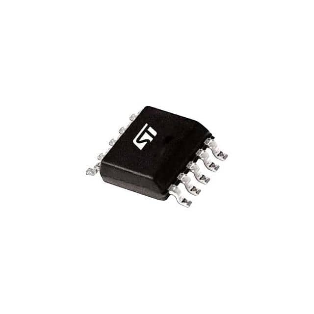
STMicroelectronics L4986B
- Part No.:
- L4986B
- Manufacturer:
- STMicroelectronics
- Category:
- PFC (Power Factor Correction)
- Package:
- 10-SOP (0.154", 3.90mm Width)
- Datasheet:
-
 L4986B.pdf
- Description:
- CCM PFC CONTROLLER WITH HIGH VOL
- Quantity:
- Payment:

- Shipping:

Inventory:410
Please send an inquiry. Send us your inquiry, and we will respond immediately.
Product details
Overview
L4986B from STMicroelectronics is a peak current-mode CCM-operated PFC controller for boost converters, featuring 130 kHz switching frequency, 800 V high-voltage startup with integrated AC sensing, and proprietary multiplier "emulator" enabling <1% THD across CCM/DCM modes. It integrates active X-capacitor discharge, brown-in/brownout protection compliant with IEC 60601-1-2, and totem-pole gate driver (0.7 A source / 1.5 A sink) for MOSFET/IGBT drive in >1 kW medical and industrial SMPS.
For engineers reviewing the L4986B datasheet, L4986B pinout, L4986B application, or L4986B equivalent, this controller delivers verified quasi-fixed-frequency operation, line-synchronized current shaping without external multiplier ICs, PGOOD_IN/PGOOD_OUT monitoring for output regulation integrity, and ultra-low standby consumption via HV-driven X-cap discharge - critical for IEC 62368-1 and Energy Star-compliant designs.
Technical Context
The L4986B implements fixed-off-time (FOT) control with a proprietary off-time modulator that maintains quasi-constant 130 kHz switching across input voltage (94–117 VPK) and load conditions. Its "multiplier emulator" replaces analog multipliers by combining FB error voltage, HV-sensed line voltage, and zero-current detection to synthesize a sinusoidal current reference without external components.
It features dual overcurrent protection: first-level OCP at −490 mV (peak inductor current limit) and second-level saturation detection at −750 mV, coupled with 150 ns leading-edge blanking and 10 µs disconnection debounce. The 2.5 V ±1.2% internal reference (Tj = 25 °C) feeds a transconductance OTA with 200 µS gain and 5 MΩ output impedance, stabilized via COMP-to-GND compensation network.
Key Specifications
| Parameter | Value and Actual Design Meaning |
|---|---|
| Switching frequency | 130 kHz typical - enables smaller EMI filter and boost inductor vs. 65 kHz L4986A, reducing system size in high-power LED and server SMPS. |
| High-voltage startup | 800 V rated HV pin - eliminates external startup resistor and enables direct AC-line sensing for brownout detection and feedforward. |
| THD performance | <1% THD in all CCM/DCM conditions - achieved via KCCM = 0.55 THD-CCM optimizer and KM = 0.10 V/V equivalent multiplier gain above 235 VPK. |
| Gate driver capability | 0.7 A source / 1.5 A sink - directly drives high-Qg MOSFETs or IGBTs without external buffer, supporting >1 kW PFC stages. |
| Brownout protection | 100 VPK threshold with 630 ms debounce - ensures regulated output during 500 ms mains dips per IEC 60601-1-2 for medical equipment. |
| Reference voltage | 2.50 V ±1.2% at Tj = 25 °C - provides stable feedback setpoint for precise VBULK regulation across temperature and line variations. |
| X-cap discharge | Active HV-pin sink current >5 mA - discharges EMI X-caps to <45 V within 77 ms, removing need for power-wasting bleed resistors. |
Pinout & Package
SSOP10 package (3.9 mm × 4.9 mm, 0.65 mm pitch), thermally optimized for surface-mount assembly in high-density PFC boards. Pin 9 is NC (high-voltage spacer) to ensure creepage compliance on PCB.
| Pin/Terminal | Circuit Role | Design Meaning |
|---|---|---|
| VCC | IC supply rail | Internally charged via HV pin; clamped at 24.5 V; requires local 100 nF bypass for clean bias under 2.8 mA operating current. |
| GD | Power switch gate driver | Totem-pole output driving MOSFET/IGBT gates; 0.7 A source / 1.5 A sink ensures fast turn-on/turn-off of high-Ciss devices. |
| GND | Signal + power return | Single-point ground tie for bias circuitry and gate driver return; must be isolated from noisy power return paths. |
| CS | Inductor current sense input | Accepts negative voltage from Rsense; triggers −490 mV OCP and −750 mV saturation protection; supports THD-CCM optimization via RTHD_CCM. |
| PG_OUT | Open-drain power-good indicator | Pulled low when FB > 2.375 V and PG_IN > 1.25 V; signals valid bulk voltage to downstream DC-DC controllers. |
| PG_IN | Adjustable PGOOD threshold input | Connected to VBULK divider; sets turn-off threshold for PG_OUT; internal clamp limits to 3.0 V max. |
| FB | Inverting OTA input | Receives scaled VBULK; internal 2.5 V reference enables precise regulation; 7% D_OVP disables switching if VFB exceeds 2.675 V. |
| COMP | OTA output / loop compensation | Drives external RC network for stability; drops below 1.0 V to enter burst mode; pulled below 0.7 V to disable IC entirely. |
| N.C. | High-voltage isolation spacer | No internal connection; physically separates HV and LV sections to meet creepage requirements per IEC 62368-1. |
| HV | AC line sensing & startup generator | Withstands 800 V; senses rectified AC for feedforward, brownout, and X-cap discharge; sinks >5 mA when AC removed. |
Key Features
| Feature | Design Value |
|---|---|
| Proprietary multiplier emulator | Replaces analog multiplier ICs; synthesizes sinusoidal current reference using HV pin voltage, FB error, and ZCD - reduces BOM count by ≥3 components. |
| Active X-capacitor discharge | HV pin sinks ≥5 mA to discharge EMI X-caps to <45 V within 77 ms - eliminates 1–2 W standby loss from traditional bleed resistors. |
| Dual-level overcurrent protection | −490 mV (normal OCP) and −750 mV (saturation detection) with 150 ns blanking - prevents false triggering while ensuring robust inductor fault response. |
| Medical-grade brownout immunity | 100 VPK detection with 630 ms debounce and restart hysteresis - guarantees continuous regulation during 500 ms dips per IEC 60601-1-2 Clause 8.8.2. |
| Quasi-fixed 130 kHz operation | FSW varies <±5% across line/load - simplifies EMI filter design vs. variable-frequency controllers and avoids audible noise in LED drivers. |
Applications
| Server Power Supply | Medical Imaging PSU |
|---|---|
|
Use Scenario: 1.5 kW redundant ATX-style power supply for rack-mounted servers requiring EN61000-3-2 Class A compliance and <5% THD. IC Role / Device Role / Timing Role: Primary PFC controller in boost pre-regulator stage; regulates 380–400 V DC bus; synchronizes current waveform to 50/60 Hz AC line via HV pin sensing. Use Value: 130 kHz operation allows 40% smaller boost inductor vs. 65 kHz alternatives; active X-cap discharge meets ENERGY STAR® Tier 2 standby loss limits (<0.5 W). |
Use Scenario: 2 kW isolated DC-DC front-end for MRI gradient amplifier, requiring IEC 60601-1-2 immunity to 500 ms mains interruptions. IC Role / Device Role / Timing Role: CCM PFC controller enforcing regulated 400 V output despite 100–117 VPK brownouts; PG_OUT signals downstream DC-DC enable only when VBULK is stable. Use Value: Brown-in/brownout thresholds (110 VPK/100 VPK) and 630 ms debounce ensure uninterrupted operation during hospital grid sags; soft-start prevents inrush into large hold-up capacitors. |
| High-Bay LED Driver | Industrial Motor Drive Front-End |
|
Use Scenario: 300 W constant-current LED driver for warehouse lighting, operating from universal 90–264 VAC input with JEIDA-MITI compliance. IC Role / Device Role / Timing Role: Single-stage PFC controller managing boost converter; uses THD-CCM optimizer to maintain <7% THD at 10% load via RTHD_CCM tuning. Use Value: SSOP10 footprint and minimal external parts (no multiplier, no startup resistor) reduce PCB area by 35% vs. legacy PFC ICs; 0.8 mA quiescent current enables DALI dimming compatibility. |
Use Scenario: 5 kW VFD front-end with regenerative braking, requiring robust PFC under unbalanced 3-phase rectified input and harmonic-rich loads. IC Role / Device Role / Timing Role: Boost PFC controller handling 500 VDC bus; CS pin monitors inductor current with 150 ns blanking to reject switching noise from IGBT bridge. Use Value: Dual OCP levels prevent false trips during motor startup surges; HV pin withstands 600 V transient per IEC 61800-5-1; 150 °C junction rating supports convection-cooled enclosures. |
Equivalent & Alternatives
The following parts are listed as comparable options for similar CCM PFC controller applications.
| Alternative Part | Technical Difference | Application Difference | Selection Advice |
|---|---|---|---|
| ICE3PCS01G | Fixed 65 kHz frequency; no HV startup (requires external bias); no X-cap discharge; uses traditional analog multiplier. | Lacks medical brownout timing compliance and active safety discharge - unsuitable for IEC 60601-1-2 or ENERGY STAR® systems. | Select only for cost-sensitive, non-medical 1 kW designs where external startup and bleed resistors are acceptable. |
| UCC28070 | Two-phase interleaved CCM controller; 115–275 kHz programmable frequency; no integrated HV startup; requires external OVP/OTP. | Targets higher-power (>2 kW) systems needing phase interleaving; lacks single-chip X-cap discharge and medical brownout logic. | Prefer for >2 kW telecom rectifiers where ripple cancellation outweighs BOM simplicity; not drop-in for L4986B's SSOP10 layout. |
Compared with ICE3PCS01G and UCC28070, the L4986B uniquely integrates 800 V HV startup, active X-cap discharge, and IEC 60601-1-2–compliant brownout timing in a single SSOP10 package - eliminating 4–6 external components and enabling certified medical/industrial PFC designs with minimal layout effort.
Availability
L4986B is available at Aetrix Electronics and suitable for server power supplies, medical imaging PSUs, high-bay LED drivers, and industrial motor drive front-ends requiring stable component supply, long-term lifecycle support, and traceable sourcing for safety-critical applications.
Supply support for L4986B includes scheduled delivery planning, volume procurement assistance, BOM continuity management, traceable sourcing, and lifecycle availability coordination for OEM customers, industrial embedded developers, connected-device designers, and electronics production programs.
Manufacturer
STMicroelectronics is a global semiconductor leader headquartered in Geneva, designing and manufacturing analog, microcontroller, power, and sensor solutions for automotive, industrial, and consumer markets.
The L4986B belongs to ST's high-voltage analog power IC portfolio, engineered specifically for energy-efficient, safety-certified PFC pre-regulators in medical, server, and industrial power supplies - emphasizing integration, reliability, and regulatory compliance.
FAQ
What is the purpose of the NC pin (Pin 9) on the L4986B?
Pin 9 is a no-connect (NC) terminal used solely as a high-voltage spacer to increase creepage distance between the HV and LV sections of the IC. It is not internally bonded and must remain unconnected on the PCB to ensure compliance with IEC 62368-1 insulation requirements. Routing traces or placing vias near this pin is prohibited.
How does the L4986B achieve THD <1% without an external multiplier IC?
The L4986B uses a proprietary "multiplier emulator" that combines the FB error voltage, HV pin AC-sensing signal, and zero-current detection (ZCD) to synthesize a line-synchronized current reference. This eliminates the need for external analog multipliers while maintaining <1% THD across CCM and DCM modes via KCCM = 0.55 THD-CCM optimization and adaptive gain scaling.
Can the L4986B replace the L4986A in an existing design?
Yes, but only with layout and compensation adjustments: L4986B runs at 130 kHz (vs. 65 kHz), requiring halved boost inductor value and revised COMP compensation network for loop stability. The HV, CS, and PG pins are functionally identical; however, minimum off-time (0.5 µs) and maximum on-time (20 µs) differ - verify timing margins under worst-case line/load.
What happens during an inductor saturation event detected at the CS pin?
When CS voltage falls to −750 mV (VCS_OCP2), the L4986B immediately halts switching and enters latch-off state until CS rises above −10 mV (VCS_ZCD). This prevents destructive current runaway during saturation, core faults, or shorted windings. Recovery requires full reset of VCC UVLO or external COMP pull-down to re-enable.
L4986B Specifications
- Product attributes
- Attribute value
- Manufacturer:
- STMicroelectronics
- Series:
- -
- Package/Case:
- 10-SOP (0.154", 3.90mm Width)
- Packaging:
- Tube
- Product Status:
- Active
- Mode:
- Continuous Conduction (CCM)
- Frequency - Switching:
- 130kHz
- Current - Startup:
- 400 µA
- Voltage - Supply:
- 10V ~ 24.5V
- Operating Temperature:
- -40°C ~ 150°C (TJ)
- Grade:
- -
- Qualification:
- -
- Mounting Type:
- Surface Mount
- Supplier Device Package:
- 10-SSOP
L4986B FAQ
1.How can I place an order for L4986B through Aetrix?
Please submit a Request for Quotation (RFQ) for L4986B on Aetrix. Our sales agent will provide a competitive quotation and guide you through the order confirmation once you accept the terms.
2.Are the price and stock information for L4986B reliable?
The price and inventory of L4986B are updated periodically and may fluctuate due to market conditions. Stock and pricing data are typically refreshed every 24 hours. Quotation validity for L4986B is usually 5 days.
3.What payment methods are accepted for L4986B?
We accept Wire Transfer, PayPal, Credit Card, Western Union, MoneyGram, and Escrow for L4986B transactions.
Note: Certain payment methods may incur a processing fee.
4.How is shipping managed for L4986B?
L4986B orders can be shipped via leading logistics carriers, including DHL, UPS, FedEx, TNT, or Registered Mail.
Once your L4986B order is processed, you will receive an email with the shipment details and tracking number.
Note: Tracking information may take up to 24 hours to appear. Express delivery typically takes 3–5 business days.
5.How can I obtain technical support or documentation for L4986B?
For technical support, including L4986B datasheets, pinout diagrams, or application guidance, please contact our engineering support team. They can provide detailed documentation and assistance for your L4986B requirements.
6.How does Aetrix verify that L4986B is sourced from the original manufacturer or authorized distributors?
All L4986B products on Aetrix are procured from qualified distributors and authorized channels. Our dedicated quality assurance team conducts strict verification, including traceability checks and, if necessary, third-party testing. This ensures that L4986B meets industry standards.
7.What is the process for return or replacement of L4986B?
All L4986B units undergo pre-shipment inspection (PSI). If there is an issue with L4986B, returns or replacements are accepted under the following conditions:
1.Quantity discrepancies, incorrect items, or visible external defects (such as breakage or corrosion), acknowledged by Aetrix.
2.The issue is reported within 90 days of delivery.
3.The L4986B part is unused and in its original packaging.
Return procedure for L4986B:
1.Submit a request within 90 days.
2.Obtain a Return Material Authorization (RMA) from Aetrix.
L4986B Tags

-
ICE2PCS01GXUMA1
Infineon Technologies

-
NCP1654BD133R2G
onsemi
-
MC33262DR2G
onsemi
-
ICE3PCS03GXUMA1
Infineon Technologies
-
NCP1631DR2G
onsemi

-
L4981BD013TR
STMicroelectronics
-
UCC28070DWR
Texas Instruments

-
UCC28070PWR
Texas Instruments

-
UC3854DWTR
Texas Instruments
-
L4981AD013TR
STMicroelectronics

-
UCC2817D
Texas Instruments
-
UC2854BDWTR
Texas Instruments
Tech Hub

A practical engineering and sourcing framework covering lifecycle verification, lifetime-buy calculations, replacement qualification, supplier checks and counterfeit-risk controls.

TTL and CMOS logic families differ in thresholds, loading, output drive, power and timing. This engineering guide compares 74HC and 74HCT, calculates noise margins and checks 3.3 V/5 V compatibility.

A practical engineering guide to 3.3V and 5V logic compatibility, input thresholds, resistor dividers, translator ICs, MOSFET level shifting, I2C pull-ups, timing limits and power-sequencing risks.

The 74HC595 uses push-pull logic outputs, while the TPIC6B595 uses 50 V open-drain DMOS sinks for higher-power loads. This guide compares timing, current limits, 3.3 V interfacing, load wiring, thermal…

The 74HC595 converts serial data into eight stable parallel outputs. This guide covers pin functions, shift and storage timing, OE and MR behavior, drive-current limits, cascading, voltage compatibilit…

A technical comparison of level-sensitive latches and edge-triggered flip-flops, covering timing windows, setup and hold limits, master–slave operation, time borrowing, race-through, HDL inference and…

A D latch stores one bit while Enable controls when data can pass. This reference covers gate-level operation, truth tables, transparency, setup and hold timing, LE versus OE, common ICs and practical …

An SR latch stores one bit through cross-coupled feedback. This engineering reference covers NOR and NAND implementations, truth tables, forbidden-state recovery, gated operation, switch debouncing, fa…

Latch circuits retain one bit through feedback. This technical reference covers SR and D latches, truth tables, transparency, timing limits, latch-versus-flip-flop behavior, applications and common log…

An engineering guide to LED driver operation, constant-current and constant-voltage outputs, linear and switching topologies, dimming, IC selection, calculations, replacement compatibility, and fault c…


