
 My Inquiry
 My Account


STMicroelectronics L5951
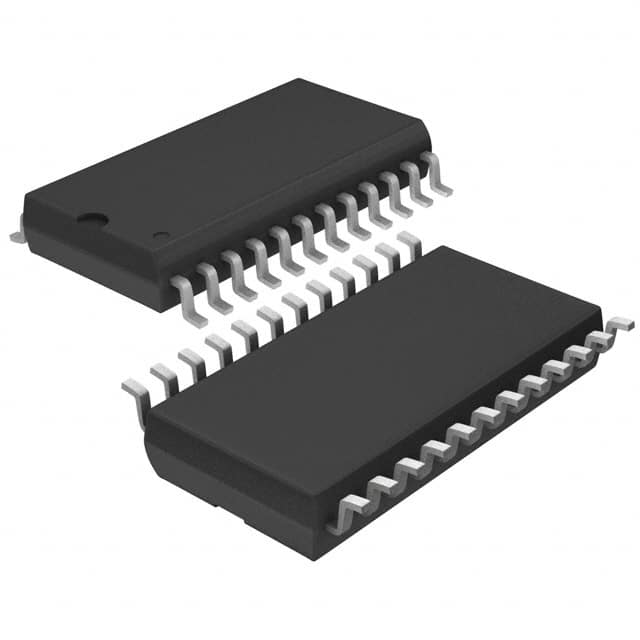
- Part No.:
- L5951
- Manufacturer:
- STMicroelectronics
- Category:
- Special Purpose Regulators
- Package:
- 24-SOIC (0.295", 7.50mm Width)
- Datasheet:
-
 L5951.pdf
- Description:
- IC REG CONV CAR AUDIO 3OUT 24SO
- Quantity:
- Payment:

- Shipping:

Inventory:3,497
Please send an inquiry. Send us your inquiry, and we will respond immediately.
Product details
Overview
L5951 from STMicroelectronics is a monolithic triple-output voltage regulator IC with integrated SAE J1850 Class 2/IDR transceiver, designed for automotive car radio power and communication subsystems. It delivers regulated 3.3 V (100 mA), 5 V (100 mA), and 7.8 V (100 mA) outputs, features out-of-regulation detection on the 5 V rail, supports wide input range (4.5–26.5 V), and includes controlled output slope for low EMI in vehicle bus environments.
For engineers reviewing the L5951 datasheet, L5951 pinout, L5951 application, or L5951 equivalent, this device serves as a system-level power + interface solution for microcontroller-based automotive infotainment modules requiring simultaneous regulated supplies and single-wire J1850 physical layer compliance.
Technical Context
The L5951 integrates three independent linear regulators-REG1 (3.3 V, non-LDO), REG2 (5 V, LDO), and REG3 (7.8 V, LDO, enable-controlled)-with dedicated ground paths (GND_REG, GND_TX) and thermal shutdown thresholds differentiated by function (160°C for REG1/REG2, 150°C for REG3/BUS driver). Each regulator includes current limiting (280 mA typ.) and load regulation <100 mV across full current range.
Its J1850 transceiver implements VPW protocol with programmable waveshaping via external REXT, 4X mode support (41.6 kBaud), loopback capability, and BUS timing compliance (trise/tfall ≤15 µs, tdelay = 16 µs). The IC survives 34 V load dump, ±2 V ground offset, and loss-of-ground conditions while maintaining RX functionality in sleep mode.
Key Specifications
| Parameter | Value and Actual Design Meaning |
|---|---|
| Output voltages | 3.3 V (REG1), 5 V (REG2), 7.8 V (REG3); all rated for 100 mA continuous, 280 mA short-circuit limit |
| Input voltage range | 4.5–26.5 V DC operating; withstands 34 V transient (50 ms), enabling direct battery connection in 12 V automotive systems |
| Standby quiescent current | <150 µA (typ. 110 µA) with EN/Sleep* = 0 V, critical for always-on radio standby modes |
| Regulator dropout | REG2: 22 mV @ 5 mA; REG3: 40 mV @ 5 mA - enables stable operation down to ~7.0 V battery input |
| J1850 BUS timing | trise/tfall ≤15 µs, propagation delay = 16 µs, spectral emission <100 µV (0.53–1 MHz) - meets SAE J1850 EMI requirements |
| Protection features | Overtemperature shutdown (150–160°C), loss-of-ground survival, 4000 V HBM ESD, no reverse-battery tolerance (external protection required) |
| Reset threshold | Active-low Reset pin asserts at VREG2 ≤4.70 V (hysteresis = 50 mV), providing deterministic MCU reset during brownout |
Pinout & Package
Package: SO-24 (Small Outline, 24-pin, 0.600" body width, 1.27 mm pitch).
| Pin/Terminal | Circuit Role | Design Meaning |
|---|---|---|
| 1 (REG1) | 3.3 V regulator output | Supplies low-power MCU peripherals; non-LDO architecture requires ≥1.2 V headroom above 3.3 V |
| 2 (RESET) | Active-low reset output | Asserts when REG2 drops below 4.70 V; 50 mV hysteresis prevents chatter during slow voltage recovery |
| 3 (REXT) | Waveshaping resistor connection | External resistor sets rise/fall time of BUS signal; disables waveshaping when 4X = high |
| 4,6–8,17,18,19,20 (GND_REG) | Regulator ground reference | Dedicated ground path isolates regulator noise from transceiver circuitry |
| 5,9,10,12,13,14,15,16 (GND_TX) | Transceiver ground reference | Separate ground plane minimizes coupling between digital TX/RX and analog regulator sections |
| 11 (4X) | 4X baud rate mode control | Logic low enables 4× speed (41.6 kBaud); logic high uses standard 10.4 kBaud VPW timing |
| 21 (BAT) | Main battery supply input | Accepts 4.5–26.5 V; internal protection handles 34 V transients without external clamp |
| 22 (REG3) | 7.8 V regulator output | Enable-controlled (pin 10); powers high-voltage audio stages or analog front-ends in radio designs |
| 23 (REG2) | 5 V regulator output | LDO architecture ensures stable MCU core supply across full battery range; drives Reset circuit |
| 24 (LVS) | Low-voltage supply input | Alternative input to reduce power dissipation when VBAT >12 V; bypasses linear regulator headroom loss |
Key Features
| Feature | Design Value |
|---|---|
| Triple independent regulators | 3.3 V/5 V/7.8 V outputs with separate grounds and thermal shutdown thresholds optimize noise isolation and fault containment |
| Integrated J1850 Class 2/IDR | Single-chip replacement for discrete transceiver + regulator combos; eliminates external waveshaping components and timing calibration |
| Programmable BUS slope control | REXT-based rise/fall time tuning reduces conducted EMI without sacrificing VPW timing compliance |
| Loss-of-ground survivability | Continues receiving BUS messages and asserting RX even when assembly ground is disconnected - critical for field reliability |
| Low-quiescent-current sleep mode | <150 µA total ICC in Sleep* = low state, enabling multi-week battery drain tolerance in parked vehicle scenarios |
Applications
| Automotive Infotainment Head Unit | Body Control Module (BCM) Gateway |
|---|---|
|
Use Scenario: Central radio unit requiring isolated 3.3 V (MCU core), 5 V (peripherals), and 7.8 V (audio amplifier bias) supplies plus J1850 diagnostics interface. IC Role / Device Role / Timing Role: Single-chip power management + physical layer transceiver; provides synchronized regulator startup and BUS-ready signaling via RESET assertion. Use Value: Reduces BOM count by 7+ discrete regulators and transceiver ICs; eliminates external waveshaping RC networks and reset supervisor ICs. |
Use Scenario: Gateway node translating between CAN and J1850 networks, needing regulated supplies for dual-MCU architecture and robust bus communication under load-dump stress. IC Role / Device Role / Timing Role: Dual-role regulator/transceiver - REG2 powers primary MCU, REG3 powers secondary CAN transceiver, BUS handles legacy J1850 diagnostics polling. Use Value: Survives 34 V load dump without latch-up; maintains RX reception during loss-of-ground events, ensuring diagnostic continuity during chassis faults. |
| Aftermarket Car Stereo | Industrial Vehicle Telematics |
|
Use Scenario: Compact aftermarket stereo with space-constrained PCB layout, requiring minimal external components for power and J1850 connectivity to OEM dash displays. IC Role / Device Role / Timing Role: System power hub - REG1 powers display controller, REG2 powers main SoC, BUS communicates with factory HVAC/climate module via J1850. Use Value: SO-24 footprint consolidates 3 regulators + transceiver into one package; 4X mode enables faster firmware updates over J1850 without changing bus infrastructure. |
Use Scenario: Ruggedized telematics unit mounted in construction equipment, exposed to wide temperature (-40°C to +85°C) and ground-offset conditions. IC Role / Device Role / Timing Role: Power + interface conditioner - LVS input reduces thermal stress at 24 V nominal; GND_TX/GND_REG separation prevents sensor noise coupling into GPS/IMU supplies. Use Value: Operates down to 4.9 V battery input while sustaining BUS receive capability; ±2 V ground offset tolerance eliminates need for isolated bus couplers. |
Equivalent & Alternatives
The following parts are listed as comparable options for similar automotive triple-regulator + J1850 interface applications.
| Alternative Part | Technical Difference | Application Difference | Selection Advice |
|---|---|---|---|
| MC33883 | Standalone J1850 transceiver only; no integrated regulators - requires external 3.3/5/7.8 V supplies | Used where existing power architecture exists; lacks L5951's power consolidation and low-IQ sleep mode | Select when upgrading legacy designs with proven regulator layout; not suitable for new compact radio designs. |
| TLE6220 | Triple LDO regulator (5/3.3/2.5 V) with LIN interface - no J1850 support, different protocol stack and timing | Targets LIN-based body electronics; incompatible with SAE J1850 VPW framing and BUS voltage levels (0–7.7 V) | Choose only for LIN-based systems; cannot replace L5951 in J1850 diagnostic or radio communication roles. |
Compared with MC33883 and TLE6220, the L5951 uniquely combines triple-voltage regulation, J1850 physical layer, and ultra-low standby current in one SO-24 package - eliminating inter-IC routing, reducing thermal footprint, and enabling true single-chip car radio power + interface solutions.
Availability
L5951 is available at Aetrix Electronics and suitable for automotive infotainment systems, body control modules, and industrial telematics requiring stable component supply across extended temperature and voltage ranges.
Supply support for L5951 includes scheduled delivery planning, volume procurement assistance, BOM continuity management, traceable sourcing, and lifecycle availability coordination for OEM customers, industrial embedded developers, connected-device designers, and electronics production programs.
Manufacturer
STMicroelectronics is a global semiconductor leader specializing in automotive-grade analog, power, and microcontroller solutions with ISO/TS 16949 certified manufacturing.
The L5951 belongs to ST's Automotive Power Management portfolio, engineered specifically for car radio and infotainment subsystems needing integrated power regulation and legacy J1850 diagnostics interface in a single monolithic IC.
FAQ
What is the minimum battery voltage at which the L5951 maintains BUS receive functionality?
The L5951 sustains RX operation down to 4.9 V battery input, allowing diagnostic message reception even during deep brownout conditions. Below 7.0 V, regulator outputs remain active but BUS VOH is not guaranteed below VBAT = 9.0 V; RX continues functioning due to internal level-shifting circuitry independent of REG3 status.
How does the LVS pin improve thermal performance in high-input-voltage automotive applications?
The LVS (Low Voltage Supply) pin provides an auxiliary input that bypasses the linear regulator headroom loss for REG1 and REG2. When VLVS ≈ 7–10 V is supplied, power dissipation drops significantly versus using VBAT directly - reducing junction temperature by up to 25°C at 24 V input, delaying thermal shutdown onset.
Can the L5951 drive more than 32 nodes on a J1850 bus?
No - the L5951 is specified to drive up to 32 remote transceivers per SAE J1850 specification. Exceeding this count violates RC time constant requirements (target ~5 ms), causing VPW pulse distortion and CRC errors. With >26 nodes, all nodes must use 470 pF + 10.6 kΩ termination to maintain bus impedance.
Is reverse-battery protection integrated into the L5951?
No - the L5951 lacks internal reverse-polarity protection and will be damaged if VBAT is connected with negative polarity. External protection (e.g., series MOSFET with gate-driven charge pump or ideal diode controller) must be implemented upstream of the BAT pin to ensure survivability in service environments where battery terminals may be misconnected.
L5951 Specifications
- Product attributes
- Attribute value
- Manufacturer:
- STMicroelectronics
- Series:
- -
- Package/Case:
- 24-SOIC (0.295", 7.50mm Width)
- Packaging:
- Tube
- Product Status:
- Active
- Applications:
- Converter, Car Audio System
- Voltage - Input:
- 4.5V ~ 26.5V
- Number of Outputs:
- 3
- Voltage - Output:
- 3.3V, 5V, 7.8V
- Operating Temperature:
- -40°C ~ 85°C
- Grade:
- -
- Qualification:
- -
- Mounting Type:
- Surface Mount
- Supplier Device Package:
- 24-SO
L5951 FAQ
1.How can I place an order for L5951 through Aetrix?
Please submit a Request for Quotation (RFQ) for L5951 on Aetrix. Our sales agent will provide a competitive quotation and guide you through the order confirmation once you accept the terms.
2.Are the price and stock information for L5951 reliable?
The price and inventory of L5951 are updated periodically and may fluctuate due to market conditions. Stock and pricing data are typically refreshed every 24 hours. Quotation validity for L5951 is usually 5 days.
3.What payment methods are accepted for L5951?
We accept Wire Transfer, PayPal, Credit Card, Western Union, MoneyGram, and Escrow for L5951 transactions.
Note: Certain payment methods may incur a processing fee.
4.How is shipping managed for L5951?
L5951 orders can be shipped via leading logistics carriers, including DHL, UPS, FedEx, TNT, or Registered Mail.
Once your L5951 order is processed, you will receive an email with the shipment details and tracking number.
Note: Tracking information may take up to 24 hours to appear. Express delivery typically takes 3–5 business days.
5.How can I obtain technical support or documentation for L5951?
For technical support, including L5951 datasheets, pinout diagrams, or application guidance, please contact our engineering support team. They can provide detailed documentation and assistance for your L5951 requirements.
6.How does Aetrix verify that L5951 is sourced from the original manufacturer or authorized distributors?
All L5951 products on Aetrix are procured from qualified distributors and authorized channels. Our dedicated quality assurance team conducts strict verification, including traceability checks and, if necessary, third-party testing. This ensures that L5951 meets industry standards.
7.What is the process for return or replacement of L5951?
All L5951 units undergo pre-shipment inspection (PSI). If there is an issue with L5951, returns or replacements are accepted under the following conditions:
1.Quantity discrepancies, incorrect items, or visible external defects (such as breakage or corrosion), acknowledged by Aetrix.
2.The issue is reported within 90 days of delivery.
3.The L5951 part is unused and in its original packaging.
Return procedure for L5951:
1.Submit a request within 90 days.
2.Obtain a Return Material Authorization (RMA) from Aetrix.
L5951 Tags

-
TPS51206DSQR
Texas Instruments

-
TPS51200DRCR
Texas Instruments
-
TPS51200DRCT
Texas Instruments

-
TPS62740DSSR
Texas Instruments

-
TPS51100DGQR
Texas Instruments

-
NCP51200MNTXG
onsemi
-
NCP51400MNTXG
onsemi

-
RT9026GSP
Richtek USA Inc.

-
LP2998MRX/NOPB
Texas Instruments
-
TPS51200QDRCRQ1
Texas Instruments

-
DPA423GN-TL
Power Integrations
-
LM10011SD/NOPB
Texas Instruments
Tech Hub

A practical engineering and sourcing framework covering lifecycle verification, lifetime-buy calculations, replacement qualification, supplier checks and counterfeit-risk controls.

TTL and CMOS logic families differ in thresholds, loading, output drive, power and timing. This engineering guide compares 74HC and 74HCT, calculates noise margins and checks 3.3 V/5 V compatibility.

A practical engineering guide to 3.3V and 5V logic compatibility, input thresholds, resistor dividers, translator ICs, MOSFET level shifting, I2C pull-ups, timing limits and power-sequencing risks.

The 74HC595 uses push-pull logic outputs, while the TPIC6B595 uses 50 V open-drain DMOS sinks for higher-power loads. This guide compares timing, current limits, 3.3 V interfacing, load wiring, thermal…

The 74HC595 converts serial data into eight stable parallel outputs. This guide covers pin functions, shift and storage timing, OE and MR behavior, drive-current limits, cascading, voltage compatibilit…

A technical comparison of level-sensitive latches and edge-triggered flip-flops, covering timing windows, setup and hold limits, master–slave operation, time borrowing, race-through, HDL inference and…

A D latch stores one bit while Enable controls when data can pass. This reference covers gate-level operation, truth tables, transparency, setup and hold timing, LE versus OE, common ICs and practical …

An SR latch stores one bit through cross-coupled feedback. This engineering reference covers NOR and NAND implementations, truth tables, forbidden-state recovery, gated operation, switch debouncing, fa…

Latch circuits retain one bit through feedback. This technical reference covers SR and D latches, truth tables, transparency, timing limits, latch-versus-flip-flop behavior, applications and common log…

An engineering guide to LED driver operation, constant-current and constant-voltage outputs, linear and switching topologies, dimming, IC selection, calculations, replacement compatibility, and fault c…


