
 My Inquiry
 My Account


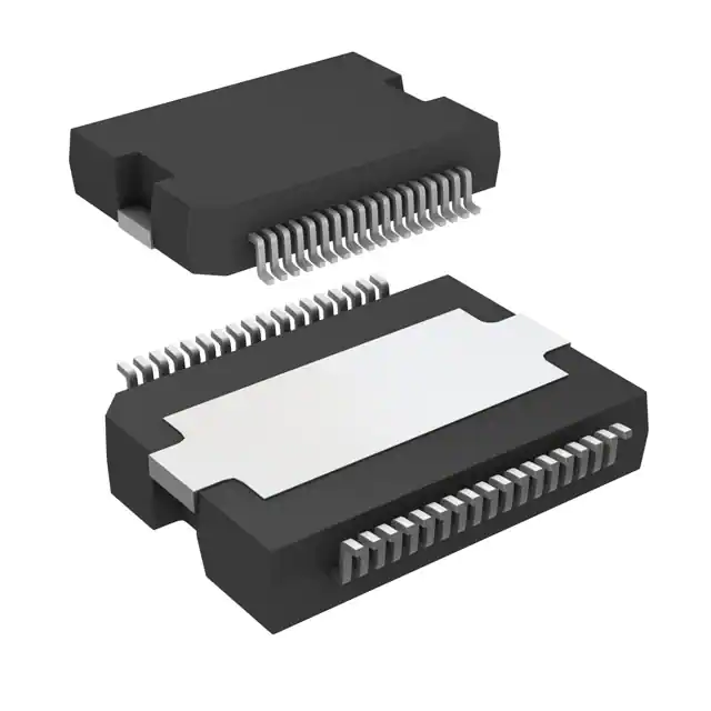
STMicroelectronics L5962TR
- Part No.:
- L5962TR
- Manufacturer:
- STMicroelectronics
- Category:
- Special Purpose Regulators
- Package:
- PowerSO-36 Exposed Top Pad
- Datasheet:
-
 L5962TR.pdf
- Description:
- IC REG CONV CAR AUD 5OUT PWRSO36
- Quantity:
- Payment:

- Shipping:

Inventory:3,595
Please send an inquiry. Send us your inquiry, and we will respond immediately.
Product details
Overview
L5962TR from STMicroelectronics is a multi-output automotive power management IC for car-radio systems, integrating one synchronous step-down switching regulator (1.2–8 V, up to 2.5 A), three programmable linear regulators (VSTBY: 3.3/5 V @ 150 mA; VLR1: 5/8.5 V @ 350 mA; VLR2: 3.3/10 V @ 1 A), two I²C-controlled high-side drivers (≤500 mV drop @ 0.5 A), reset with configurable delay, battery UV/OV detection, and load dump protection.
For engineers reviewing the L5962TR datasheet, L5962TR pinout, L5962TR application, or L5962TR equivalent, this device supports complex voltage sequencing in infotainment head units, enables standby-to-active mode transitions with ultra-low quiescent current (90 µA), provides fault-protected driver outputs for antenna/motor control, and delivers precise I²C-configurable rail selection for mixed-signal audio and DSP subsystems.
Technical Context
The L5962TR implements a BCD-process-based power SoC architecture with independent thermal shutdown per regulator and driver, synchronized switching operation (185 kHz free-run or 220–400 kHz via SYNC), and I²C-addressable configuration of VLR1/VLR2 output voltages and enable states. Its VSTBY regulator remains active during battery disconnect to preserve microcontroller RTC and memory backup.
Regulator control logic enforces hierarchical safety: overvoltage shutdown (27–31 V) disables all outputs automatically; undervoltage lockout (7–8 V) triggers RST deassertion; and each high-side driver includes short-to-battery, short-to-ground, and loss-of-ground protection with auto-recovery after fault clearance.
Key Specifications
| Parameter | Value and Actual Design Meaning |
|---|---|
| Switching Regulator Output | 1.2–8 V adjustable via external resistor divider - enables single IC to supply multiple core/logic rails |
| Max Switching Load Current | 2.5 A at VOUT = 8 V - supports high-power digital signal processors in head units |
| VSTBY Quiescent Current | 90 µA max (–40 °C to 85 °C) - sustains low-power standby mode without draining vehicle battery |
| VLR2 Output Capability | 3.3 V / 10 V @ 1 A - powers RF modules or display backlight drivers with I²C-selectable voltage |
| High-Side Driver Drop | ≤500 mV @ 0.5 A - minimizes power loss in antenna switching and sensor excitation circuits |
| I²C Bus Speed | Up to 400 kHz - allows fast configuration of regulators and drivers during boot or mode change |
| Battery UV Threshold | 7–8 V (adjustable via LVWIN pin) - prevents system operation under weak battery conditions |
Pinout & Package
Package: PowerSO36 (slug-up), thermally enhanced exposed tab requiring PCB ground connection for optimal thermal performance and EMI suppression.
| Pin/Terminal | Circuit Role | Design Meaning |
|---|---|---|
| TAB (Pin 1) | Thermal & Electrical Ground | Mandatory GND connection for heat dissipation and noise reduction; forms primary return path for switching regulator |
| PGND (Pin 2) | Power Ground Reference | Low-impedance return for switching regulator current; must be separated from AGND to avoid noise coupling |
| CBS (Pin 3) | Bootstrap Capacitor Input | Provides gate drive voltage for internal high-side NDMOS; requires ceramic capacitor ≥100 nF |
| PH (Pin 4) | Switching Phase Output | Drives external inductor; connects to PHASE node of buck converter; critical for EMI layout |
| VINsw (Pin 7) | Switching Regulator Supply | Direct battery input (VBAT) for buck stage; rated for transient up to 50 V for load dump immunity |
| HSD1/HSD2 (Pins 8, 11) | Protected High-Side Outputs | Drive external loads (e.g., antennas, relays); include short-circuit, overtemperature, and reverse-battery protection |
| VSTBYSEL (Pin 15) | Standby Regulator Selection | Ground = 3.3 V output; 5 V = 5 V output - sets VSTBY rail without firmware intervention |
| SCL/SDA (Pins 29, 24) | I²C Interface | Standard-compliant bus interface (400 kHz) for dynamic reconfiguration of VLR1/VLR2 and driver enable states |
Key Features
| Feature | Design Value |
|---|---|
| Multi-rail programmability | Three independent linear regulators + one buck regulator, all configurable via pins or I²C for flexible system partitioning |
| Automotive-grade protection | Integrated load dump immunity, ±50 V transient tolerance, and per-regulator thermal shutdown with 5–15 °C hysteresis |
| Ultra-low standby consumption | 90 µA total quiescent current ensures <10 µA/h battery drain in parked vehicle mode |
| Configurable reset timing | RSTDLY pin accepts external capacitor (100 pF typical) to set RST assertion delay from 25–75 µs for sequenced MCU startup |
| Adjustable battery monitoring | LVWIN pin sets undervoltage warning threshold from 1.225–1.275 V, enabling precise 7–8 V battery cutoff calibration |
Applications
| Car Radio Head Unit | Digital Signal Processor Power |
|---|---|
|
Use Scenario: Primary power management unit in OEM automotive infotainment head units with AM/FM/DAB tuner, Bluetooth, and USB connectivity. IC Role / Device Role / Timing Role: Central PMIC providing sequenced, protected, and monitored power to MCU, audio codec, RF front-end, and display controller. Use Value: Eliminates need for discrete LDOs and buck controllers; reduces BOM count by 7+ components while meeting ISO 7637-2 pulse 5a load dump requirements. |
Use Scenario: Dedicated power source for high-performance DSPs (e.g., TI C674x, ADI SHARC) requiring clean, stable 1.2 V core and 3.3 V I/O rails. IC Role / Device Role / Timing Role: Supplies VLR2 (3.3 V @ 1 A) and switching regulator (1.2 V via external divider) with tight load regulation (<±20 mV) and low noise (<350 µV). Use Value: Enables deterministic DSP boot timing via RST synchronization and avoids voltage droop during FFT-intensive audio processing bursts. |
| Antenna Switching Control | Backup Memory & RTC Support |
|
Use Scenario: Driving diversity antennas and tunable matching networks in DAB/DVB-T2 receivers. IC Role / Device Role / Timing Role: HSD1/HSD2 deliver controlled 12 V switching signals with short-circuit recovery and battery reverse polarity protection. Use Value: Replaces discrete high-side switches and protection ICs; reduces PCB area by 40% and eliminates external current-sense resistors. |
Use Scenario: Maintaining SRAM retention and real-time clock operation during engine-off periods. IC Role / Device Role / Timing Role: VSTBY regulator (3.3 V @ 150 mA) remains active down to 4.5 V battery with Schottky backup diode; RST confirms regulation status. Use Value: Guarantees zero data loss across ignition cycles; achieves <10 µA system standby current without external supervisor IC. |
Equivalent & Alternatives
The following parts are listed as comparable options for similar multi-rail automotive PMIC applications.
| Alternative Part | Technical Difference | Application Difference | Selection Advice |
|---|---|---|---|
| NCP380LSN33T2G | Single 3.3 V LDO (150 mA), no switching regulator or I²C interface | Only suitable for auxiliary rail generation; cannot replace full L5962TR functionality | Select only for simple backup rail supplementation where buck and driver functions are handled externally |
| TPS65381AQDAGQ1 | Three LDOs + one buck (1.2–5.5 V), but no integrated high-side drivers or battery UV/OV detection | Lacks antenna switching capability and standalone battery monitoring; requires external comparators | Choose when system uses separate driver ICs and has dedicated battery monitor; offers higher buck efficiency (92%) at light load |
Compared with NCP380LSN33T2G and TPS65381AQDAGQ1, the L5962TR uniquely integrates switching regulation, dual high-side drivers, and battery sensing in one package-enabling complete car-radio power architecture with minimal external components and guaranteed AEC-Q100 Grade 2 compliance.
Availability
L5962TR is available at Aetrix Electronics and suitable for automotive infotainment systems, telematics control units, and digital radio receivers requiring stable component supply across extended temperature ranges and long production lifecycles.
Supply support for L5962TR includes scheduled delivery planning, volume procurement assistance, BOM continuity management, traceable sourcing, and lifecycle availability coordination for OEM customers, industrial embedded developers, connected-device designers, and electronics production programs.
Manufacturer
STMicroelectronics is a global semiconductor leader specializing in automotive, industrial, and power management solutions, with over 30 years of AEC-Q100-qualified analog IC development.
The L5962TR belongs to ST's automotive PMIC portfolio designed specifically for cost-sensitive, space-constrained car-radio platforms needing integrated voltage regulation, driver outputs, and battery interface functions in a single PowerSO36 package.
FAQ
What is the minimum operating voltage for the VSTBY regulator?
The VSTBY regulator operates down to 4.5 V when using an external Schottky diode for back-up function, enabling reliable RTC and memory retention even during cranking events. Its undervoltage lockout is set at 7–8 V via the LVWIN pin, and it draws only 90 µA quiescent current across –40 °C to 85 °C.
How does the SYNC pin affect switching frequency?
The SYNC pin accepts an external clock signal to force the switching regulator's frequency between 220 kHz and 400 kHz, allowing EMI optimization and avoidance of sensitive bands. In free-run mode, it operates at 185 kHz (typical). The SYNC function maintains regulation stability and current limit accuracy across the full range.
Can VLR1 and VLR2 be enabled simultaneously with different output voltages?
Yes - VLR1 (5/8.5 V) and VLR2 (3.3/10 V) are independently controllable via I²C commands. Their output voltages are selected by register writes (e.g., IB1 byte for VLR2), and both can be active concurrently to power disparate subsystems such as audio DACs (5 V) and display interfaces (10 V) without cross-regulation interference.
What protection features apply to the high-side drivers?
HSD1 and HSD2 integrate short-to-ground, short-to-battery, loss-of-ground, and unsupplied short-to-battery protection. Each driver shuts down on fault detection and auto-recovers after thermal cooldown or fault removal. Dropout voltage remains ≤500 mV at 0.5 A, and leakage current is limited to 10 µA when disabled.
L5962TR Specifications
- Product attributes
- Attribute value
- Manufacturer:
- STMicroelectronics
- Series:
- -
- Package/Case:
- PowerSO-36 Exposed Top Pad
- Packaging:
- Tape & Reel (TR)
- Product Status:
- Active
- Applications:
- Converter, Car Audio System
- Voltage - Input:
- 4.1V ~ 27V
- Number of Outputs:
- 5
- Voltage - Output:
- Multiple
- Operating Temperature:
- -40°C ~ 85°C
- Grade:
- -
- Qualification:
- -
- Mounting Type:
- Surface Mount
- Supplier Device Package:
- PowerSO-36
L5962TR FAQ
1.How can I place an order for L5962TR through Aetrix?
Please submit a Request for Quotation (RFQ) for L5962TR on Aetrix. Our sales agent will provide a competitive quotation and guide you through the order confirmation once you accept the terms.
2.Are the price and stock information for L5962TR reliable?
The price and inventory of L5962TR are updated periodically and may fluctuate due to market conditions. Stock and pricing data are typically refreshed every 24 hours. Quotation validity for L5962TR is usually 5 days.
3.What payment methods are accepted for L5962TR?
We accept Wire Transfer, PayPal, Credit Card, Western Union, MoneyGram, and Escrow for L5962TR transactions.
Note: Certain payment methods may incur a processing fee.
4.How is shipping managed for L5962TR?
L5962TR orders can be shipped via leading logistics carriers, including DHL, UPS, FedEx, TNT, or Registered Mail.
Once your L5962TR order is processed, you will receive an email with the shipment details and tracking number.
Note: Tracking information may take up to 24 hours to appear. Express delivery typically takes 3–5 business days.
5.How can I obtain technical support or documentation for L5962TR?
For technical support, including L5962TR datasheets, pinout diagrams, or application guidance, please contact our engineering support team. They can provide detailed documentation and assistance for your L5962TR requirements.
6.How does Aetrix verify that L5962TR is sourced from the original manufacturer or authorized distributors?
All L5962TR products on Aetrix are procured from qualified distributors and authorized channels. Our dedicated quality assurance team conducts strict verification, including traceability checks and, if necessary, third-party testing. This ensures that L5962TR meets industry standards.
7.What is the process for return or replacement of L5962TR?
All L5962TR units undergo pre-shipment inspection (PSI). If there is an issue with L5962TR, returns or replacements are accepted under the following conditions:
1.Quantity discrepancies, incorrect items, or visible external defects (such as breakage or corrosion), acknowledged by Aetrix.
2.The issue is reported within 90 days of delivery.
3.The L5962TR part is unused and in its original packaging.
Return procedure for L5962TR:
1.Submit a request within 90 days.
2.Obtain a Return Material Authorization (RMA) from Aetrix.
L5962TR Tags

-
TPS51206DSQR
Texas Instruments

-
TPS51200DRCR
Texas Instruments
-
TPS51200DRCT
Texas Instruments

-
TPS62740DSSR
Texas Instruments

-
TPS51100DGQR
Texas Instruments

-
NCP51200MNTXG
onsemi
-
NCP51400MNTXG
onsemi

-
RT9026GSP
Richtek USA Inc.

-
LP2998MRX/NOPB
Texas Instruments
-
TPS51200QDRCRQ1
Texas Instruments

-
DPA423GN-TL
Power Integrations
-
LM10011SD/NOPB
Texas Instruments
Tech Hub

A practical engineering and sourcing framework covering lifecycle verification, lifetime-buy calculations, replacement qualification, supplier checks and counterfeit-risk controls.

TTL and CMOS logic families differ in thresholds, loading, output drive, power and timing. This engineering guide compares 74HC and 74HCT, calculates noise margins and checks 3.3 V/5 V compatibility.

A practical engineering guide to 3.3V and 5V logic compatibility, input thresholds, resistor dividers, translator ICs, MOSFET level shifting, I2C pull-ups, timing limits and power-sequencing risks.

The 74HC595 uses push-pull logic outputs, while the TPIC6B595 uses 50 V open-drain DMOS sinks for higher-power loads. This guide compares timing, current limits, 3.3 V interfacing, load wiring, thermal…

The 74HC595 converts serial data into eight stable parallel outputs. This guide covers pin functions, shift and storage timing, OE and MR behavior, drive-current limits, cascading, voltage compatibilit…

A technical comparison of level-sensitive latches and edge-triggered flip-flops, covering timing windows, setup and hold limits, master–slave operation, time borrowing, race-through, HDL inference and…

A D latch stores one bit while Enable controls when data can pass. This reference covers gate-level operation, truth tables, transparency, setup and hold timing, LE versus OE, common ICs and practical …

An SR latch stores one bit through cross-coupled feedback. This engineering reference covers NOR and NAND implementations, truth tables, forbidden-state recovery, gated operation, switch debouncing, fa…

Latch circuits retain one bit through feedback. This technical reference covers SR and D latches, truth tables, transparency, timing limits, latch-versus-flip-flop behavior, applications and common log…

An engineering guide to LED driver operation, constant-current and constant-voltage outputs, linear and switching topologies, dimming, IC selection, calculations, replacement compatibility, and fault c…


