
 My Inquiry
 My Account


STMicroelectronics L5991A
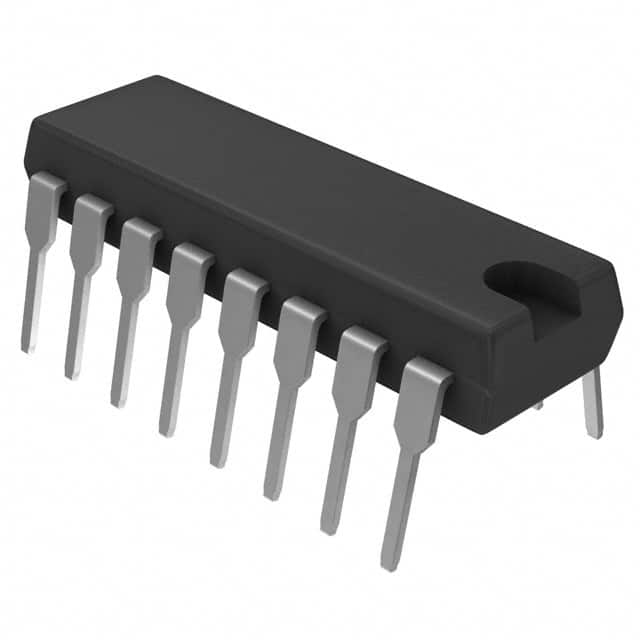
- Part No.:
- L5991A
- Manufacturer:
- STMicroelectronics
- Category:
- DC DC Switching Controllers
- Package:
- 16-DIP (0.300", 7.62mm)
- Datasheet:
-
 L5991A.pdf
- Description:
- IC REG CTRLR FLYBACK 16DIP
- Quantity:
- Payment:

- Shipping:

Inventory:1,075
Please send an inquiry. Send us your inquiry, and we will respond immediately.
Product details
Overview
L5991A from STMicroelectronics is a primary-side current-mode PWM controller IC for offline and DC-DC flyback power supplies, featuring programmable soft-start (14–26 µA charge current), 100 ns leading-edge blanking on current sense, latch-type overcurrent protection with hiccup-mode restart, and dual-frequency standby operation (fosc up to 1 MHz, fSB reduced under light load). It drives external N-channel MOSFETs with 1 A peak output current and supports IN/OUT synchronization.
For engineers reviewing the L5991A datasheet, L5991A pinout, L5991A application in flyback converters, or L5991A equivalent for AC-DC SMPS control, this page provides verified functional context, validated pin roles, confirmed timing and protection parameters, and real-world design implications for standby efficiency, duty-cycle limiting, and fault recovery behavior.
Technical Context
The L5991A implements fixed-frequency current-mode control using an internal oscillator with externally programmable RCT network, where RA//RB sets normal frequency (fosc) and RA alone sets standby frequency (fSB). Its error amplifier (2.5 V reference, 60–90 dB open-loop gain, 1.7–4 MHz bandwidth) directly controls PWM duty via COMP voltage, which also triggers standby mode when falling below VT1 = 2.5 V (rising threshold VT2 = 4.0 V).
Current sensing uses a dedicated ISEN input with 1.1–1.3 V fault threshold, 70–100 ns delay to output, and internal 100 ns blanking window. The PWM logic is fully latched with double-pulse suppression, and the 1 A totem-pole output stage includes internal clamp (13 V) and supports gate drive for discrete MOSFETs without external buffers.
Key Specifications
| Parameter | Value and Actual Design Meaning |
|---|---|
| Switching Frequency | Up to 1 MHz (externally programmable via RCT network; fSB selectable independently for light-load efficiency) |
| Start-up Current | < 120 µA (enables high-resistance start-up networks, reducing standby losses) |
| Output Drive Current | 1 A peak source/sink (directly drives power MOSFET gates without external buffer stages) |
| VREF Accuracy | 4.925–5.075 V at 25°C (±1.5% tolerance; stable over line/load/temperature for precision feedback referencing) |
| Current Sense Threshold | 1.1–1.3 V (precise overcurrent detection with 100 ns blanking to reject switching noise) |
| Soft-Start Charge Current | 14–26 µA (sets controlled ramp time for VCOMP; enables predictable inrush limiting) |
| UVLO Hysteresis | 4.5–5.0 V (VON = 7.8–8.4 V, VOFF = 7.0–7.6 V; prevents oscillation near turn-on threshold) |
| Standby Threshold | VCOMP = 2.5 V (falling) / 4.0 V (rising); hysteresis ensures stable mode transition during load transients) |
Pinout & Package
Package: DIP16 and SO16 (dual-in-line and small-outline 16-pin packages; thermal resistance 80 °C/W and 120 °C/W respectively).
| Pin/Terminal | Circuit Role | Design Meaning |
|---|---|---|
| 1 SYNC | In/Out synchronization interface | Master: delivers 4 V, 3–7 mA sync pulses; Slave: edge-triggered input with 1 V low / 3.5 V high thresholds |
| 2 RCT | Oscillator timing node | Connects external CT, RA, RB; sets fosc (RA//RB) and fSB (RA only) via dual-path charging |
| 3 DC | Duty cycle programming input | Bias 1–3 V to set max duty cycle 0–93%; <1 V disables output (non-latched) |
| 4 VREF | 5.0 V ±1.5% reference output | Supplies external circuitry; requires 0.1 µF bypass to SGND for stability |
| 5 VFB | Error amp inverting input | Receives optocoupler feedback; compared to internal 2.5 V reference |
| 6 COMP | Error amp output | Drives PWM comparator; monitored for standby activation; compensation network connects to VFB |
| 7 SS | Soft-start capacitor node | Charged at 14–26 µA; clamps COMP during startup and hiccup-mode recovery |
| 8 VCC | Signal-stage supply | UVLO-enabled (7.8–8.4 V ON); internal 25 V Zener clamp; powers internal logic |
| 9 VC | Power-stage supply | Supplies gate driver; decoupled to PGND with local bulk capacitor; optional series resistor for slew control |
| 10 OUT | High-current gate driver output | 1 A peak totem-pole; 1.0 V low / 9–10.5 V high; 13 V clamp protects against overshoot |
| 11 PGND | Power ground return | Separate from SGND to minimize noise coupling into error amplifier |
| 12 SGND | Signal ground reference | Reference for VREF, VFB, COMP, SS, DIS; must be star-connected to avoid ground bounce |
| 13 ISEN | Current sense input | Monitors primary-side current via sense resistor; 100 ns blanking window suppresses turn-on spikes |
| 14 DIS | Disable input | Active-high (2.4–2.6 V threshold); must not float; ties to SGND if unused |
| 15 DC-LIM | Duty cycle limit select | Connect to VREF → 50% max duty; floating/grounded → no limit (up to 93%) |
| 16 ST-BY | Standby mode control | Resistor-to-RCT configures standby entry; connect to VREF or float if unused |
Key Features
| Feature | Design Value |
|---|---|
| Programmable dual-frequency operation | Independent fosc and fSB set via RA/RB/CT; ratio ≤5.5 ensures stable mode transitions |
| Fully latched PWM with double-pulse suppression | Prevents multiple switching events per cycle; eliminates false triggering during transient recovery |
| Hiccup-mode overcurrent protection | Auto-restart after fault clearance; soft-start reinitiation avoids repeated stress on power components |
| 100 ns internal leading-edge blanking | Rejects MOSFET turn-on current spikes without external RC filters or delay circuits |
| IN/OUT synchronization capability | Enables multi-controller interleaving or master-slave coordination without external logic |
| Separate PGND/SGND pins | Reduces noise coupling from power-switching currents into error amplifier and reference circuits |
Applications
| AC-DC Adapter | Industrial Flyback PSU |
|---|---|
Use Scenario: 12 V/2 A isolated wall adapter for IoT sensors with strict no-load power requirements. IC Role / Device Role / Timing Role: Primary-side controller managing PWM duty, current sensing, and automatic standby frequency reduction below 10% load. Use Value: Achieves <300 mW no-load consumption via fSB scaling and <120 µA start-up current, meeting Energy Star Level VI. | Use Scenario: 24 V/5 A industrial power supply with overvoltage lockout and hiccup-mode short-circuit protection. IC Role / Device Role / Timing Role: Core timing and protection controller; DIS pin tied to OVP comparator output for immediate shutdown. Use Value: Latched disable + hiccup recovery prevents transformer saturation and MOSFET failure during sustained overload. |
| USB-C PD Auxiliary Supply | Smart Home Power Module |
Use Scenario: Auxiliary 5 V/1 A supply in USB-C PD sink design, synchronized to main controller clock. IC Role / Device Role / Timing Role: Slave-mode PWM controller synced to system master clock via SYNC pin. Use Value: Eliminates beat frequencies and EMI peaks by enforcing deterministic phase alignment across rails. | Use Scenario: Compact 12 V/0.5 A flyback for smart lighting control with remote enable/disable. IC Role / Device Role / Timing Role: Standby-optimized controller with DIS pin driven by microcontroller GPIO for scheduled power-down. Use Value: Reduces quiescent draw to <150 µA in disabled state while retaining fast wake-up (<10 ms) via soft-start reset. |
Equivalent & Alternatives
The following parts are listed as comparable options for similar primary-side PWM controller applications.
| Alternative Part | Technical Difference | Application Difference | Selection Advice |
|---|---|---|---|
| UC3844B | Fixed 52 kHz frequency; no standby mode; 1 A output; no sync pin; no programmable duty limit | Suitable for cost-sensitive fixed-frequency designs without light-load optimization needs | Select when BOM simplicity and legacy compatibility outweigh adaptive frequency benefits |
| ICE2A265 | Integrated 650 V MOSFET; fixed 65 kHz; no external RCT tuning; lower start-up current (60 µA) | Targeted at ultra-compact, low-component-count adapters; lacks ISEN blanking and hiccup mode | Choose for space-constrained consumer adapters where integration > flexibility |
Compared with UC3844B and ICE2A265, the L5991A uniquely combines programmable dual-frequency operation, precise 100 ns blanking, and hiccup-mode fault recovery-making it optimal for industrial and energy-compliant flyback designs requiring both robustness and dynamic efficiency scaling.
Availability
L5991A is available at Aetrix Electronics and suitable for AC-DC adapters, industrial flyback PSUs, and smart home power modules requiring stable component supply, long-term lifecycle support, and traceable sourcing for safety-critical implementations.
Supply support for L5991A includes scheduled delivery planning, volume procurement assistance, BOM continuity management, traceable sourcing, and lifecycle availability coordination for OEM customers, industrial embedded developers, connected-device designers, and electronics production programs.
Manufacturer
STMicroelectronics is a global semiconductor leader specializing in power management, analog, and microcontroller solutions for industrial, automotive, and consumer markets.
The L5991A belongs to ST's MultiPower BCD60II product line-designed specifically for high-voltage, high-efficiency offline SMPS controllers with integrated protection, precision timing, and adaptive light-load operation.
FAQ
What is the minimum recommended value for the RCT timing capacitor (CT) to ensure stable oscillator operation?
The datasheet specifies CT = 1 nF as the nominal value used across all electrical characteristics testing. Operation down to 100 pF is validated in Figure 14 (timing resistor vs. frequency), but below 220 pF, jitter increases significantly and standby frequency accuracy degrades. For production designs, ST recommends CT ≥ 220 pF with appropriate RA/RB selection to maintain <5% frequency deviation over temperature and supply variation.
How does the L5991A implement hiccup-mode protection, and what is the typical hiccup period under sustained short-circuit?
Hiccup mode activates when ISEN voltage exceeds 1.2 V, forcing full shutdown and initiating soft-start recharge of the SS capacitor. The hiccup period is calculated as Thic ≅ 4.5 × (1/ISSC + 1/ISSD) × Css, yielding ~120 ms for a standard 100 nF SS capacitor. During each hiccup cycle, the IC attempts one full soft-start ramp before rechecking fault status-ensuring safe, low-duty-cycle recovery without thermal runaway.
Can the L5991A be used in continuous conduction mode (CCM) flyback designs, and what compensation considerations apply?
Yes-the L5991A supports both DCM and CCM operation. In CCM, the error amplifier's 1.7–4 MHz bandwidth and 8 V/µs slew rate enable wide-loop bandwidth, but compensation must account for right-half-plane zero. ST recommends type-II or type-III networks with pole placement at fSB/4 ÷ fSB/5 to maintain stability during standby transitions, and explicit attention to PGND/SGND separation to prevent loop oscillation.
What is the maximum allowable voltage difference between VC and VCC, and why is separate decoupling critical?
The absolute maximum rating allows VC up to 25 V, same as VCC, but VC experiences high di/dt pulsed currents during MOSFET switching, while VCC draws steady logic current. Without separate 10 µF+ bulk capacitors referenced to PGND (VC) and SGND (VCC), voltage droop on VC causes shoot-through risk and VCC noise couples into COMP/VFB, inducing regulation instability or false overcurrent trips.
L5991A Specifications
- Product attributes
- Attribute value
- Manufacturer:
- STMicroelectronics
- Series:
- -
- Package/Case:
- 16-DIP (0.300", 7.62mm)
- Packaging:
- Tube
- Product Status:
- Obsolete
- Output Type:
- Transistor Driver
- Function:
- Step-Up/Step-Down
- Output Configuration:
- Positive, Isolation Capable
- Topology:
- Flyback
- Number of Outputs:
- 1
- Output Phases:
- 1
- Voltage - Supply (Vcc/Vdd):
- 7.6V ~ 20V
- Frequency - Switching:
- Up to 1MHz
- Duty Cycle (Max):
- 93%
- Synchronous Rectifier:
- Yes
- Clock Sync:
- No
- Serial Interfaces:
- -
- Control Features:
- Current Limit, Frequency Control, Soft Start
- Operating Temperature:
- -40°C ~ 150°C (TJ)
- Grade:
- -
- Qualification:
- -
- Mounting Type:
- Through Hole
- Supplier Device Package:
- 16-DIP
L5991A FAQ
1.How can I place an order for L5991A through Aetrix?
Please submit a Request for Quotation (RFQ) for L5991A on Aetrix. Our sales agent will provide a competitive quotation and guide you through the order confirmation once you accept the terms.
2.Are the price and stock information for L5991A reliable?
The price and inventory of L5991A are updated periodically and may fluctuate due to market conditions. Stock and pricing data are typically refreshed every 24 hours. Quotation validity for L5991A is usually 5 days.
3.What payment methods are accepted for L5991A?
We accept Wire Transfer, PayPal, Credit Card, Western Union, MoneyGram, and Escrow for L5991A transactions.
Note: Certain payment methods may incur a processing fee.
4.How is shipping managed for L5991A?
L5991A orders can be shipped via leading logistics carriers, including DHL, UPS, FedEx, TNT, or Registered Mail.
Once your L5991A order is processed, you will receive an email with the shipment details and tracking number.
Note: Tracking information may take up to 24 hours to appear. Express delivery typically takes 3–5 business days.
5.How can I obtain technical support or documentation for L5991A?
For technical support, including L5991A datasheets, pinout diagrams, or application guidance, please contact our engineering support team. They can provide detailed documentation and assistance for your L5991A requirements.
6.How does Aetrix verify that L5991A is sourced from the original manufacturer or authorized distributors?
All L5991A products on Aetrix are procured from qualified distributors and authorized channels. Our dedicated quality assurance team conducts strict verification, including traceability checks and, if necessary, third-party testing. This ensures that L5991A meets industry standards.
7.What is the process for return or replacement of L5991A?
All L5991A units undergo pre-shipment inspection (PSI). If there is an issue with L5991A, returns or replacements are accepted under the following conditions:
1.Quantity discrepancies, incorrect items, or visible external defects (such as breakage or corrosion), acknowledged by Aetrix.
2.The issue is reported within 90 days of delivery.
3.The L5991A part is unused and in its original packaging.
Return procedure for L5991A:
1.Submit a request within 90 days.
2.Obtain a Return Material Authorization (RMA) from Aetrix.
L5991A Tags

-
UCC28C45DR
Texas Instruments
-
UCC28C40DR
Texas Instruments
-
UCC28C43DR
Texas Instruments

-
ZXSC410E6TA
Diodes Incorporated

-
LM3524DMX/NOPB
Texas Instruments

-
LM3489MMX/NOPB
Texas Instruments
-
MIC2102YML-TR
Microchip Technology

-
LM5148RGYR
Texas Instruments
-
TL598CDR
Texas Instruments

-
LM5155DSSR
Texas Instruments

-
LM25085MYX/NOPB
Texas Instruments
-
UCC2813DTR-0
Texas Instruments
Tech Hub

Operational amplifier guide covering op amp basics, feedback, ideal vs real op amps, common configurations, buffer circuits, offset, bias current, gain-bandwidth, slew rate, rail-to-rail limits and sel…

Jumper cables guide covering safe connection order, red and black clamp placement, final ground connection, cable gauge, length, clamp quality, copper vs CCA cables, jump starter comparison and battery…

LDO regulator guide covering low dropout voltage, power dissipation, thermal design, PSRR, output noise, capacitor stability, adjustable LDO circuits, LDO vs buck converter and datasheet selection chec…

Conditional Access Module guide covering CAM meaning, CI/CI+ interface, smart card authorization, DVB security workflow, TV and set-top box compatibility, internal electronics, ESD protection, connecto…

Guide to electronic component obsolescence covering EOL risk, PCN/PDN notices, last-time buy planning, replacement options, form-fit-function validation, counterfeit risk and BOM lifecycle management.

18650 battery guide covering lithium-ion cell basics, 3.6V/3.7V voltage, 4.2V charging, mAh and Wh capacity, protected cells, chargers, BMS, series-parallel packs, holders, welding and sourcing checks.…

Hall effect sensor guide covering working principle, linear and digital sensors, Arduino circuits, current sensing, speed detection, automotive applications, A3144 examples, signal filtering and datash…

Product Change Notification guide for electronic components, covering PCN meaning, PCN vs PDN/EOL, common change types, risk levels, form-fit-function review, engineering validation, BOM control, LTB/L…

A practical guide to blend door actuators, covering HVAC function, symptoms, location, AC and heater issues, reset and calibration, replacement cost, electrical diagnosis, compatibility checks, and rep…

Engineering guide to Raspberry Pi alternatives, covering chip-level differences, Orange Pi, ROCK, Jetson, Banana Pi, NanoPi, Compute Module, Pico, GPIO, camera, HAT compatibility, and replacement risks…


