
 My Inquiry
 My Account


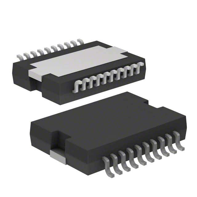
STMicroelectronics L6205PD013TR
- Part No.:
- L6205PD013TR
- Manufacturer:
- STMicroelectronics
- Category:
- Motor Drivers, Controllers
- Package:
- 20-SOIC (0.433", 11.00mm Width) Exposed Pad
- Datasheet:
-
 L6205PD013TR.pdf
- Description:
- IC MTR DRV BIPOLAR 8-52V 20PWRSO
- Quantity:
- Payment:

- Shipping:

Inventory:1,184
Please send an inquiry. Send us your inquiry, and we will respond immediately.
Product details
Overview
L6205PD013TR from STMicroelectronics is a DMOS dual full-bridge motor driver IC designed for bipolar stepper and dual/quad DC motor control, featuring 5.6A peak output current (2.8A DC), 0.34Ω typical high-side RDS(ON) at 25°C, 8–52V operating supply voltage, non-dissipative overcurrent protection, and integrated fast freewheeling diodes. It operates up to 100kHz switching frequency and supports paralleled operation for higher current or lower dissipation.
For engineers reviewing the L6205PD013TR datasheet, L6205PD013TR pinout, L6205PD013TR application, or L6205PD013TR equivalent, key selection criteria include bridge enable logic behavior, bootstrap charge pump timing (600kHz VCP output), thermal shutdown threshold (165°C), dead-time protection (0.5–1µs), and SENSEA/SENSEB current-sense architecture without external shunts.
Technical Context
The L6205PD013TR integrates two independent DMOS full bridges with matched high-side and low-side N-channel power transistors, each with intrinsic fast freewheeling diodes and 0.34Ω/0.28Ω (HS/LS) RDS(ON) at 25°C. Cross-conduction prevention uses programmable dead time (0.5–1µs) between complementary switch transitions per leg.
It employs an internal charge pump (VCP output @ 600kHz, 10V amplitude) to generate VBOOT for high-side gate drive above VS, enabling N-MOS upper switches. Overcurrent detection is non-dissipative, sensing fractional current directly from high-side DMOS cells and triggering EN pin pull-down via open-drain MOSFET when ISOVER ≥ 5.6A (typ).
Key Specifications
| Parameter | Value and Actual Design Meaning |
|---|---|
| Supply Voltage Range | 8–52V - Supports wide industrial DC bus voltages including 24V and 48V systems without external regulation. |
| Peak Output Current | 5.6A - Enables driving high-torque bipolar stepper motors or dual DC motors under pulse load. |
| RDS(ON) (HS, 25°C) | 0.34Ω typ - Limits conduction loss to ~5.4W per high-side switch at 4A RMS, critical for thermal design. |
| Switching Frequency | Up to 100kHz - Allows fine PWM resolution for smooth microstepping and torque control in stepper applications. |
| Thermal Shutdown | 165°C (typ), 15°C hysteresis - Protects die during overload or poor heatsinking; recovery requires junction cooldown below 150°C. |
| OCD Threshold | 5.6A (typ) - Triggers fault response without external sense resistor, eliminating shunt power loss and PCB area. |
| VCP Frequency | 600kHz (typ) - Drives external bootstrap capacitor (CBOOT = 220nF) to sustain VBOOT > VS + 10V for reliable high-side turn-on. |
Pinout & Package
Package: PowerSO-20 (exposed thermal slug, pins 1/10/11/20 internally connected to GND). Designed for surface-mount assembly with bottom-side copper thermal pad soldering to PCB ground plane.
| Pin/Terminal | Circuit Role | Design Meaning |
|---|---|---|
| IN1A / IN2A / IN1B / IN2B | Bridge Logic Inputs | TTL/CMOS-compatible control signals defining H-bridge direction per channel (e.g., IN1A=H/IN2A=L → OUT1A=VS, OUT2A=GND). |
| ENA / ENB | Bridge Enable Inputs | Active-high enables respective bridge; also serve as OCD fault outputs-internally pulled low (<1.3V) during overcurrent. |
| SENSEA / SENSEB | Current Sense Reference | Connect directly to power ground (or low-value sense resistor); source internal current proportional to bridge output current. |
| VSA / VSB | Bridge Power Supplies | Independent 8–52V inputs for Bridge A and B; must be tied together externally for single-supply operation. |
| OUT1A / OUT2A / OUT1B / OUT2B | Power Outputs | Four high-current terminals (5.6A peak) forming two independent full H-bridges for bidirectional motor winding control. |
| VBOOT | Bootstrap Supply | Accepts charge-pump voltage (VS + 10V max) to drive high-side gates; requires external CBOOT (220nF) and diode. |
| VCP | Charge Pump Oscillator | 600kHz square wave output (10V amplitude) driving external CP (10nF) and RP (100Ω) to generate VBOOT. |
| GND (Pins 1,10,11,20) | Signal & Thermal Ground | Four dedicated ground pins; slug connection enables low Rth-j-amb (~15°C/W with vias + ground plane). |
Key Features
| Feature | Design Value |
|---|---|
| Non-dissipative overcurrent protection | Eliminates need for external current-sense resistors and associated power loss, simplifying layout and improving efficiency. |
| Integrated fast freewheeling diodes | Reduces external component count and PCB footprint; diode VF = 1.15–1.3V enables efficient energy recirculation during PWM decay. |
| Programmable fault recovery timing | External REN/CEN on ENA/ENB set tDISABLE (e.g., 100kΩ + 5.6nF = 200µs) and tDELAY (CEN-dependent) for controlled restart after OCD. |
| Cross-conduction protection | Hardware-enforced 0.5–1µs dead time prevents shoot-through during PWM transitions, ensuring safe bridge commutation. |
| Thermal shutdown with hysteresis | 165°C trip + 15°C hysteresis avoids oscillation during thermal stress; allows automatic recovery once junction cools to ≤150°C. |
Applications
| Bipolar Stepper Motor Control | Dual DC Motor Drive |
|---|---|
Use Scenario: Driving 2-phase bipolar stepper motors in CNC positioning stages requiring precise microstepping and high holding torque. IC Role / Device Role / Timing Role: Dual full-bridge driver providing independent phase current control with synchronized PWM and non-dissipative current limiting. Use Value: Enables 5.6A peak phase current without external sense resistors, reducing board area and thermal overhead while supporting 100kHz step rates. | Use Scenario: Controlling two independent brushed DC motors in robotic joint actuators or automated guided vehicles (AGVs). IC Role / Device Role / Timing Role: Dual H-bridge interface translating MCU GPIO commands into bidirectional motor rotation and braking with regenerative freewheeling. Use Value: Delivers 2.8A continuous per motor (5.6A peak) with integrated diodes and thermal protection, eliminating discrete flyback diodes and thermal monitoring circuits. |
| Quad Motor Systems | Paralleled High-Current Bridge |
Use Scenario: Operating four independent DC motors in compact industrial valve actuators or multi-axis lab equipment. IC Role / Device Role / Timing Role: Single-chip solution implementing four half-bridges (via INx/ENx configuration) for independent motor control with shared power rails. Use Value: Reduces component count vs. four single-channel drivers; leverages internal cross-conduction protection and unified thermal management. | Use Scenario: High-power linear actuator requiring >5A RMS current with minimal conduction loss and robust fault handling. IC Role / Device Role / Timing Role: Two L6205 bridges paralleled per half-bridge (e.g., OUT1A || OUT1B) to achieve 0.15Ω effective RDS(ON) and 11.2A OCD threshold. Use Value: Doubles current capability while maintaining matched device characteristics and single-chip control logic, avoiding inter-device timing skew. |
Equivalent & Alternatives
The following parts are listed as comparable options for similar dual full-bridge motor driver applications.
| Alternative Part | Technical Difference | Application Difference | Selection Advice |
|---|---|---|---|
| TB6612FNG | Lower voltage (4.5–13.5V), lower current (1.2A RMS), no bootstrap circuit - uses internal charge pump for high-side drive. | Suitable only for low-voltage robotics and small DC motors; lacks 52V capability and non-dissipative OCD. | Select when supply is <15V and thermal budget is tight; avoid for industrial 24/48V stepper systems. |
| VNH7040AS | Single-channel high-side/low-side driver (not dual bridge); 60V rating, 14A peak, integrated current sense but dissipative (external shunt required). | Requires two devices for dual-bridge function; adds complexity in layout and control synchronization. | Choose for ultra-high reliability automotive applications needing ASIL-B compliance; not drop-in for L6205's dual-bridge topology. |
Compared with TB6612FNG and VNH7040AS, the L6205PD013TR uniquely combines 52V operation, dual-bridge integration, non-dissipative overcurrent protection, and bootstrap-based high-side drive - making it optimal for industrial stepper and dual-motor systems where voltage range, fault resilience, and component count are critical.
Availability
L6205PD013TR is available at Aetrix Electronics and suitable for industrial motion control, CNC equipment, and automated machinery requiring stable component supply across extended temperature ranges and long production lifecycles.
Supply support for L6205PD013TR includes scheduled delivery planning, volume procurement assistance, BOM continuity management, traceable sourcing, and lifecycle availability coordination for OEM customers, industrial embedded developers, connected-device designers, and electronics production programs.
Manufacturer
STMicroelectronics is a global semiconductor leader headquartered in Geneva, Switzerland, specializing in power management, motor control, and automotive-grade ICs with vertical manufacturing capabilities.
The L6205 belongs to ST's MultiPower-BCD motor driver product line, engineered specifically for high-efficiency, high-voltage DC and stepper motor control in industrial automation and factory equipment.
FAQ
What is the recommended external capacitor value for the VCP oscillator output?
The datasheet specifies a 10nF ceramic capacitor (CP) between VCP and ground, paired with a 100Ω resistor (RP) to form the charge pump timing network. This combination ensures stable 600kHz oscillation and proper VBOOT voltage generation for high-side gate drive. Deviations may cause insufficient bootstrap voltage or erratic switching behavior.
How does the non-dissipative overcurrent protection work without a sense resistor?
The L6205PD013TR embeds precision current-mirroring circuitry within each high-side DMOS cell, delivering a scaled replica (1/n) of the output current to the SENSEA/SENSEB pins. This internal sensing eliminates external shunts while maintaining accurate 5.6A (typ) trip threshold and fast 200ns OCD response time.
Can ENA and ENB be tied together for synchronous bridge enable?
Yes - ENA and ENB can be driven by a common signal to enable both bridges simultaneously. However, doing so forfeits independent fault isolation: an overcurrent on Bridge A will disable both bridges. For independent operation, use separate REN/CEN networks and monitor each EN pin individually.
What thermal resistance can be achieved with the PowerSO-20 package on a standard PCB?
With the PowerSO-20's exposed thermal slug soldered to a 6cm² copper area (35µm thick) on a multilayer FR4 board using 16 thermal vias to an internal ground plane, Rth-j-amb is 15°C/W (typ). This enables 2.8A RMS operation at 24V without forced air cooling, assuming ambient ≤70°C and max Tj = 125°C.
L6205PD013TR Specifications
- Product attributes
- Attribute value
- Manufacturer:
- STMicroelectronics
- Series:
- STSPIN L62
- Package/Case:
- 20-SOIC (0.433", 11.00mm Width) Exposed Pad
- Packaging:
- Tape & Reel (TR)
- Product Status:
- Active
- Motor Type - Stepper:
- Bipolar
- Motor Type - AC, DC:
- Brushed DC
- Function:
- Driver - Fully Integrated, Control and Power Stage
- Output Configuration:
- Half Bridge (4)
- Interface:
- Parallel
- Technology:
- BiCDMOS
- Step Resolution:
- -
- Applications:
- General Purpose
- Current - Output:
- 2.8A
- Voltage - Supply:
- 8V ~ 52V
- Voltage - Load:
- 8V ~ 52V
- Operating Temperature:
- -25°C ~ 125°C (TJ)
- Grade:
- -
- Qualification:
- -
- Mounting Type:
- Surface Mount
- Supplier Device Package:
- PowerSO-20
L6205PD013TR FAQ
1.How can I place an order for L6205PD013TR through Aetrix?
Please submit a Request for Quotation (RFQ) for L6205PD013TR on Aetrix. Our sales agent will provide a competitive quotation and guide you through the order confirmation once you accept the terms.
2.Are the price and stock information for L6205PD013TR reliable?
The price and inventory of L6205PD013TR are updated periodically and may fluctuate due to market conditions. Stock and pricing data are typically refreshed every 24 hours. Quotation validity for L6205PD013TR is usually 5 days.
3.What payment methods are accepted for L6205PD013TR?
We accept Wire Transfer, PayPal, Credit Card, Western Union, MoneyGram, and Escrow for L6205PD013TR transactions.
Note: Certain payment methods may incur a processing fee.
4.How is shipping managed for L6205PD013TR?
L6205PD013TR orders can be shipped via leading logistics carriers, including DHL, UPS, FedEx, TNT, or Registered Mail.
Once your L6205PD013TR order is processed, you will receive an email with the shipment details and tracking number.
Note: Tracking information may take up to 24 hours to appear. Express delivery typically takes 3–5 business days.
5.How can I obtain technical support or documentation for L6205PD013TR?
For technical support, including L6205PD013TR datasheets, pinout diagrams, or application guidance, please contact our engineering support team. They can provide detailed documentation and assistance for your L6205PD013TR requirements.
6.How does Aetrix verify that L6205PD013TR is sourced from the original manufacturer or authorized distributors?
All L6205PD013TR products on Aetrix are procured from qualified distributors and authorized channels. Our dedicated quality assurance team conducts strict verification, including traceability checks and, if necessary, third-party testing. This ensures that L6205PD013TR meets industry standards.
7.What is the process for return or replacement of L6205PD013TR?
All L6205PD013TR units undergo pre-shipment inspection (PSI). If there is an issue with L6205PD013TR, returns or replacements are accepted under the following conditions:
1.Quantity discrepancies, incorrect items, or visible external defects (such as breakage or corrosion), acknowledged by Aetrix.
2.The issue is reported within 90 days of delivery.
3.The L6205PD013TR part is unused and in its original packaging.
Return procedure for L6205PD013TR:
1.Submit a request within 90 days.
2.Obtain a Return Material Authorization (RMA) from Aetrix.
L6205PD013TR Tags

-
DRV2603RUNR
Texas Instruments

-
DRV8837CDSGR
Texas Instruments

-
DRV8837DSGR
Texas Instruments
-
DRV8838DSGR
Texas Instruments

-
DRV8839DSSR
Texas Instruments

-
EMC2301-1-ACZL-TR
Microchip Technology
-
DRV8231ADSGR
Texas Instruments

-
EMC2302-2-AIZL-TR
Microchip Technology

-
DRV8800PWPR
Texas Instruments
-
DRV8835DSSR
Texas Instruments

-
EMC2303-1-KP-TR
Microchip Technology

-
DRV8876PWPR
Texas Instruments
Tech Hub

Operational amplifier guide covering op amp basics, feedback, ideal vs real op amps, common configurations, buffer circuits, offset, bias current, gain-bandwidth, slew rate, rail-to-rail limits and sel…

Jumper cables guide covering safe connection order, red and black clamp placement, final ground connection, cable gauge, length, clamp quality, copper vs CCA cables, jump starter comparison and battery…

LDO regulator guide covering low dropout voltage, power dissipation, thermal design, PSRR, output noise, capacitor stability, adjustable LDO circuits, LDO vs buck converter and datasheet selection chec…

Conditional Access Module guide covering CAM meaning, CI/CI+ interface, smart card authorization, DVB security workflow, TV and set-top box compatibility, internal electronics, ESD protection, connecto…

Guide to electronic component obsolescence covering EOL risk, PCN/PDN notices, last-time buy planning, replacement options, form-fit-function validation, counterfeit risk and BOM lifecycle management.

18650 battery guide covering lithium-ion cell basics, 3.6V/3.7V voltage, 4.2V charging, mAh and Wh capacity, protected cells, chargers, BMS, series-parallel packs, holders, welding and sourcing checks.…

Hall effect sensor guide covering working principle, linear and digital sensors, Arduino circuits, current sensing, speed detection, automotive applications, A3144 examples, signal filtering and datash…

Product Change Notification guide for electronic components, covering PCN meaning, PCN vs PDN/EOL, common change types, risk levels, form-fit-function review, engineering validation, BOM control, LTB/L…

A practical guide to blend door actuators, covering HVAC function, symptoms, location, AC and heater issues, reset and calibration, replacement cost, electrical diagnosis, compatibility checks, and rep…

Engineering guide to Raspberry Pi alternatives, covering chip-level differences, Orange Pi, ROCK, Jetson, Banana Pi, NanoPi, Compute Module, Pico, GPIO, camera, HAT compatibility, and replacement risks…


