
 My Inquiry
 My Account


STMicroelectronics L6225PDTR
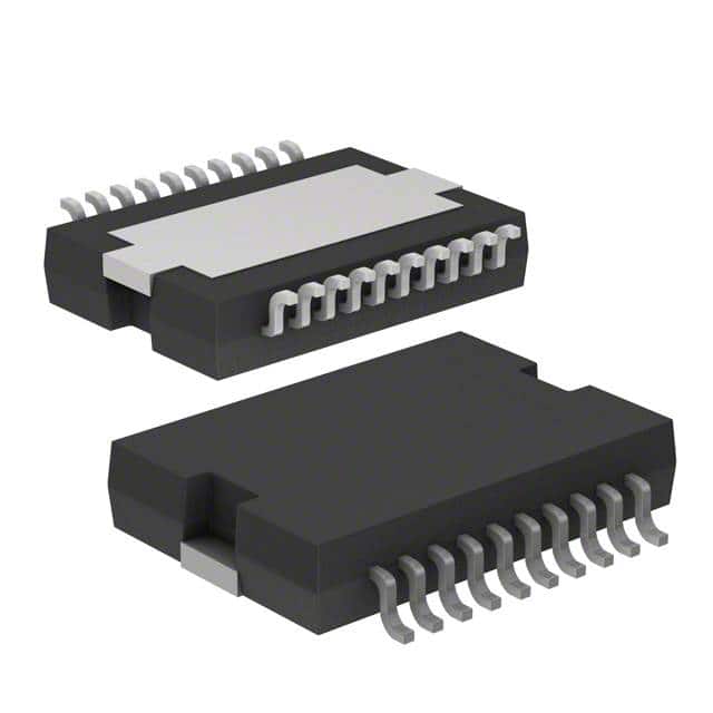
- Part No.:
- L6225PDTR
- Manufacturer:
- STMicroelectronics
- Category:
- Motor Drivers, Controllers
- Package:
- 20-SOIC (0.433", 11.00mm Width) Exposed Pad
- Datasheet:
-
 L6225PDTR.pdf
- Description:
- IC MTR DRV BIPOLAR 8-52V 20PWRSO
- Quantity:
- Payment:

- Shipping:

Inventory:1,406
Please send an inquiry. Send us your inquiry, and we will respond immediately.
Product details
Overview
L6225PDTR from STMicroelectronics is a DMOS dual full-bridge motor driver IC designed for bipolar stepper and dual/quad DC motor control, featuring 8–52 V operating supply voltage, 2.8 A peak output current (1.4 A DC), 0.73 Ω typical RDS(ON) per switch at Tj = 25 °C, up to 100 kHz switching frequency, and integrated non-dissipative overcurrent protection. It operates in PowerSO-20 package with exposed thermal slug.
For engineers reviewing the L6225PDTR datasheet, L6225PDTR pinout, L6225PDTR application, or L6225PDTR equivalent, key selection criteria include bridge enable logic behavior, bootstrap charge pump operation (VCP = 600 kHz typ.), cross-conduction dead time (0.5–1 µs), thermal shutdown at 165 °C, and ENA/ENB pin dual-role functionality (enable + OCD fault reporting).
Technical Context
The L6225PDTR integrates two independent full H-bridges using MultiPower-BCD technology, combining isolated DMOS power transistors with CMOS/bipolar logic on a single die. Each bridge supports TTL/CMOS-compatible inputs (IN1A/IN2A/IN1B/IN2B) and separate enable pins (ENA/ENB) that also serve as open-drain fault outputs for overcurrent and thermal events.
Its charge pump (VCP output, 600 kHz typ., 10 V amplitude) generates VBOOT to drive high-side N-channel MOSFETs; cross-conduction is prevented by built-in 0.5–1 µs dead time. Overcurrent detection uses internal current-sensing cells (not external shunts), triggering ENx pull-down when load current exceeds 2.8 A (typ.) per bridge.
Key Specifications
| Parameter | Value and Actual Design Meaning |
|---|---|
| Supply Voltage | 8–52 V - supports wide industrial DC bus ranges including 12 V, 24 V, and 48 V systems. |
| Peak Output Current | 2.8 A per bridge - enables driving 2-phase bipolar stepper motors up to ~1.5 A/phase RMS. |
| RDS(ON) (HS+LS) | 1.47 Ω typ. @ 25 °C - determines conduction loss; total bridge resistance defines I²R heating at 1.4 A DC. |
| Switching Frequency | Up to 100 kHz - allows high-resolution PWM current control without audible noise in motor applications. |
| Thermal Shutdown | 165 °C (15 °C hysteresis) - protects die during overload or poor PCB heat sinking; requires Rth-j-amb ≤ 36 °C/W for safe 125 °C Tj. |
| OCD Threshold | 2.8 A typ. per bridge - non-dissipative sensing eliminates external sense resistor and associated power loss. |
| Charge Pump Freq. | 0.6–1 MHz - drives external bootstrap network (CBOOT, CP, D1, D2, RP) to sustain high-side gate drive above VS. |
Pinout & Package
Package: PowerSO-20 (exposed thermal slug, internally connected to pins 1, 10, 11, 20 - all GND). Thermal resistance: Rth-j-case = 2 °C/W; Rth-j-amb = 36 °C/W with 6 cm² top-side copper + ground layer + 16 vias.
| Pin/Terminal | Circuit Role | Design Meaning |
|---|---|---|
| ENA / ENB | Bridge A/B Enable + OCD Fault Output | Active-high enable; pulled low (≤1.3 V) during overcurrent/thermal fault - requires external R-C (100 kΩ + 5.6 nF) to set recovery delay. |
| IN1A / IN2A / IN1B / IN2B | Bridge Logic Inputs | TTL/CMOS-compatible; define H-bridge state (H-H, H-L, L-H, L-L); thresholds: Vth(ON) = 1.8 V, Vth(OFF) = 1.3 V. |
| OUT1A / OUT2A / OUT1B / OUT2B | Power Outputs | DMOS drain terminals; each pair forms one full H-bridge; support paralleling for higher current or lower RDS(ON). |
| SENSEA / SENSEB | Bridge Source Sensing | Connect directly to power ground or via low-value sense resistor; used for internal OCD current sampling. |
| VSA / VSB | Bridge Power Supplies | Independent 8–52 V inputs per bridge; must be tied together externally for dual-motor operation. |
| VBOOT | Bootstrap Supply | Drives high-side gates; generated by internal oscillator (VCP) + external charge pump components. |
| VCP | Charge Pump Oscillator | 600 kHz square wave (10 V amplitude); drives external diode-capacitor network to generate VBOOT. |
Key Features
| Feature | Design Value |
|---|---|
| Non-dissipative overcurrent protection | Eliminates external current-sense resistor and its power loss; detects fault via internal high-side current mirror. |
| Integrated fast freewheeling diodes | Reduces need for external catch diodes; enables efficient slow-decay PWM motor control without added BOM cost. |
| Cross-conduction protection | Hardware-enforced 0.5–1 µs dead time prevents shoot-through during bridge switching transitions. |
| Paralleled operation support | Four half-bridges can be reconfigured as single high-current full bridge (RDS(ON) = 0.37 Ω typ.) or half bridge (0.18 Ω). |
| Thermal shutdown with hysteresis | Shuts down at 165 °C junction temp; restarts at ~150 °C - prevents thermal runaway during transient overloads. |
Applications
| Bipolar Stepper Motor Control | Dual DC Motor Drive |
|---|---|
|
Use Scenario: Driving 2-phase bipolar stepper motors in CNC positioning stages, 3D printer axes, or automated lab equipment requiring precise microstepping. IC Role / Device Role / Timing Role: Dual full-bridge driver providing independent phase current control; supports PWM current regulation up to 100 kHz for smooth motion and reduced resonance. Use Value: Integrated OCD and thermal protection eliminate external fault monitoring circuitry; RDS(ON) < 1.5 Ω ensures < 2 W conduction loss at 1.4 A DC per bridge. |
Use Scenario: Simultaneous bidirectional control of two DC motors in robotic arms, conveyor systems, or battery-powered mobility platforms. IC Role / Device Role / Timing Role: Two independent full H-bridges enabling forward/reverse/brake/coast states per motor; ENA/ENB allow synchronized or independent enable/disable. Use Value: Bootstrap charge pump (VCP) sustains high-side drive across full 8–52 V range; paralleled configuration supports 2.8 A RMS per motor with shared thermal management. |
| Quad DC Motor Interface | Industrial Actuator Driver |
|
Use Scenario: Controlling four independent brushed DC actuators in HVAC damper banks, medical infusion pumps, or smart building valve systems. IC Role / Device Role / Timing Role: Configured as four half-bridges (via pin remapping) to drive unidirectional loads; each OUTx serves as high-side switch with integrated freewheeling path. Use Value: Eliminates need for four discrete half-bridge ICs; single PowerSO-20 package reduces PCB area and interconnect complexity while maintaining 2.8 A OCD threshold per channel. |
Use Scenario: High-reliability linear actuator control in factory automation, where EMI immunity and fault resilience are critical. IC Role / Device Role / Timing Role: Full-bridge driver with robust ENx fault signaling; OCD response time < 200 ns and thermal shutdown at 165 °C ensure fail-safe operation under short-circuit conditions. Use Value: Exposed thermal slug (Rth-j-case = 2 °C/W) enables direct heatsinking to metal chassis; supports continuous 1.4 A DC with minimal board copper (6 cm² + vias). |
Equivalent & Alternatives
The following parts are listed as comparable options for similar dual full-bridge motor driver applications.
| Alternative Part | Technical Difference | Application Difference | Selection Advice |
|---|---|---|---|
| TB6612FNG | Lower voltage (2.5–13.5 V), lower current (1.2 A peak), no bootstrap - uses internal charge pump for high-side drive. | Suitable only for low-voltage robotics (e.g., 3.3 V/5 V MCU-controlled small DC motors), not for 24/48 V industrial loads. | Select if operating below 13.5 V and space-constrained; avoid for >15 V or >1.2 A applications. |
| VNQ5E050AKTR-E | Single-channel high-side switch (not full bridge); 40 V max, 5 A peak, SPI-controlled; no integrated freewheeling diodes. | Requires external H-bridge topology and flyback diodes; suited for distributed high-side switching, not integrated dual-bridge motor control. | Choose only for modular, SPI-configurable high-side switching; not a functional replacement for L6225PDTR's dual full-bridge capability. |
Compared with TB6612FNG and VNQ5E050AKTR-E, the L6225PDTR uniquely delivers dual full-bridge operation at 8–52 V with non-dissipative OCD, making it irreplaceable for industrial bipolar stepper and dual-motor systems requiring robust fault handling and wide supply range.
Availability
L6225PDTR is available at Aetrix Electronics and suitable for bipolar stepper motor control, dual DC motor drive, quad actuator interface, and industrial actuator driver applications requiring stable component supply across extended temperature and voltage ranges.
Supply support for L6225PDTR includes scheduled delivery planning, volume procurement assistance, BOM continuity management, traceable sourcing, and lifecycle availability coordination for OEM customers, industrial embedded developers, connected-device designers, and electronics production programs.
Manufacturer
STMicroelectronics is a global semiconductor leader headquartered in Geneva, Switzerland, designing and manufacturing analog, mixed-signal, power, and microcontroller products for industrial, automotive, and consumer markets.
The L6225PDTR belongs to ST's Power Switches & Motor Drivers product line, engineered specifically for ruggedized, high-efficiency motor control in industrial automation, robotics, and precision motion systems.
FAQ
What is the recommended external charge pump configuration for L6225PDTR?
Use CBOOT = 220 nF, CP = 10 nF, RP = 100 Ω, and two 1N4148 diodes. The internal VCP oscillator (600 kHz typ., 10 V) drives this network to generate VBOOT ≥ VS + 10 V. Mount components within 5 mm of the IC with short traces to minimize ringing and ensure reliable high-side gate drive across the full 8–52 V supply range.
How does the non-dissipative overcurrent protection work without an external sense resistor?
The L6225PDTR embeds precision current-mirror cells in each high-side DMOS source path. These deliver a scaled replica (1/n) of the output current to internal comparators referenced against 2.8 A threshold. When exceeded, ENA/ENB are actively pulled low (≤1.3 V) via 4 mA open-drain MOSFETs - eliminating external shunt resistors and their associated power loss and layout sensitivity.
Can L6225PDTR drive a single 4-phase unipolar stepper motor?
No - the L6225PDTR is optimized for bipolar stepper motors (2-phase, 4-wire) or dual DC motors. Unipolar steppers require center-tapped windings and separate low-side switching per phase, which this dual full-bridge topology does not support. For unipolar applications, discrete low-side drivers (e.g., ULN2003) or dedicated unipolar controllers are required.
What PCB layout practices are critical for thermal performance in PowerSO-20 package?
Solder the exposed thermal slug (pins 1, 10, 11, 20) to ≥6 cm² of 35 µm-thick copper on the top layer, connected via ≥16 thermal vias (0.3 mm diameter) to an internal ground plane. Keep SENSEA/SENSEB traces short and direct to power ground; separate power and signal ground planes with single-point connection near GND pins to avoid noise coupling into OCD sensing paths.
L6225PDTR Specifications
- Product attributes
- Attribute value
- Manufacturer:
- STMicroelectronics
- Series:
- STSPIN L62
- Package/Case:
- 20-SOIC (0.433", 11.00mm Width) Exposed Pad
- Packaging:
- Tape & Reel (TR)
- Product Status:
- Active
- Motor Type - Stepper:
- Bipolar
- Motor Type - AC, DC:
- Brushed DC
- Function:
- Driver - Fully Integrated, Control and Power Stage
- Output Configuration:
- Half Bridge (4)
- Interface:
- Parallel
- Technology:
- BiCDMOS
- Step Resolution:
- -
- Applications:
- General Purpose
- Current - Output:
- 1.4A
- Voltage - Supply:
- 8V ~ 52V
- Voltage - Load:
- 8V ~ 52V
- Operating Temperature:
- -25°C ~ 125°C (TJ)
- Grade:
- -
- Qualification:
- -
- Mounting Type:
- Surface Mount
- Supplier Device Package:
- PowerSO-20
L6225PDTR FAQ
1.How can I place an order for L6225PDTR through Aetrix?
Please submit a Request for Quotation (RFQ) for L6225PDTR on Aetrix. Our sales agent will provide a competitive quotation and guide you through the order confirmation once you accept the terms.
2.Are the price and stock information for L6225PDTR reliable?
The price and inventory of L6225PDTR are updated periodically and may fluctuate due to market conditions. Stock and pricing data are typically refreshed every 24 hours. Quotation validity for L6225PDTR is usually 5 days.
3.What payment methods are accepted for L6225PDTR?
We accept Wire Transfer, PayPal, Credit Card, Western Union, MoneyGram, and Escrow for L6225PDTR transactions.
Note: Certain payment methods may incur a processing fee.
4.How is shipping managed for L6225PDTR?
L6225PDTR orders can be shipped via leading logistics carriers, including DHL, UPS, FedEx, TNT, or Registered Mail.
Once your L6225PDTR order is processed, you will receive an email with the shipment details and tracking number.
Note: Tracking information may take up to 24 hours to appear. Express delivery typically takes 3–5 business days.
5.How can I obtain technical support or documentation for L6225PDTR?
For technical support, including L6225PDTR datasheets, pinout diagrams, or application guidance, please contact our engineering support team. They can provide detailed documentation and assistance for your L6225PDTR requirements.
6.How does Aetrix verify that L6225PDTR is sourced from the original manufacturer or authorized distributors?
All L6225PDTR products on Aetrix are procured from qualified distributors and authorized channels. Our dedicated quality assurance team conducts strict verification, including traceability checks and, if necessary, third-party testing. This ensures that L6225PDTR meets industry standards.
7.What is the process for return or replacement of L6225PDTR?
All L6225PDTR units undergo pre-shipment inspection (PSI). If there is an issue with L6225PDTR, returns or replacements are accepted under the following conditions:
1.Quantity discrepancies, incorrect items, or visible external defects (such as breakage or corrosion), acknowledged by Aetrix.
2.The issue is reported within 90 days of delivery.
3.The L6225PDTR part is unused and in its original packaging.
Return procedure for L6225PDTR:
1.Submit a request within 90 days.
2.Obtain a Return Material Authorization (RMA) from Aetrix.
L6225PDTR Tags

-
DRV2603RUNR
Texas Instruments

-
DRV8837CDSGR
Texas Instruments

-
DRV8837DSGR
Texas Instruments
-
DRV8838DSGR
Texas Instruments

-
DRV8839DSSR
Texas Instruments

-
EMC2301-1-ACZL-TR
Microchip Technology
-
DRV8231ADSGR
Texas Instruments

-
EMC2302-2-AIZL-TR
Microchip Technology

-
DRV8800PWPR
Texas Instruments
-
DRV8835DSSR
Texas Instruments

-
EMC2303-1-KP-TR
Microchip Technology

-
DRV8876PWPR
Texas Instruments
Tech Hub

An engineering guide to LED driver operation, constant-current and constant-voltage outputs, linear and switching topologies, dimming, IC selection, calculations, replacement compatibility, and fault c…

Operational amplifier guide covering op amp basics, feedback, ideal vs real op amps, common configurations, buffer circuits, offset, bias current, gain-bandwidth, slew rate, rail-to-rail limits and sel…

Jumper cables guide covering safe connection order, red and black clamp placement, final ground connection, cable gauge, length, clamp quality, copper vs CCA cables, jump starter comparison and battery…

LDO regulator guide covering low dropout voltage, power dissipation, thermal design, PSRR, output noise, capacitor stability, adjustable LDO circuits, LDO vs buck converter and datasheet selection chec…

Conditional Access Module guide covering CAM meaning, CI/CI+ interface, smart card authorization, DVB security workflow, TV and set-top box compatibility, internal electronics, ESD protection, connecto…

Guide to electronic component obsolescence covering EOL risk, PCN/PDN notices, last-time buy planning, replacement options, form-fit-function validation, counterfeit risk and BOM lifecycle management.

18650 battery guide covering lithium-ion cell basics, 3.6V/3.7V voltage, 4.2V charging, mAh and Wh capacity, protected cells, chargers, BMS, series-parallel packs, holders, welding and sourcing checks.…

Hall effect sensor guide covering working principle, linear and digital sensors, Arduino circuits, current sensing, speed detection, automotive applications, A3144 examples, signal filtering and datash…

Product Change Notification guide for electronic components, covering PCN meaning, PCN vs PDN/EOL, common change types, risk levels, form-fit-function review, engineering validation, BOM control, LTB/L…

A practical guide to blend door actuators, covering HVAC function, symptoms, location, AC and heater issues, reset and calibration, replacement cost, electrical diagnosis, compatibility checks, and rep…


