
 My Inquiry
 My Account


STMicroelectronics L6360TR
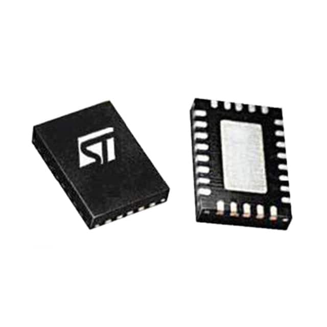
- Part No.:
- L6360TR
- Manufacturer:
- STMicroelectronics
- Category:
- Drivers, Receivers, Transceivers
- Package:
- 26-VFQFN Exposed Pad
- Datasheet:
-
 L6360TR.pdf
- Description:
- IC TRANSCEIVER 1/1 26VFQFPN
- Quantity:
- Payment:

- Shipping:

Inventory:4,999
Please send an inquiry. Send us your inquiry, and we will respond immediately.
Product details
Overview
L6360TR from STMicroelectronics is an IO-Link master transceiver IC compliant with PHY2 (3-wire) and supporting COM1 (4.8 kbaud), COM2 (38.4 kbaud), and COM3 (230.4 kbaud) modes. It integrates programmable high-side/low-side/push-pull C/QO output stages (< 2 Ω RON), 500 mA L+ protected high-side driver, fast-mode I²C interface (400 kHz), dual diagnostic LED sequencer, and embedded 3.3 V/5 V linear regulator - deployed in industrial sensor nodes for bidirectional data and power delivery over standard M12 cables.
For engineers reviewing the L6360TR datasheet, L6360TR pinout, L6360TR application, or L6360TR equivalent, key selection criteria include programmable cut-off current (70–720 mA), L+ demagnetization energy handling (10 mJ), thermal shutdown (150 °C), IEC61131-2 Type 1 input support, and VFQFPN26L package compatibility with space-constrained PCB layouts.
Technical Context
The L6360TR implements a dual-channel IO-Link physical layer: C/QI and I/Q pins handle digital signal conditioning per IEC61131-2 Type 1 thresholds (VQTHL = 8–11.4 V, VQTHH = 10.5–12.9 V), while C/QO supports configurable drive modes with programmable cut-off delay (100–250 μs) and restart timing (255 × delay). Its internal 9-register I²C configuration space enables real-time fault monitoring (L+, overtemperature, C/Q overload, regulator UVLO, parity error) and dynamic LED sequence control.
It integrates two independent protection domains: one for the L+ switch (cut-off current 480–730 mA, RONL = 1–2 Ω) and another for C/QO (limitation current 500–1600 mA, RONCQH/RONCQL = 0.6–2 Ω), both featuring thermal hysteresis (20 °C) and latch/unlatch via I²C. The linear regulator delivers stable 3.3 V or 5 V (SEL pin-controlled) at up to 50 mA with ±0.1 V hysteresis on undervoltage detection.
Key Specifications
| Parameter | Value and Actual Design Meaning |
|---|---|
| IO-Link PHY Mode | PHY2 (3-wire), COM1/COM2/COM3 compliant - enables interoperability with all IO-Link sensors across standard baud rates. |
| C/QO Output Configuration | Programmable high-side, low-side, or push-pull with RON ≤ 2 Ω - supports resistive, inductive (≤10 mJ), and capacitive loads without external flyback components. |
| L+ Driver Capability | 500 mA continuous, 730 mA cut-off, RONL = 1–2 Ω - powers field devices directly from 18–32.5 V supply with integrated overcurrent and thermal protection. |
| I²C Interface | Fast mode (400 kHz), 7-bit address (SA0–SA2 programmable), open-drain SDA - enables host MCU configuration, register readback, and fault diagnostics without additional level-shifting. |
| Linear Regulator Output | 3.3 V or 5 V selectable via SEL pin, 50 mA max, ±0.1 V UVLO hysteresis - powers external logic or microcontrollers with tight regulation and built-in current limiting (65 mA). |
| Operating Temperature | -40 °C to +125 °C junction - qualified for harsh factory automation environments with thermal shutdown at 150 °C and restart at 130 °C. |
| Package | VFQFPN26L (3.5 × 5 × 1 mm), exposed pad - enables compact, thermally efficient layout in dense industrial modules with low-profile M12 connector integration. |
Pinout & Package
VFQFPN26L (3.5 × 5 × 1 mm) with exposed thermal pad connected to L- (pins 2/21 and EP). Pin count: 26. Pitch: 0.5 mm. RoHS-compliant, halogen-free.
| Pin/Terminal | Circuit Role | Design Meaning |
|---|---|---|
| VCC (1, 22) | IC core supply input | Accepts 18–32.5 V; powers internal logic, drivers, and regulators - monitored for undervoltage (16–18 V threshold). |
| L- (2, 21) | Ground reference | Common return for C/QO, L+, and internal circuits; EP must be soldered to this net for thermal performance. |
| VH (3) | Linear regulator input | Supplies regulator stage; accepts 7–VCC V - decoupling required to maintain stability under load transients. |
| VDD (4) | Linear regulator output | Delivers regulated 3.3 V or 5 V (SEL-dependent); used for MCU I/O, LEDs, or peripheral biasing. |
| SA0–SA2 (5, 6, 18) | I²C address LSBs | Hardware-programmable 3-bit address extension - allows up to 8 L6360TRs on same I²C bus without software reconfiguration. |
| C/QI (25) | IO-Link input channel | Conditioned digital input with IEC61131-2 Type 1 hysteresis (1 V) - receives sensor data from C/Q line of connected device. |
| C/QO (26) | IO-Link output channel | Configurable driver (HS/LS/PP) with programmable cut-off and restart - transmits host commands and power to sensor. |
| L+ (23) | Power output to field device | Protected high-side switch delivering up to 500 mA - enables single-cable power+data to IO-Link sensors. |
| IRQ (14) | Fault interrupt output | Open-drain active-low signal - asserts on PO, OVT, CQOL, LOL, or REG parity errors; requires external pull-up. |
| SCL/SDA (15, 16) | I²C control interface | 400 kHz fast-mode bus - used for register access, configuration, and real-time status polling by host MCU. |
Key Features
| Feature | Design Value |
|---|---|
| Programmable C/QO output mode | High-side, low-side, or push-pull selection via I²C registers - eliminates need for external driver topology changes during design iteration. |
| Integrated dual LED sequencer | Two independent open-drain LED drivers (LED1/LED2) with programmable on/off/delay sequences - provides visual status feedback without MCU GPIO overhead. |
| IEC61131-2 Type 1 input compliance | VQTHL = 8–11.4 V, VQTHH = 10.5–12.9 V, hysteresis = 1 V - ensures robust noise immunity for industrial digital inputs in electrically noisy plants. |
| L+ and C/QO independent protection | Dual fault domains with separate cut-off currents, delay timers, and thermal shutdown - prevents cascading failure when driving mixed inductive/resistive loads. |
| 3.3 V / 5 V regulator selectability | SEL pin selects output voltage; undervoltage thresholds differ (4.3–4.7 V for 5 V, 2.5–3.1 V for 3.3 V) - simplifies power architecture across mixed-voltage systems. |
Applications
| Industrial Proximity Sensors | Smart Flow Meters |
|---|---|
|
Use Scenario: Compact IO-Link proximity switch mounted on robotic arm end-effector, reporting position and status over M12 cable. IC Role / Device Role / Timing Role: L6360TR acts as PHY2 master port, converting UART commands from PLC to C/Q waveform and powering sensor via L+ output. Use Value: Enables deterministic 230.4 kbaud COM3 communication with <250 ns C/Q rise/fall times and 10 mJ inductive load handling during solenoid actuation. |
Use Scenario: Flow meter with integrated temperature/pressure sensing transmitting calibrated data and diagnostics to central SCADA system. IC Role / Device Role / Timing Role: L6360TR serves as bidirectional transceiver, managing C/QI/C/QO signaling while regulating 3.3 V for ADC and microcontroller. Use Value: Provides precise 1 V hysteresis on I/Q input and programmable debounce (0–100 μs) to reject EMI-induced false triggers in wet, high-vibration pipelines. |
| Valve Position Controllers | IO-Link Junction Boxes |
|
Use Scenario: DIN-rail mounted controller modulating pneumatic valve position using analog feedback and digital setpoint commands. IC Role / Device Role / Timing Role: L6360TR drives L+ to solenoid coil and processes C/Q feedback from position encoder, with IRQ signaling overtemperature events. Use Value: Delivers 500 mA L+ current with 1–2 Ω RON, enabling direct coil drive without external MOSFETs, while thermal hysteresis prevents nuisance shutdowns. |
Use Scenario: Multi-port IO-Link hub aggregating signals from 4–8 field sensors into single Ethernet/IP or PROFINET gateway connection. IC Role / Device Role / Timing Role: Each L6360TR handles one sensor port, performing PHY conversion, power regulation, and fault isolation per channel. Use Value: VFQFPN26L package allows 8-channel density on 50 mm × 100 mm PCB; independent IRQ lines enable per-port fault identification in real time. |
Equivalent & Alternatives
The following parts are listed as comparable options for similar IO-Link master port applications.
| Alternative Part | Technical Difference | Application Difference | Selection Advice |
|---|---|---|---|
| MAX14824 | Single-supply 24 V operation only; no integrated linear regulator; uses SPI instead of I²C; lacks dual LED sequencer. | Requires external 3.3 V rail and discrete LED drivers; better suited for cost-sensitive, single-protocol (COM2-only) designs. | Select when board space permits external regulators and SPI host interface is already standardized. |
| TMR112 | Supports only COM1/COM2 (no COM3); no L+ driver; requires external high-side switch; smaller 20-pin QFN package. | Targeted at low-bandwidth sensor networks where 230.4 kbaud is unnecessary and field power is supplied separately. | Select when L+ power delivery is handled externally and highest-speed IO-Link is not required. |
Compared with MAX14824 and TMR112, the L6360TR uniquely integrates L+ power switching, dual-voltage regulation, COM3 support, and hardware-programmable I²C addressing - reducing BOM count and enabling full-featured, space-constrained IO-Link masters without external support circuitry.
Availability
L6360TR is available at Aetrix Electronics and suitable for industrial sensors, factory automation controllers, and process control I/O modules requiring stable component supply, long-term lifecycle assurance, and traceable sourcing for ISO 13849-certified systems.
Supply support for L6360TR includes scheduled delivery planning, volume procurement assistance, BOM continuity management, traceable sourcing, and lifecycle availability coordination for OEM customers, industrial embedded developers, connected-device designers, and electronics production programs.
Manufacturer
STMicroelectronics is a global semiconductor leader headquartered in Geneva, Switzerland, designing and manufacturing microcontrollers, power ICs, sensors, and analog/mixed-signal solutions for industrial, automotive, and consumer markets.
The L6360TR belongs to ST's IO-Link portfolio, engineered specifically to simplify industrial edge connectivity by integrating PHY, power, protection, and diagnostics into a single monolithic IC for smart sensor and actuator interfaces.
FAQ
What IO-Link communication modes does the L6360TR support?
The L6360TR supports all three standard IO-Link communication modes: COM1 (4.8 kbaud), COM2 (38.4 kbaud), and COM3 (230.4 kbaud), compliant with PHY2 (3-wire) physical layer requirements. It automatically adapts to the connected device's mode via C/QI signal analysis and can be configured via I²C registers to lock or auto-negotiate mode. No external mode-select resistors or jumpers are required.
How is overcurrent protection implemented on the L+ and C/QO outputs?
L+ and C/QO each have independent overcurrent protection: L+ features programmable cut-off current (480–730 mA) with 500–2500 μs delay before shutdown, while C/QO offers four selectable cut-off levels (70–720 mA) and adjustable delay (100–250 μs). Both include current limitation (500–1600 mA) and thermal shutdown (150 °C) with 20 °C hysteresis. Recovery is automatic after delay expiration unless latched via I²C.
Can the L6360TR drive inductive loads like solenoids or valves?
Yes - the L6360TR's L+ output supports inductive loads up to 10 mJ, and its C/QO output (in high-side or push-pull mode) handles inductive back-EMF with integrated freewheeling diodes (VfHS/VfLS = 0.5 V @ 10 mA). Demagnetization voltage is specified at –4.8 to –8.5 V, ensuring safe energy dissipation without external snubbers in typical valve actuation profiles.
What is the function of the Rbias pin, and how critical is its tolerance?
Rbias (pin 7) sets internal reference voltages for C/QI/I/Q thresholds, cut-off currents, and timing delays via a precision 124 kΩ ±0.1% external resistor. Deviations >±0.1% cause measurable shifts: e.g., ±1% Rbias change alters ICOQ by ±1.3%, tdcoq by ±2.4%, and ILIMQ by ±0.7%. ST recommends metal-film resistors with 0.1% tolerance and low TC for production designs.
L6360TR Specifications
- Product attributes
- Attribute value
- Manufacturer:
- STMicroelectronics
- Series:
- -
- Package/Case:
- 26-VFQFN Exposed Pad
- Packaging:
- Tape & Reel (TR)
- Product Status:
- Active
- Type:
- Transceiver
- Protocol:
- IO-Link
- Number of Drivers/Receivers:
- 1/1
- Duplex:
- -
- Receiver Hysteresis:
- -
- Data Rate:
- -
- Voltage - Supply:
- 18V ~ 32.5V
- Operating Temperature:
- -25°C ~ 125°C
- Grade:
- -
- Qualification:
- -
- Mounting Type:
- Surface Mount
- Supplier Device Package:
- -
L6360TR FAQ
1.How can I place an order for L6360TR through Aetrix?
Please submit a Request for Quotation (RFQ) for L6360TR on Aetrix. Our sales agent will provide a competitive quotation and guide you through the order confirmation once you accept the terms.
2.Are the price and stock information for L6360TR reliable?
The price and inventory of L6360TR are updated periodically and may fluctuate due to market conditions. Stock and pricing data are typically refreshed every 24 hours. Quotation validity for L6360TR is usually 5 days.
3.What payment methods are accepted for L6360TR?
We accept Wire Transfer, PayPal, Credit Card, Western Union, MoneyGram, and Escrow for L6360TR transactions.
Note: Certain payment methods may incur a processing fee.
4.How is shipping managed for L6360TR?
L6360TR orders can be shipped via leading logistics carriers, including DHL, UPS, FedEx, TNT, or Registered Mail.
Once your L6360TR order is processed, you will receive an email with the shipment details and tracking number.
Note: Tracking information may take up to 24 hours to appear. Express delivery typically takes 3–5 business days.
5.How can I obtain technical support or documentation for L6360TR?
For technical support, including L6360TR datasheets, pinout diagrams, or application guidance, please contact our engineering support team. They can provide detailed documentation and assistance for your L6360TR requirements.
6.How does Aetrix verify that L6360TR is sourced from the original manufacturer or authorized distributors?
All L6360TR products on Aetrix are procured from qualified distributors and authorized channels. Our dedicated quality assurance team conducts strict verification, including traceability checks and, if necessary, third-party testing. This ensures that L6360TR meets industry standards.
7.What is the process for return or replacement of L6360TR?
All L6360TR units undergo pre-shipment inspection (PSI). If there is an issue with L6360TR, returns or replacements are accepted under the following conditions:
1.Quantity discrepancies, incorrect items, or visible external defects (such as breakage or corrosion), acknowledged by Aetrix.
2.The issue is reported within 90 days of delivery.
3.The L6360TR part is unused and in its original packaging.
Return procedure for L6360TR:
1.Submit a request within 90 days.
2.Obtain a Return Material Authorization (RMA) from Aetrix.
L6360TR Tags

-
ATA6561-GAQW-N
Microchip Technology

-
ATA6561-GBQW-N
Microchip Technology

-
AM26LS32ACDR
Texas Instruments

-
SP485CN-L/TR
MaxLinear, Inc.
-
SP485EN-L/TR
MaxLinear, Inc.
-
SP485EEN-L/TR
MaxLinear, Inc.
-
SP485ECN-L/TR
MaxLinear, Inc.
-
THVD1400DR
Texas Instruments
-
AM26C31IDR
Texas Instruments

-
TLIN1021ADRQ1
Texas Instruments
-
MAX232IDR
Texas Instruments
-
AM26C32IDR
Texas Instruments
Tech Hub

Operational amplifier guide covering op amp basics, feedback, ideal vs real op amps, common configurations, buffer circuits, offset, bias current, gain-bandwidth, slew rate, rail-to-rail limits and sel…

Jumper cables guide covering safe connection order, red and black clamp placement, final ground connection, cable gauge, length, clamp quality, copper vs CCA cables, jump starter comparison and battery…

LDO regulator guide covering low dropout voltage, power dissipation, thermal design, PSRR, output noise, capacitor stability, adjustable LDO circuits, LDO vs buck converter and datasheet selection chec…

Conditional Access Module guide covering CAM meaning, CI/CI+ interface, smart card authorization, DVB security workflow, TV and set-top box compatibility, internal electronics, ESD protection, connecto…

Guide to electronic component obsolescence covering EOL risk, PCN/PDN notices, last-time buy planning, replacement options, form-fit-function validation, counterfeit risk and BOM lifecycle management.

18650 battery guide covering lithium-ion cell basics, 3.6V/3.7V voltage, 4.2V charging, mAh and Wh capacity, protected cells, chargers, BMS, series-parallel packs, holders, welding and sourcing checks.…

Hall effect sensor guide covering working principle, linear and digital sensors, Arduino circuits, current sensing, speed detection, automotive applications, A3144 examples, signal filtering and datash…

Product Change Notification guide for electronic components, covering PCN meaning, PCN vs PDN/EOL, common change types, risk levels, form-fit-function review, engineering validation, BOM control, LTB/L…

A practical guide to blend door actuators, covering HVAC function, symptoms, location, AC and heater issues, reset and calibration, replacement cost, electrical diagnosis, compatibility checks, and rep…

Engineering guide to Raspberry Pi alternatives, covering chip-level differences, Orange Pi, ROCK, Jetson, Banana Pi, NanoPi, Compute Module, Pico, GPIO, camera, HAT compatibility, and replacement risks…


