
 My Inquiry
 My Account


STMicroelectronics L6563S

- Part No.:
- L6563S
- Manufacturer:
- STMicroelectronics
- Category:
- PFC (Power Factor Correction)
- Package:
- 14-SOIC (0.154", 3.90mm Width)
- Datasheet:
-
 L6563S.pdf
- Description:
- IC PFC CTRLR TRANSITION 14SO
- Quantity:
- Payment:

- Shipping:

Inventory:1,973
Please send an inquiry. Send us your inquiry, and we will respond immediately.
Product details
Overview
L6563S from STMicroelectronics is an enhanced transition-mode (TM) power factor correction (PFC) controller in SO14 package, designed for high-efficiency AC-DC pre-regulators. It delivers 1% internal voltage reference accuracy at 25 °C, supports bidirectional 1/V² input voltage feedforward, and integrates a 600 mA source / 800 mA sink totem-pole gate driver for MOSFET/IGBT drive - enabling EN61000-3-2 and JEITA-MITI compliance in >400 W SMPS systems.
For engineers reviewing the L6563S datasheet, L6563S pinout, L6563S application, or L6563S equivalent, key selection considerations include tracking boost functionality, latched feedback failure protection (FFP), inductor saturation detection, and remote ON/OFF control via RUN and PFC_OK pins - all critical for robust PFC stage sequencing and safety-critical power supply designs.
Technical Context
The L6563S implements current-mode control with a proprietary squarer-divider circuit for true 1/V² feedforward, enabling fast line transient response during both mains surges and drops. Its multiplier features high linearity and integrated THD optimization via external RFF·CFF network to suppress third-harmonic distortion.
It embeds dual protection architecture: latched shutdown on feedback loop disconnection (INV < 1.66 V while PFC_OK > 2.5 V), and non-latched disable on brownout (RUN < 0.8 V) or overvoltage (PFC_OK > 2.5 V). The ZCD pin enables precise zero-current detection for TM operation, while TBO pin configures proportional output voltage tracking to AC input.
Key Specifications
| Parameter | Value and Actual Design Meaning |
|---|---|
| Control Mode | Transition-mode (TM) current-mode with fixed-off-time option - ensures zero-voltage switching and low EMI in boost PFC stages. |
| Reference Voltage Accuracy | 1% @ TJ = 25 °C - enables precise ±1% output voltage regulation without external trimming. |
| Gate Driver Output | −600 mA / +800 mA totem pole with active pull-down during UVLO - directly drives large MOSFETs/IGBTs without external buffers. |
| Start-up Current | ≤100 µA - allows use of high-value start-up resistors, reducing standby power loss. |
| Operating Bias Current | 6 mA max - enables efficient operation across full load range without thermal derating concerns. |
| Overvoltage Threshold | PFC_OK pin trips at 2.5 V - corresponds to programmable output OVP (e.g., 410 V for 380–400 V nominal bus) with hysteresis. |
| Inductor Saturation Detection | CS pin triggers at 1.7 V - detects abnormal peak current indicating core saturation, initiating safe shutdown. |
Pinout & Package
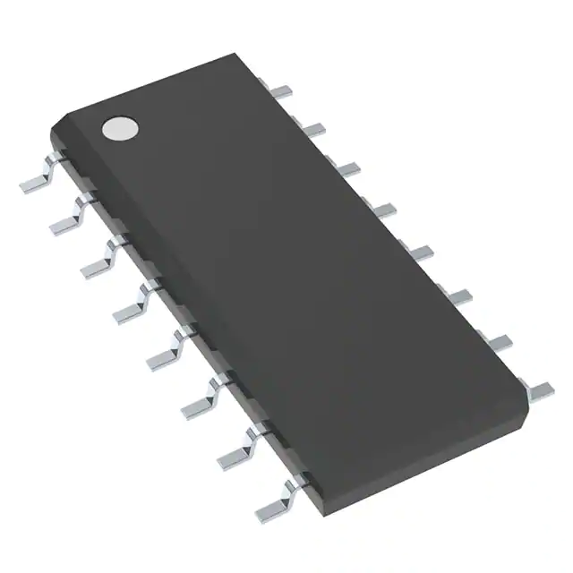
SO14 narrow-body surface-mount package (8.65 × 3.90 × 1.75 mm), RoHS-compliant, with standard JEDEC MS-012AC footprint and thermal pad not electrically connected.
| Pin/Terminal | Circuit Role | Design Meaning |
|---|---|---|
| 1 INV | Inverting input of error amplifier | Accepts resistor-divided output voltage feedback; sinks programmable current from TBO pin when tracking boost is enabled. |
| 2 COMP | Error amplifier output | Drives compensation network; gate drive inhibited below 2.4 V to enable burst-mode at light load. |
| 3 MULT | Mains voltage input to multiplier | Receives rectified AC via divider; provides sinusoidal current reference and RMS sensing for feedforward. |
| 4 CS | PWM comparator input | Senses MOSFET current via sense resistor; 1.7 V threshold triggers saturation protection. |
| 5 VFF | Voltage feedforward input | Connects to RC network for peak-hold; generates DC level equal to MULT peak for 1/V² gain correction. |
| 6 TBO | Tracking boost output | Buffered VFF voltage; sets INV sink current to scale output voltage proportionally with AC input. |
| 7 PFC_OK | Output voltage monitor / disable | Dual-function: OVP (2.5 V trip) and remote ON/OFF (0.23 V shutdown, 0.27 V wake-up). |
| 8 PWM_LATCH | Latched fault signaling output | Asserts high on feedback failure (INV < 1.66 V + PFC_OK > 2.5 V); used to latch off downstream PWM controller. |
| 9 PWM_STOP | Non-latched fault signaling output | Pulled low during RUN-disable or brownout; used to temporarily halt downstream converter without latching. |
| 10 RUN | Remote ON/OFF control input | 0.8 V threshold shutdown (non-latched); tied to VFF for automatic brownout protection. |
| 11 ZCD | Zero-current detection input | Negative edge triggers MOSFET turn-on; enables accurate TM timing and prevents hard switching. |
| 12 GND | Signal and gate driver ground | Common return for analog circuitry and 800 mA sink driver - requires low-inductance layout. |
| 13 GD | Gate driver output | Totem-pole output clamped to ~12 V; drives gate capacitance directly with 600 mA/800 mA peak capability. |
| 14 Vcc | IC supply input | Self-limited to ~15 V; UVLO threshold 10.5 V (on), 9.5 V (off); bypass capacitor recommended. |
Key Features
| Feature | Design Value |
|---|---|
| Tracking Boost Function | Output voltage dynamically scales with AC input via TBO-resistor programming - maintains optimal efficiency across universal mains (85–265 VAC). |
| Bidirectional 1/V² Feedforward | Proprietary squarer-divider circuit corrects loop gain for both line sags and surges - reduces THD by up to 40% vs conventional TM controllers. |
| Latched Feedback Failure Protection | Simultaneous PFC_OK > 2.5 V and INV < 1.66 V triggers irreversible shutdown until Vcc cycle - prevents runaway output during open-loop faults. |
| Inductor Saturation Detection | CS pin monitors MOSFET current; 1.7 V threshold initiates immediate soft-stop - avoids core saturation damage and MOSFET avalanche stress. |
| Interface for Cascaded PWM Controller | Dedicated PWM_STOP and PWM_LATCH outputs enable coordinated shutdown/startup with downstream DC-DC stage - simplifies Blue Angel/EnergyStar compliance. |
Applications
| High-End Desktop PC Power Supply | IEC61000-3-2 Compliant Server PSU |
|---|---|
|
Use Scenario: 500–800 W ATX or EPS12V power supply operating from 85–265 VAC with strict harmonic current limits. IC Role / Device Role / Timing Role: Primary PFC controller regulating 380–400 V DC bus using TM boost topology with ZCD-synchronized MOSFET switching. Use Value: Bidirectional 1/V² feedforward ensures THD < 5% across full load (10–100%) and universal input, meeting Class D limits without additional filtering. |
Use Scenario: Redundant 1+1 or N+1 server power supply requiring high reliability, brownout resilience, and energy-saving light-load behavior. IC Role / Device Role / Timing Role: Master-stage PFC controller coordinating with downstream LLC resonant converter via PWM_STOP/PWM_LATCH signals. Use Value: RUN pin brownout protection disables PFC before DC-DC undervoltage lockout; PWM_STOP enables seamless light-load burst mode per EnergyStar v8.0 requirements. |
| Industrial AC-DC Adapter (>400 W) | Medical-Grade Power Supply Pre-regulator |
|
Use Scenario: 450–600 W industrial adapter powering PLCs, motor drives, or test equipment with wide ambient temperature range (−40 to +85 °C). IC Role / Device Role / Timing Role: Transition-mode PFC controller with TBO-based tracking boost to maintain constant power density across 90–277 VAC inputs. Use Value: 1% reference voltage and −40 to +150 °C junction rating ensure stable 400 V bus regulation under thermal stress, supporting long-term reliability certification. |
Use Scenario: 350–500 W medical power supply requiring reinforced isolation, fault containment, and fail-safe shutdown per IEC 60601-1. IC Role / Device Role / Timing Role: Safety-critical PFC controller implementing latched FFP, OVP, and saturation protection as independent hardware safeguards. Use Value: Dual-level protection (latched FFP + non-latched OVP/brownout) guarantees bus voltage never exceeds 430 V - satisfying creepage/clearance and risk management requirements. |
Equivalent & Alternatives
The following parts are listed as comparable options for similar PFC controller applications.
| Alternative Part | Technical Difference | Application Difference | Selection Advice |
|---|---|---|---|
| UCC28070 | Continuous conduction mode (CCM) controller with average current mode; no ZCD or TM support; higher component count for same power level. | Targeted at >750 W CCM designs where efficiency at full load outweighs light-load penalty; lacks tracking boost and 1/V² feedforward. | Select UCC28070 only when CCM topology is mandated for EMI profile or transformer size constraints - not a drop-in replacement. |
| L6562A | Legacy TM PFC controller; no TBO pin, no latched FFP, no bidirectional feedforward; 2% reference accuracy; lower gate drive (500 mA sink). | Suitable for cost-sensitive <400 W adapters with relaxed THD and safety requirements; cannot meet JEITA-MITI or latest EnergyStar specs. | L6562A may be used for legacy redesigns where BOM cost is prioritized over compliance margin - but requires full revalidation of protection timing. |
Compared with UCC28070 and L6562A, the L6563S uniquely combines transition-mode efficiency, hardware-enforced safety latching, and adaptive feedforward - making it the only choice for new >400 W designs targeting dual-standard compliance and extended input range without design compromises.
Availability
L6563S is available at Aetrix Electronics and suitable for high-end desktop PC power supplies, IEC61000-3-2 compliant server PSUs, and industrial AC-DC adapters requiring stable component supply, long lifecycle assurance, and full regulatory documentation support.
Supply support for L6563S includes scheduled delivery planning, volume procurement assistance, BOM continuity management, traceable sourcing, and lifecycle availability coordination for OEM customers, industrial embedded developers, connected-device designers, and electronics production programs.
Manufacturer
STMicroelectronics is a global semiconductor leader headquartered in Geneva, Switzerland, specializing in power management, analog, microcontrollers, and automotive ICs - with over 40 years of power conversion IP development.
The L6563S belongs to ST's high-performance PFC controller product line, engineered specifically for universal-input, high-power SMPS requiring ultra-low THD, robust fault handling, and seamless integration with downstream DC-DC stages.
FAQ
What is the purpose of the TBO pin on the L6563S?
The TBO (Tracking Boost Output) pin provides a buffered version of the VFF voltage and sinks a programmable current into the INV pin when enabled. This current linearly adjusts the error amplifier's setpoint, causing the regulated output voltage to scale proportionally with the AC input voltage - maintaining optimal boost ratio and efficiency across universal mains ranges (85–265 VAC) without software intervention.
How does the L6563S implement bidirectional 1/V² feedforward?
The L6563S uses an internal squarer-divider circuit that derives a DC voltage from the rectified AC peak (via VFF) and applies it to the multiplier's gain path. Unlike unidirectional feedforward, this architecture dynamically corrects loop gain during both line sags and surges - verified in Figure 36 of the datasheet - resulting in faster transient recovery and up to 40% lower THD compared to standard TM controllers under dynamic line conditions.
Can the L6563S be used in continuous conduction mode (CCM)?
No - the L6563S is exclusively designed for transition-mode (TM) operation. Its ZCD pin, fixed-off-time logic, and current-sense comparator thresholds are optimized for zero-current switching in discontinuous/transition modes. Attempting CCM operation will cause erratic switching, loss of regulation, and potential device damage due to missing slope compensation and incorrect timing control.
What happens during a feedback loop disconnection event?
When PFC_OK exceeds 2.5 V (indicating overvoltage) while INV falls below 1.66 V (indicating open feedback), the L6563S enters latched shutdown: GD stops switching, PWM_LATCH asserts high, and the device remains disabled until Vcc is cycled below 6 V. This hardware-level protection prevents uncontrolled bus voltage rise and satisfies IEC 62368-1 fault containment requirements.
L6563S Specifications
- Product attributes
- Attribute value
- Manufacturer:
- STMicroelectronics
- Series:
- -
- Package/Case:
- 14-SOIC (0.154", 3.90mm Width)
- Packaging:
- Tube
- Product Status:
- Active
- Mode:
- Discontinuous (Transition)
- Frequency - Switching:
- -
- Current - Startup:
- 90 µA
- Voltage - Supply:
- 10.3V ~ 22.5V
- Operating Temperature:
- -40°C ~ 150°C
- Grade:
- -
- Qualification:
- -
- Mounting Type:
- Surface Mount
- Supplier Device Package:
- 14-SO
L6563S FAQ
1.How can I place an order for L6563S through Aetrix?
Please submit a Request for Quotation (RFQ) for L6563S on Aetrix. Our sales agent will provide a competitive quotation and guide you through the order confirmation once you accept the terms.
2.Are the price and stock information for L6563S reliable?
The price and inventory of L6563S are updated periodically and may fluctuate due to market conditions. Stock and pricing data are typically refreshed every 24 hours. Quotation validity for L6563S is usually 5 days.
3.What payment methods are accepted for L6563S?
We accept Wire Transfer, PayPal, Credit Card, Western Union, MoneyGram, and Escrow for L6563S transactions.
Note: Certain payment methods may incur a processing fee.
4.How is shipping managed for L6563S?
L6563S orders can be shipped via leading logistics carriers, including DHL, UPS, FedEx, TNT, or Registered Mail.
Once your L6563S order is processed, you will receive an email with the shipment details and tracking number.
Note: Tracking information may take up to 24 hours to appear. Express delivery typically takes 3–5 business days.
5.How can I obtain technical support or documentation for L6563S?
For technical support, including L6563S datasheets, pinout diagrams, or application guidance, please contact our engineering support team. They can provide detailed documentation and assistance for your L6563S requirements.
6.How does Aetrix verify that L6563S is sourced from the original manufacturer or authorized distributors?
All L6563S products on Aetrix are procured from qualified distributors and authorized channels. Our dedicated quality assurance team conducts strict verification, including traceability checks and, if necessary, third-party testing. This ensures that L6563S meets industry standards.
7.What is the process for return or replacement of L6563S?
All L6563S units undergo pre-shipment inspection (PSI). If there is an issue with L6563S, returns or replacements are accepted under the following conditions:
1.Quantity discrepancies, incorrect items, or visible external defects (such as breakage or corrosion), acknowledged by Aetrix.
2.The issue is reported within 90 days of delivery.
3.The L6563S part is unused and in its original packaging.
Return procedure for L6563S:
1.Submit a request within 90 days.
2.Obtain a Return Material Authorization (RMA) from Aetrix.
L6563S Tags

-
ICE2PCS01GXUMA1
Infineon Technologies

-
NCP1654BD133R2G
onsemi
-
MC33262DR2G
onsemi
-
ICE3PCS03GXUMA1
Infineon Technologies
-
NCP1631DR2G
onsemi

-
L4981BD013TR
STMicroelectronics
-
UCC28070DWR
Texas Instruments

-
UCC28070PWR
Texas Instruments

-
UC3854DWTR
Texas Instruments
-
L4981AD013TR
STMicroelectronics

-
UCC2817D
Texas Instruments
-
UC2854BDWTR
Texas Instruments
Tech Hub

Operational amplifier guide covering op amp basics, feedback, ideal vs real op amps, common configurations, buffer circuits, offset, bias current, gain-bandwidth, slew rate, rail-to-rail limits and sel…

Jumper cables guide covering safe connection order, red and black clamp placement, final ground connection, cable gauge, length, clamp quality, copper vs CCA cables, jump starter comparison and battery…

LDO regulator guide covering low dropout voltage, power dissipation, thermal design, PSRR, output noise, capacitor stability, adjustable LDO circuits, LDO vs buck converter and datasheet selection chec…

Conditional Access Module guide covering CAM meaning, CI/CI+ interface, smart card authorization, DVB security workflow, TV and set-top box compatibility, internal electronics, ESD protection, connecto…

Guide to electronic component obsolescence covering EOL risk, PCN/PDN notices, last-time buy planning, replacement options, form-fit-function validation, counterfeit risk and BOM lifecycle management.

18650 battery guide covering lithium-ion cell basics, 3.6V/3.7V voltage, 4.2V charging, mAh and Wh capacity, protected cells, chargers, BMS, series-parallel packs, holders, welding and sourcing checks.…

Hall effect sensor guide covering working principle, linear and digital sensors, Arduino circuits, current sensing, speed detection, automotive applications, A3144 examples, signal filtering and datash…

Product Change Notification guide for electronic components, covering PCN meaning, PCN vs PDN/EOL, common change types, risk levels, form-fit-function review, engineering validation, BOM control, LTB/L…

A practical guide to blend door actuators, covering HVAC function, symptoms, location, AC and heater issues, reset and calibration, replacement cost, electrical diagnosis, compatibility checks, and rep…

Engineering guide to Raspberry Pi alternatives, covering chip-level differences, Orange Pi, ROCK, Jetson, Banana Pi, NanoPi, Compute Module, Pico, GPIO, camera, HAT compatibility, and replacement risks…


