
 My Inquiry
 My Account


STMicroelectronics L6730
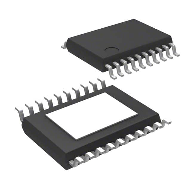
- Part No.:
- L6730
- Manufacturer:
- STMicroelectronics
- Category:
- DC DC Switching Controllers
- Package:
- 20-TSSOP (0.173", 4.40mm Width) Exposed Pad
- Datasheet:
-
 L6730.pdf
- Description:
- IC REG CTRLR BUCK 20TSSOP
- Quantity:
- Payment:

- Shipping:

Inventory:1,142
Please send an inquiry. Send us your inquiry, and we will respond immediately.
Product details
Overview
L6730 from STMicroelectronics is an adjustable synchronous step-down controller for high-current buck converter power stages using external N-channel MOSFETs. The IC supports a 1.8 V to 14 V converter input range, operates from a 4.5 V to 14 V controller supply, regulates output voltage down to 0.6 V, and provides fixed-frequency voltage-mode control for low-voltage distributed power systems.
For engineers reviewing the L6730 datasheet, L6730 pinout, L6730 application, or L6730 equivalent, this controller is most relevant for high-density DC/DC modules, low-voltage distributed power rails, niPOL converters, DDR memory supplies, DDR bus termination rails, and embedded high-current buck regulators requiring programmable 100 kHz to 1 MHz switching frequency, pre-biased startup support, RDS(on)-based current-limit sensing, source / sink selection, and HTSSOP20 exposed-pad assembly.
Technical Context
L6730 drives a synchronous buck stage through HGATE and LGATE outputs and uses fixed-frequency voltage-mode PWM control with external loop compensation. The device supports 0% to 100% duty-cycle operation, minimum on-time below 100 ns, selectable 0.6 V or 1.2 V internal reference, external reference input, and ±0.8% reference accuracy over line voltage and temperature from 0°C to 125°C.
The controller includes predictive anti-cross-conduction gate-drive control, programmable high-side and low-side MOSFET RDS(on) overcurrent protection, selectable UVLO threshold for 5 V or 12 V bus operation, soft-start and inhibit, PGOOD with programmable delay, overvoltage protection with selectable latched or non-latched behavior, thermal shutdown, and synchronization with 180° phase shift for master/slave converter operation.
Key Specifications
| Parameter | Value and Actual Design Meaning |
|---|---|
| Device Type | Adjustable synchronous step-down controller for external-MOSFET buck converter power stages. |
| Converter Input Range | 1.8 V to 14 V, supporting low-voltage distributed DC/DC and high-density point-of-load converter designs. |
| Controller Supply Range | 4.5 V to 14 V VCC operating range for the control IC and driver support circuitry. |
| Output Voltage Range | Adjustable output voltage down to 0.6 V, allowing low-voltage core, DDR, and termination rail generation. |
| Reference Options | Selectable 0.6 V or 1.2 V internal reference plus external input reference for tracking or custom regulation requirements. |
| Reference Accuracy | ±0.8% over line voltage and temperature from 0°C to 125°C, supporting accurate low-voltage power rails. |
| Control Architecture | Fixed-frequency voltage-mode control with synchronous rectification and external compensation through FB and COMP. |
| Switching Frequency | Programmable from 100 kHz to 1 MHz through the OSC pin, balancing inductor size, switching loss, ripple, and transient response. |
| Duty-Cycle Capability | 0% to 100% duty-cycle capability for wide conversion-range behavior across input, output, and load conditions. |
| Minimum On-Time | Below 100 ns, supporting low duty-cycle operation in high step-down ratio applications. |
| Gate Driver Function | High-current embedded drivers for external high-side and low-side N-channel MOSFETs with predictive anti-cross-conduction control. |
| Overcurrent Protection | Programmable high-side and low-side RDS(on)-sense overcurrent protection through OCH, OCL, and PHASE connections. |
| Startup Behavior | Soft-start, inhibit, and pre-biased startup support for rails that may already hold output voltage before converter startup. |
| Synchronization | Master/slave synchronization capability with 180° phase shift for multi-phase or multi-rail converter timing coordination. |
| Protection Functions | Selectable UVLO threshold, PGOOD output with programmable delay, overvoltage protection with latched or non-latched mode, and thermal shutdown. |
| Package | HTSSOP20 exposed-pad package for compact synchronous buck controller layouts. |
Pinout & Package
L6730 is supplied in an HTSSOP20 exposed-pad package. The 20-pin exposed-pad TSSOP format supports compact synchronous buck controller layouts by keeping gate-drive, phase-node, current-limit, oscillator, feedback, soft-start, synchronization, power-good, protection-setting, and supply pins accessible while improving board-level thermal transfer and grounding through the exposed pad.
| Pin / Terminal | Circuit Role | Design Meaning |
|---|---|---|
| Pin 1 - PGOOD | Power-good output. | Provides rail-valid monitoring for system sequencing, reset logic, or supervisory circuits. |
| Pin 2 - DELAY | Power-good delay programming pin. | Connects to the timing network that programs the delay associated with the PGOOD response. |
| Pin 3 - SYNCH | Synchronization pin. | Supports converter synchronization and master/slave timing coordination with 180° phase-shift behavior. |
| Pin 4 - SINK/OVP/UVLO | Source / sink selection, overvoltage mode, and UVLO configuration pin. | Programs post-soft-start source / sink or source-only behavior and selects protection-related operating options. |
| Pin 5 - TMASK | Masking-time setting pin. | Sets masking behavior used by protection and monitoring functions during converter startup and operation. |
| Pin 6 - GND | Signal ground reference. | Provides the small-signal ground reference for control, feedback, oscillator, and protection circuitry. |
| Pin 7 - FB | Feedback input. | Senses the regulated output through the feedback divider and supports voltage regulation and monitoring behavior. |
| Pin 8 - COMP | Error amplifier compensation output. | Connects to the loop compensation network used to stabilize the voltage-mode buck converter. |
| Pin 9 - SS/INH | Soft-start and inhibit control. | An external capacitor programs startup ramp behavior, while the inhibit function disables controller operation when required. |
| Pin 10 - EAREF | Error-amplifier reference input. | Accepts the selected internal or external reference used by the voltage-regulation loop. |
| Pin 11 - OSC | Oscillator frequency setting pin. | Programs switching frequency from 100 kHz to 1 MHz through the external oscillator setting network. |
| Pin 12 - OCL | Low-side overcurrent limit setting pin. | Programs low-side MOSFET RDS(on)-based current-limit behavior through the valley-current sensing path. |
| Pin 13 - OCH | High-side overcurrent limit setting pin. | Programs high-side MOSFET RDS(on)-based current-limit behavior through the peak-current sensing path. |
| Pin 14 - PHASE | Switch-node and high-side driver return. | Connects to the MOSFET switching node and participates in bootstrap driver operation and current sensing. |
| Pin 15 - HGATE | High-side MOSFET gate driver output. | Drives the gate of the external high-side N-channel MOSFET in the synchronous buck power stage. |
| Pin 16 - BOOT | Bootstrap supply pin. | Connects to the bootstrap capacitor used to power the floating high-side gate driver. |
| Pin 17 - PGND | Power ground reference. | Provides the high-current gate-driver ground reference and should be routed close to the low-side MOSFET source path. |
| Pin 18 - LGATE | Low-side MOSFET gate driver output. | Drives the external synchronous rectifier MOSFET gate and supports source / sink current capability in suitable converter modes. |
| Pin 19 - VCCDR | Driver supply output / driver supply rail. | Supplies the internal MOSFET driver section and requires local bypassing for stable gate-drive operation. |
| Pin 20 - VCC | Controller supply input. | Supplies the IC over the 4.5 V to 14 V operating range. |
Key Features
- Adjustable synchronous step-down controller for external N-channel MOSFET buck converter stages.
- 1.8 V to 14 V converter input range and 4.5 V to 14 V controller supply range.
- Output voltage adjustable down to 0.6 V with ±0.8% reference accuracy over line and temperature.
- Selectable 0.6 V or 1.2 V internal reference plus external voltage-reference input.
- Programmable 100 kHz to 1 MHz switching frequency with synchronization and 180° phase-shift capability.
- Minimum on-time below 100 ns and 0% to 100% duty-cycle operation for wide conversion-ratio support.
- Programmable high-side and low-side MOSFET RDS(on) overcurrent sensing without a dedicated sense resistor.
- Pre-biased startup support, selectable source / sink behavior after soft-start, PGOOD delay, OVP, UVLO, and thermal shutdown.
Applications
| High-Density DC/DC Modules | Low-Voltage Distributed Power Rails |
|---|---|
|
Use Scenario: Compact converter modules requiring high-current synchronous buck conversion from intermediate bus rails. IC Role: Voltage-mode PWM controller driving external high-side and low-side N-channel MOSFETs. Use Value: L6730 lets engineers choose MOSFETs, inductor, switching frequency, and compensation to match the required current level, efficiency, ripple, and board area. |
Use Scenario: Distributed point-of-load supplies converting 1.8 V to 14 V input rails into lower core or I/O voltages. IC Role: Adjustable buck controller with 0.6 V minimum output reference and wide duty-cycle range. Use Value: The below-100 ns minimum on-time and programmable frequency support low-voltage rails generated from higher system buses. |
| DDR Memory Supply and Termination | Multi-Rail Synchronized Power Systems |
|
Use Scenario: DDR memory power systems needing controlled startup, source / sink behavior, and accurate low-voltage regulation. IC Role: Synchronous buck controller with selectable reference and source / sink operating behavior after soft-start. Use Value: Output regulation down to 0.6 V, pre-biased startup support, and source / sink selection make the IC useful in DDR rail and termination-related converter designs. |
Use Scenario: Power systems where multiple buck converters must operate with coordinated switching timing. IC Role: PWM controller with synchronization capability and 180° phase-shift support. Use Value: Master/slave synchronization helps reduce input ripple concentration and supports more controlled EMI and transient behavior across multi-rail boards. |
Equivalent & Alternatives
When evaluating L6730 equivalent devices, engineers should compare package, packing format, source / sink behavior, overcurrent response mode, switching-frequency range, reference options, MOSFET gate-drive requirements, UVLO setting, PGOOD delay, pre-biased startup behavior, and whether the existing PCB uses the L6730 HTSSOP20 pinout.
| Alternative Part | Technical Difference | Application Difference | Selection Advice |
|---|---|---|---|
| L6730TR | Same L6730 controller function and HTSSOP20 package, but supplied in tape-and-reel packaging instead of tube packaging. | Useful when the same circuit design is retained but automated SMT assembly requires reel-fed component handling. | Select L6730 for tube-based handling or engineering quantities; select L6730TR when tape-and-reel production logistics are required. |
| L6730B | Same L6730B family concept and HTSSOP20 package, but the B version uses CC/OVP/UVLO behavior for selectable constant-current or hiccup-mode overcurrent response after soft-start. | Better suited when the design requirement is focused on the L6730B overcurrent-response configuration rather than the L6730 source / sink selection behavior. | Compare L6730 and L6730B by multifunction-pin behavior, protection strategy, hardware fault handling, and the existing protection-mode network. |
| L6730BTR | Same L6730B electrical variant as L6730B, but supplied in tape-and-reel packaging. | Used when the B-version protection behavior is required and the manufacturing flow needs reel-fed SMT placement. | Select only after confirming that the L6730B multifunction-pin behavior matches the converter design; it should not be substituted for L6730 without reviewing the protection-mode network. |
Compared with L6730TR, L6730 keeps the same controller architecture, pinout, HTSSOP20 package, and electrical function, with the main difference being tube versus tape-and-reel logistics. L6730 vs L6730B selection depends on whether the converter design needs the L6730 source / sink selection behavior or the L6730B constant-current / hiccup overcurrent-response option.
Quality
L6730 should be sourced as original STMicroelectronics components through traceable and controlled supply channels. Quality verification procedures may include HTSSOP20 exposed-pad package inspection, top-mark validation, tube label review, solderability testing, exposed-pad inspection, VCC and VCCDR continuity checks, HGATE / LGATE driver-function testing, oscillator-frequency verification, PGOOD timing inspection, current-limit threshold review, and incoming inspection according to synchronous buck converter production requirements.
Availability
L6730 is available at Aetrix Electronics and suitable for high-density DC/DC modules, low-voltage distributed power rails, niPOL converters, DDR memory supplies, DDR bus termination rails, and embedded high-current buck regulators requiring stable component supply and repeatable production support.
Supply support may include scheduled delivery planning, volume procurement support, BOM continuity assistance, traceable sourcing management, and long-term availability support for power-supply manufacturers, industrial equipment builders, computing hardware developers, repair groups, contract manufacturers, and legacy product owners using ST synchronous buck controller designs.
For production deployment, confirming the HTSSOP20 exposed-pad footprint, tube handling format, input-voltage range, MOSFET gate-drive requirement, oscillator setting, compensation network, RDS(on) current-limit design, source / sink selection, protection-mode network, thermal requirements, and sourcing continuity helps reduce procurement risk and improve manufacturing stability.
Manufacturer
STMicroelectronics supplies power-management ICs, synchronous buck controllers, converters, microcontrollers, sensors, RF devices, protection products, and discrete semiconductors for industrial, automotive, consumer, communication, and embedded applications. L6730 belongs to ST's power-management controller portfolio for high-current synchronous step-down conversion and low-voltage point-of-load power systems.
FAQ
What is L6730 used for?
L6730 is used to control high-current synchronous buck converters in high-density DC/DC modules, distributed point-of-load supplies, niPOL converters, DDR memory supplies, and DDR bus termination rails. It drives external N-channel MOSFETs and provides programmable frequency, soft-start, overcurrent protection, power-good monitoring, synchronization, and low-voltage output regulation.
What input and output voltage ranges does L6730 support?
L6730 supports a converter input voltage range from 1.8 V to 14 V and a controller supply range from 4.5 V to 14 V. The regulated output voltage can be adjusted down to 0.6 V using the feedback and reference system, making the IC suitable for low-voltage core, memory, and termination rail applications.
How is the switching frequency set on L6730?
L6730 uses the OSC pin to program the switching frequency from 100 kHz to 1 MHz. Frequency selection affects inductor size, switching loss, output ripple, transient response, MOSFET dissipation, and EMI behavior, so the oscillator setting should be chosen together with the external power-stage design.
How does L6730 implement overcurrent protection?
L6730 implements programmable high-side and low-side overcurrent protection using the RDS(on) of the external MOSFETs. OCH sets the high-side peak current limit, OCL sets the low-side current-limit behavior, and PHASE provides the switching-node reference. This avoids a dedicated sense resistor but requires careful MOSFET, layout, and temperature-margin selection.
What package is used by L6730?
L6730 uses an HTSSOP20 exposed-pad package. The package provides 20 pins for feedback, compensation, soft-start, oscillator, synchronization, PGOOD, protection configuration, gate-drive outputs, bootstrap supply, current-limit sensing, and controller supply connections, while the exposed pad improves grounding and board-level thermal behavior.
What is the difference between L6730 and L6730TR?
L6730 and L6730TR use the same controller function, HTSSOP20 package, pinout, and electrical architecture. The difference is packaging logistics: L6730 is supplied in tube packaging, while L6730TR is supplied in tape-and-reel format for automated SMT assembly.
What is the difference between L6730 and L6730B?
L6730 and L6730B are related ST synchronous step-down controller options in the HTSSOP20 package, but the multifunction protection pin differs. L6730 uses SINK/OVP/UVLO behavior for source / sink selection and protection configuration, while L6730B uses CC/OVP/UVLO behavior for selectable constant-current or hiccup overcurrent response after soft-start.
Can L6730 start into a pre-biased output rail?
Yes. L6730 includes pre-biased startup capability, which is useful when the output rail may already hold voltage before the controller starts. This behavior is important in DDR, multi-rail, and redundant power systems where uncontrolled sink current during startup could disturb the existing rail voltage.
L6730 Specifications
- Product attributes
- Attribute value
- Manufacturer:
- STMicroelectronics
- Series:
- -
- Package/Case:
- 20-TSSOP (0.173", 4.40mm Width) Exposed Pad
- Packaging:
- Tube
- Product Status:
- Obsolete
- Output Type:
- Transistor Driver
- Function:
- Step-Down
- Output Configuration:
- Positive
- Topology:
- Buck
- Number of Outputs:
- 1
- Output Phases:
- 1
- Voltage - Supply (Vcc/Vdd):
- 4.5V ~ 14V
- Frequency - Switching:
- 100kHz ~ 1MHz
- Duty Cycle (Max):
- 100%
- Synchronous Rectifier:
- Yes
- Clock Sync:
- Yes
- Serial Interfaces:
- -
- Control Features:
- Enable, Frequency Control, Phase Control, Power Good, Soft Start
- Operating Temperature:
- -40°C ~ 85°C (TA)
- Grade:
- -
- Qualification:
- -
- Mounting Type:
- Surface Mount
- Supplier Device Package:
- 20-HTSSOP
L6730 FAQ
1.How can I place an order for L6730 through Aetrix?
Please submit a Request for Quotation (RFQ) for L6730 on Aetrix. Our sales agent will provide a competitive quotation and guide you through the order confirmation once you accept the terms.
2.Are the price and stock information for L6730 reliable?
The price and inventory of L6730 are updated periodically and may fluctuate due to market conditions. Stock and pricing data are typically refreshed every 24 hours. Quotation validity for L6730 is usually 5 days.
3.What payment methods are accepted for L6730?
We accept Wire Transfer, PayPal, Credit Card, Western Union, MoneyGram, and Escrow for L6730 transactions.
Note: Certain payment methods may incur a processing fee.
4.How is shipping managed for L6730?
L6730 orders can be shipped via leading logistics carriers, including DHL, UPS, FedEx, TNT, or Registered Mail.
Once your L6730 order is processed, you will receive an email with the shipment details and tracking number.
Note: Tracking information may take up to 24 hours to appear. Express delivery typically takes 3–5 business days.
5.How can I obtain technical support or documentation for L6730?
For technical support, including L6730 datasheets, pinout diagrams, or application guidance, please contact our engineering support team. They can provide detailed documentation and assistance for your L6730 requirements.
6.How does Aetrix verify that L6730 is sourced from the original manufacturer or authorized distributors?
All L6730 products on Aetrix are procured from qualified distributors and authorized channels. Our dedicated quality assurance team conducts strict verification, including traceability checks and, if necessary, third-party testing. This ensures that L6730 meets industry standards.
7.What is the process for return or replacement of L6730?
All L6730 units undergo pre-shipment inspection (PSI). If there is an issue with L6730, returns or replacements are accepted under the following conditions:
1.Quantity discrepancies, incorrect items, or visible external defects (such as breakage or corrosion), acknowledged by Aetrix.
2.The issue is reported within 90 days of delivery.
3.The L6730 part is unused and in its original packaging.
Return procedure for L6730:
1.Submit a request within 90 days.
2.Obtain a Return Material Authorization (RMA) from Aetrix.
L6730 Tags

-
UCC28C45DR
Texas Instruments
-
UCC28C40DR
Texas Instruments
-
UCC28C43DR
Texas Instruments

-
ZXSC410E6TA
Diodes Incorporated

-
LM3524DMX/NOPB
Texas Instruments

-
LM3489MMX/NOPB
Texas Instruments
-
MIC2102YML-TR
Microchip Technology

-
LM5148RGYR
Texas Instruments
-
TL598CDR
Texas Instruments

-
LM5155DSSR
Texas Instruments

-
LM25085MYX/NOPB
Texas Instruments
-
UCC2813DTR-0
Texas Instruments
Tech Hub

A practical engineering and sourcing framework covering lifecycle verification, lifetime-buy calculations, replacement qualification, supplier checks and counterfeit-risk controls.

TTL and CMOS logic families differ in thresholds, loading, output drive, power and timing. This engineering guide compares 74HC and 74HCT, calculates noise margins and checks 3.3 V/5 V compatibility.

A practical engineering guide to 3.3V and 5V logic compatibility, input thresholds, resistor dividers, translator ICs, MOSFET level shifting, I2C pull-ups, timing limits and power-sequencing risks.

The 74HC595 uses push-pull logic outputs, while the TPIC6B595 uses 50 V open-drain DMOS sinks for higher-power loads. This guide compares timing, current limits, 3.3 V interfacing, load wiring, thermal…

The 74HC595 converts serial data into eight stable parallel outputs. This guide covers pin functions, shift and storage timing, OE and MR behavior, drive-current limits, cascading, voltage compatibilit…

A technical comparison of level-sensitive latches and edge-triggered flip-flops, covering timing windows, setup and hold limits, master–slave operation, time borrowing, race-through, HDL inference and…

A D latch stores one bit while Enable controls when data can pass. This reference covers gate-level operation, truth tables, transparency, setup and hold timing, LE versus OE, common ICs and practical …

An SR latch stores one bit through cross-coupled feedback. This engineering reference covers NOR and NAND implementations, truth tables, forbidden-state recovery, gated operation, switch debouncing, fa…

Latch circuits retain one bit through feedback. This technical reference covers SR and D latches, truth tables, transparency, timing limits, latch-versus-flip-flop behavior, applications and common log…

An engineering guide to LED driver operation, constant-current and constant-voltage outputs, linear and switching topologies, dimming, IC selection, calculations, replacement compatibility, and fault c…


