
 My Inquiry
 My Account


STMicroelectronics L6740LTR
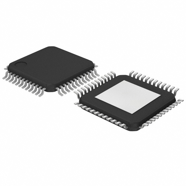
- Part No.:
- L6740LTR
- Manufacturer:
- STMicroelectronics
- Category:
- Power Supply Controllers, Monitors
- Package:
- 48-TQFP Exposed Pad
- Datasheet:
-
 L6740LTR.pdf
- Description:
- IC HYBRID CONTROLLERS 48TQFP
- Quantity:
- Payment:

- Shipping:

Inventory:8,988
Please send an inquiry. Send us your inquiry, and we will respond immediately.
Product details
Overview
L6740LTR from STMicroelectronics is a hybrid 4+1-phase CPU power supply controller for AMD SVID and PVID processors, integrating independent dual-loop control for CPU CORE (2–4 phases) and NB (1 phase), with 150 kHz fixed/adjustable oscillator, PSI_L-driven light-load efficiency optimization, and dual over-current protection (average + per-phase). It supports desktop/server VRM/VRD designs requiring precise voltage positioning and remote sensing.
For engineers reviewing the L6740LTR datasheet, L6740LTR pinout, L6740LTR application, or L6740LTR equivalent, key selection criteria include SVI/PVI protocol compatibility, HTQFP48 thermal performance, dual-plane voltage positioning, LTB Technology™ transient response enhancement, and programmable OVP/PSI_L timing coordination.
Technical Context
The L6740LTR implements a dual-edge asynchronous architecture with LTB Technology™ to minimize output capacitance and improve load-transient response. Its dual control loops operate independently: one for CORE (supporting 2–4 scalable phases via PWM1–PWM4) and one for NB (NB_PWM), each with dedicated current sensing (CS1+/- through CS4+/- and NB_ISEN), error amplifiers (COMP/NB_COMP), and remote sense inputs (VSEN/NB_VSEN, FBG/NB_FBG).
It decodes VID commands in both PVI (parallel DAC-based) and SVI (serial bus) modes, with automatic mode detection via VID1 edge on EN assertion. PSI_L enables phase shedding during low-power states, while OC_AVG/LI provides CORE-section average over-current latching and load-indicator scaling, and OC_PHASE sets per-phase threshold via ROC_TH.
Key Specifications
| Parameter | Value and Actual Design Meaning |
|---|---|
| Oscillator Frequency | Internally fixed at 150 kHz; externally adjustable via ROSC resistor (6.8 kHz/µA gain) for fine-tuning switching speed. |
| CORE Phases | Scalable 2–4 phases (PWM1–PWM4); supports 4+1, 3+1, or 2+1 topologies for flexible high-current CPU rail design. |
| Output Voltage Interface | Hybrid support for AMD PVI (VID0–VID5) and SVI (SVD/SVC/PWROK) protocols with automatic mode detection. |
| Over-Current Protection | Dual-level: average OC (OC_AVG/LI pin, 2.5 V threshold) and per-phase OC (OC_PHASE pin, 1.24 V reference). |
| Voltage Positioning | Programmable droop via DROOP/NB_DROOP pins; offset adjustable via OS/NB_OS (1.24 V internal reference) with external ROS resistors. |
| Remote Sensing | Dual independent remote sense: CORE (VSEN/FBG) and NB (NB_VSEN/NB_FBG), enabling accurate load-point regulation. |
| PSI Management | PSI_L open-drain I/O enables coordinated phase shutdown during CPU low-power states to boost light-load efficiency. |
Pinout & Package
Package: HTQFP48 (7 mm × 7 mm, 0.5 mm pitch), thermally enhanced with exposed pad for improved power dissipation in high-current VRM applications.
| Pin/Terminal | Circuit Role | Design Meaning |
|---|---|---|
| VCC (Pin 1) | Device power supply | 12 V ±15% input; requires 1 µF MLCC to SGND for stable core biasing. |
| SGND (Pin 2) | Signal ground reference | Common reference for all internal analog blocks; must connect to PCB signal ground plane. |
| COMP / NB_COMP (Pins 3 / 34) | Error amplifier output | Drives compensation network (RF-CF) for CORE/NB loop stability; not disableable by grounding. |
| FB / NB_FB (Pins 4 / 33) | Error amplifier inverting input | Connects to VSEN/NB_VSEN via RFB; sinks offset current programmed by OS/NB_OS for voltage positioning. |
| VSEN / NB_VSEN (Pins 6 / 31) | Output voltage monitor | Direct connection to positive load terminal enables OVP/UVP protection and PWRGOOD generation. |
| FBG / NB_FBG (Pins 7 / 30) | Remote ground sense | Connects to negative load terminal to cancel PCB IR drop and ensure accurate regulation at point-of-load. |
| PWM1–PWM4 / NB_PWM (Pins 48,47,46,45 / 44) | Gate drive outputs | Drive external high-side MOSFETs; support interleaved operation for ripple cancellation and thermal spreading. |
| CS1+–CS4+ / NB_ISEN (Pins 13,15,17,19 / 23) | Current sense positive inputs | Connect to phase inductor high-side for accurate per-phase current measurement and balancing. |
Key Features
| Feature | Design Value |
|---|---|
| LTB Technology™ transient response | RLTB–CLTB network detects load steps on CORE rail to accelerate PWM duty-cycle adjustment, reducing required bulk capacitance. |
| Dual-plane voltage positioning | Independent DROOP and NB_DROOP pins enable programmable load-line slope for CORE and NB rails to meet AMD VRM/VRD specifications. |
| Pre-biased startup (LS-Less) | Enables safe start-up into pre-charged output without reverse current flow, critical for hot-swap and multi-rail sequencing. |
| Feedback disconnection protection | Monitors FB/FBG and NB_FB/NB_FBG continuity; disables outputs if sense lines disconnect to prevent unregulated overvoltage. |
| Flexible driver interface | DRV-compatible gate outputs support discrete or integrated drivers (e.g., L6741/L6743), enabling scalable power stage design. |
Applications
| Desktop CPU VRM | Server NB Power Delivery |
|---|---|
Use Scenario: High-density ATX motherboard powering AMD AM2/AM2+ CPUs with dynamic VID scaling. IC Role / Device Role / Timing Role: Primary hybrid controller managing 4-phase CORE and 1-phase NB rails, coordinating PWROK handshake and PSI_L state transitions. Use Value: Enables compliance with AMD VRM 11.x specifications including voltage positioning, phase shedding, and fast transient response under 20 A load steps. | Use Scenario: Dual-rail server motherboard delivering tightly regulated voltage to integrated northbridge logic. IC Role / Device Role / Timing Role: Dedicated NB controller section (NB_PWM, NB_ISEN, NB_VSEN) operates synchronously with CORE but uses independent compensation and protection. Use Value: Maintains NB rail stability during CPU frequency scaling events, preventing timing violations in memory controller and PCIe root complex. |
| Workstation VRD Design | Industrial IPC Power System |
Use Scenario: High-reliability workstation platform supporting multi-core Opteron processors with extended temperature operation. IC Role / Device Role / Timing Role: Hybrid controller executing SVI protocol for dynamic voltage/frequency scaling while maintaining dual remote sensing integrity. Use Value: Achieves <±0.5% output accuracy across –40°C to +85°C via dual remote sense and programmable offset calibration. | Use Scenario: Fanless industrial PC requiring silent, thermally robust CPU power with long-term supply continuity. IC Role / Device Role / Timing Role: Core power manager implementing PSI_L–driven phase shedding and LTB-enhanced transient immunity against EMI-induced load spikes. Use Value: Reduces system power consumption by >35% at 10% load while sustaining <100 µs recovery from 80% load step via LTB Technology™. |
Equivalent & Alternatives
The following parts are listed as comparable options for similar hybrid CPU controller applications.
| Alternative Part | Technical Difference | Application Difference | Selection Advice |
|---|---|---|---|
| ISL6322IRZ | Intel IMVP-6 compliant; single-plane focus (CORE only); no native NB section or SVI support. | Designed for Intel Core 2 platforms; lacks AMD-specific SVI decoding, NB_PWM, and NB_ISEN functionality. | Select only for Intel-based designs requiring IMVP-6 compliance and simpler 1-rail topology. |
| RT8859AZSP | Single-controller dual-output (CORE+NB); supports AMD SVI2 but no PVI mode; integrated MOSFET drivers. | Targeted at modern AM4 platforms; lacks LTB Technology™ and separate OC_AVG/LI reporting capability. | Choose when upgrading to SVI2 and requiring driver integration, but not for legacy PVI or LTB-critical transient performance. |
Compared with ISL6322IRZ and RT8859AZSP, the L6740LTR uniquely delivers dual-mode (PVI/SVI) protocol flexibility, dedicated NB control with full sensing/protection, and LTB Technology™ for superior transient response-making it irreplaceable in legacy AMD desktop/server VRM/VRD designs requiring backward compatibility and thermal headroom.
Availability
L6740LTR is available at Aetrix Electronics and suitable for desktop motherboard VRM, server NB power delivery, and industrial IPC CPU power systems requiring stable component supply, long-lifecycle support, and traceable sourcing.
Supply support for L6740LTR includes scheduled delivery planning, volume procurement assistance, BOM continuity management, traceable sourcing, and lifecycle availability coordination for OEM customers, industrial embedded developers, connected-device designers, and electronics production programs.
Manufacturer
STMicroelectronics is a global semiconductor leader specializing in power management, microcontrollers, and analog ICs, with broad industrial and computing portfolio coverage.
The L6740LTR belongs to ST's CPU power controller product line, engineered specifically for AMD processor platforms requiring hybrid PVI/SVI interface support, dual-rail voltage positioning, and high-efficiency multi-phase regulation.
FAQ
What is the function of the LTB and LTB_GAIN pins?
The LTB pin connects to the CORE output rail via an RLTB–CLTB network to detect rapid load transients; the LTB_GAIN pin sets gain via RLTBGAIN resistor to scale LTB response sensitivity. Together they enable LTB Technology™, which accelerates PWM duty-cycle adjustment before traditional error amplifier feedback reacts-reducing output voltage deviation during fast load steps by up to 40%.
How does the L6740LTR handle pre-biased output conditions during startup?
The L6740LTR implements LS-Less startup: it monitors VSEN at power-on and delays gate drive activation until the output reaches a safe threshold, preventing reverse current flow into a pre-charged rail. This avoids stress on external MOSFETs and eliminates need for external anti-backflow circuitry-critical for hot-swap and multi-rail sequencing in server platforms.
Can the L6740LTR operate in single-plane mode only?
Yes-the L6740LTR supports single-plane operation addressing only the CORE section using parallel DAC codification (PVI mode), disabling NB control entirely. In this configuration, NB_PWM, NB_ISEN, and NB-related pins (NB_VSEN, NB_FB, etc.) are unused, and the device functions as a 2–4 phase VRM controller compliant with legacy AMD PVI specifications.
What protections are implemented for feedback line disconnection?
The L6740LTR continuously monitors continuity between FB–FBG and NB_FB–NB_FBG pairs. If either pair opens, the device immediately disables all PWM outputs and asserts FLT on OSC/FLT pin (pulled high to 3.3 V). Recovery requires cycling VCC or EN-preventing unregulated overvoltage that could damage CPU or NB silicon due to loss of closed-loop control.
L6740LTR Specifications
- Product attributes
- Attribute value
- Manufacturer:
- STMicroelectronics
- Series:
- -
- Package/Case:
- 48-TQFP Exposed Pad
- Packaging:
- Tape & Reel (TR)
- Product Status:
- Obsolete
- Programmable:
- Not Verified
- Applications:
- Hybrid Controllers
- Voltage - Input:
- -
- Voltage - Supply:
- 9V ~ 15V
- Current - Supply:
- 20 mA
- Operating Temperature:
- 0°C ~ 125°C
- Grade:
- -
- Qualification:
- -
- Mounting Type:
- Surface Mount
- Supplier Device Package:
- 48-TQFP-EP (7x7)
L6740LTR FAQ
1.How can I place an order for L6740LTR through Aetrix?
Please submit a Request for Quotation (RFQ) for L6740LTR on Aetrix. Our sales agent will provide a competitive quotation and guide you through the order confirmation once you accept the terms.
2.Are the price and stock information for L6740LTR reliable?
The price and inventory of L6740LTR are updated periodically and may fluctuate due to market conditions. Stock and pricing data are typically refreshed every 24 hours. Quotation validity for L6740LTR is usually 5 days.
3.What payment methods are accepted for L6740LTR?
We accept Wire Transfer, PayPal, Credit Card, Western Union, MoneyGram, and Escrow for L6740LTR transactions.
Note: Certain payment methods may incur a processing fee.
4.How is shipping managed for L6740LTR?
L6740LTR orders can be shipped via leading logistics carriers, including DHL, UPS, FedEx, TNT, or Registered Mail.
Once your L6740LTR order is processed, you will receive an email with the shipment details and tracking number.
Note: Tracking information may take up to 24 hours to appear. Express delivery typically takes 3–5 business days.
5.How can I obtain technical support or documentation for L6740LTR?
For technical support, including L6740LTR datasheets, pinout diagrams, or application guidance, please contact our engineering support team. They can provide detailed documentation and assistance for your L6740LTR requirements.
6.How does Aetrix verify that L6740LTR is sourced from the original manufacturer or authorized distributors?
All L6740LTR products on Aetrix are procured from qualified distributors and authorized channels. Our dedicated quality assurance team conducts strict verification, including traceability checks and, if necessary, third-party testing. This ensures that L6740LTR meets industry standards.
7.What is the process for return or replacement of L6740LTR?
All L6740LTR units undergo pre-shipment inspection (PSI). If there is an issue with L6740LTR, returns or replacements are accepted under the following conditions:
1.Quantity discrepancies, incorrect items, or visible external defects (such as breakage or corrosion), acknowledged by Aetrix.
2.The issue is reported within 90 days of delivery.
3.The L6740LTR part is unused and in its original packaging.
Return procedure for L6740LTR:
1.Submit a request within 90 days.
2.Obtain a Return Material Authorization (RMA) from Aetrix.
L6740LTR Tags

-
UC3845AD8TR
Texas Instruments
-
UC2843AD8TR
Texas Instruments

-
LM3880MFX-1AE/NOPB
Texas Instruments
-
LM3880MFX-1AA/NOPB
Texas Instruments

-
INA234AIYBJR
Texas Instruments

-
INA700AYWFR
Texas Instruments
-
LM3880MF-1AE/NOPB
Texas Instruments
-
LM3880MF-1AA/NOPB
Texas Instruments

-
LM3881MM/NOPB
Texas Instruments
-
UCC2802DTR
Texas Instruments

-
NCP4305DMTTWG
onsemi

-
INA237AIDGSR
Texas Instruments
Tech Hub

A practical engineering and sourcing framework covering lifecycle verification, lifetime-buy calculations, replacement qualification, supplier checks and counterfeit-risk controls.

TTL and CMOS logic families differ in thresholds, loading, output drive, power and timing. This engineering guide compares 74HC and 74HCT, calculates noise margins and checks 3.3 V/5 V compatibility.

A practical engineering guide to 3.3V and 5V logic compatibility, input thresholds, resistor dividers, translator ICs, MOSFET level shifting, I2C pull-ups, timing limits and power-sequencing risks.

The 74HC595 uses push-pull logic outputs, while the TPIC6B595 uses 50 V open-drain DMOS sinks for higher-power loads. This guide compares timing, current limits, 3.3 V interfacing, load wiring, thermal…

The 74HC595 converts serial data into eight stable parallel outputs. This guide covers pin functions, shift and storage timing, OE and MR behavior, drive-current limits, cascading, voltage compatibilit…

A technical comparison of level-sensitive latches and edge-triggered flip-flops, covering timing windows, setup and hold limits, master–slave operation, time borrowing, race-through, HDL inference and…

A D latch stores one bit while Enable controls when data can pass. This reference covers gate-level operation, truth tables, transparency, setup and hold timing, LE versus OE, common ICs and practical …

An SR latch stores one bit through cross-coupled feedback. This engineering reference covers NOR and NAND implementations, truth tables, forbidden-state recovery, gated operation, switch debouncing, fa…

Latch circuits retain one bit through feedback. This technical reference covers SR and D latches, truth tables, transparency, timing limits, latch-versus-flip-flop behavior, applications and common log…

An engineering guide to LED driver operation, constant-current and constant-voltage outputs, linear and switching topologies, dimming, IC selection, calculations, replacement compatibility, and fault c…


