
 My Inquiry
 My Account


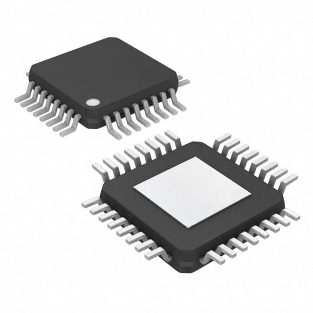
STMicroelectronics L9663
- Part No.:
- L9663
- Manufacturer:
- STMicroelectronics
- Category:
- Specialized
- Package:
- 32-TQFP Exposed Pad
- Datasheet:
-
 L9663.pdf
- Description:
- IC INTERFACE SPECIALIZED 32TQFP
- Quantity:
- Payment:

- Shipping:

Inventory:4,540
Please send an inquiry. Send us your inquiry, and we will respond immediately.
Product details
Overview
L9663 from STMicroelectronics is an AEC-Q100 qualified dual-channel PSI5 transceiver IC for automotive sensor communication, supporting both PSI5 v1.3 and v2.x standards. It delivers Manchester-coded digital data at 125 kbps (with optional 83.3 kbps and 189 kbps), features integrated FLL-based timing control, 32-bit SPI interface with address multiplexing, and operates from 4.8 V to 35 V across –40°C to +140°C ambient. It powers and communicates with PSI5 sensors over a shared line in synchronous or asynchronous bus modes.
For engineers reviewing the L9663 datasheet, L9663 pinout, L9663 application, or L9663 equivalent, this device is selected for ECU-level sensor aggregation in safety-critical automotive systems requiring high EMC robustness, reverse voltage protection, short-to-ground tolerance (±1.5 V ground shift), and diagnostic coverage including VAS/PSIx voltage monitoring, sync pulse amplitude checks, and sensor data consistency validation.
Technical Context
The L9663 implements two independent PSI5 transceiver channels-each with dedicated bootstrap circuits for synchronous pulse generation (VSYNCx), integrated charge pump pre-regulation for VAS, and FLL-based clock recovery ensuring <±0.5% timing accuracy under varying load and temperature. Its receiver includes digital sampling, Manchester decoding with mark-space error correction, and automatic storage of sensor initialization data.
It supports two system architectures: Mode 1 (full on-chip decoding and buffering into internal RAM, SPI-readable via 32-bit interface) and Mode 2 (raw Manchester output to external µC with dedicated PSI5 decoder). Diagnostics cover voltage monitoring (VAS, VSYNCx, PSIx), short-circuit detection, reverse voltage protection, and cross-coupling tests-all compliant with ISO 26262 ASIL-B ready functional safety requirements.
Key Specifications
| Parameter | Value and Actual Design Meaning |
|---|---|
| Data rate | 125 kbps nominal (also supports 83.3 kbps and 189 kbps); enables real-time transmission of multi-sensor data within tight automotive timing budgets. |
| Supply range (VB) | 4.8 V to 35 V; accommodates cold-crank (4.8 V) and load-dump (35 V) conditions without external protection circuitry. |
| Operating temp | –40°C to +140°C ambient; validated for engine bay and transmission ECU placement per AEC-Q100 Grade 0. |
| SPI interface | 32-bit with address multiplexing; reduces MCU GPIO count and simplifies register access in multi-device configurations. |
| VAS pre-regulator | Integrated charge pump + external FET drive; delivers stable 5.3 V or 7.6 V to sensors even during low VB input (e.g., battery sag). |
| FLL accuracy | ±0.5% frequency lock; ensures reliable Manchester decoding without external crystal, reducing BOM cost and board space. |
| Ground shift tolerance | ±1.5 V between ECU and sensor ground; mitigates noise-induced communication errors in distributed chassis wiring. |
Pinout & Package
Available in two RoHS-compliant packages: VFQFPN28 (5 × 5 × 1.0 mm, exposed pad up) and TQFP32EP (7 × 7 × 1.0 mm, exposed pad down). Both support thermal dissipation required for continuous operation at 140°C ambient.
| Pin/Terminal | Circuit Role | Design Meaning |
|---|---|---|
| PSI1 / PSI2 | Bi-directional PSI5 data/power line | Carries modulated current signal and sensor supply voltage (VAS) on same wire; supports point-to-point or bussed topology. |
| VAS | Pre-regulated sensor supply input | Accepts externally regulated 5.3 V or 7.6 V; powers sensors and supplies internal analog blocks for channel 1 & 2. |
| BH1 / BH2, BL1 / BL2 | Bootstrap capacitor terminals | Enable high-voltage synchronous pulse generation (up to 16.5 V) for PSI5 v2.x sync commands without external boost converters. |
| DOUT1 / DOUT2 | Digital output / interrupt | Configurable as Manchester-decoded data output (Mode 1) or raw Manchester stream (Mode 2); doubles as interrupt flag for frame completion/error. |
| SYNC1 / SYNC2 | Sync pulse trigger input | Accepts external sync command from MCU or timer; initiates synchronous sensor readout with precise timing alignment. |
| VDD | Digital I/O supply | Selects 3.3 V or 5 V logic level for SPI and DOUT pins; decouples digital noise from analog sensor interface domain. |
Key Features
| Feature | Design Value |
|---|---|
| Dual independent PSI5 channels | Enables concurrent communication with two sensor clusters (e.g., front/rear axle wheel speed + pressure), eliminating need for multiple ICs. |
| Integrated FLL timing module | Replaces external crystal oscillator; achieves ±0.5% clock stability across voltage/temperature, reducing component count and layout complexity. |
| On-chip Manchester decoder with error correction | Corrects mark/space violations in received frames; eliminates need for software-based decoding in Mode 1, lowering MCU processing load. |
| Comprehensive diagnostics suite | Covers VAS/PSIx under/over-voltage, sync pulse amplitude, buffer empty status, DOUT path integrity, and cross-coupling-enabling ASIL-B compliance. |
| Reverse voltage & short-to-ground protection | Withstands –18 V reverse battery connection and ±1.5 V ground offset; prevents latch-up and communication failure in harsh vehicle environments. |
Applications
| Wheel Speed Sensing | Engine Crankshaft Position |
|---|---|
|
Use Scenario: Real-time measurement of rotational speed and position from passive/active magnetic sensors mounted near wheel hubs or crankshafts. IC Role / Device Role / Timing Role: PSI5 transceiver aggregates signals from up to two sensor pairs, performs Manchester decoding, and delivers time-stamped data via SPI to ECU microcontroller. Use Value: Enables deterministic latency (<50 µs frame processing) and fault detection (e.g., open-circuit, shorted sensor) critical for ABS and engine control algorithms. |
Use Scenario: High-precision angular position tracking during engine start-up and idle, where signal integrity degrades due to low RPM and EMI. IC Role / Device Role / Timing Role: Provides synchronized pulse generation (VSYNCx) and robust Manchester decoding under ±1.5 V ground shift and 35 V load-dump conditions. Use Value: Ensures reliable ignition timing and fuel injection sequencing even during cranking, meeting ASIL-B diagnostic coverage targets. |
| Air Suspension Height Sensors | Brake Pressure Monitoring |
|
Use Scenario: Continuous monitoring of vehicle ride height using multiple inductive or Hall-effect PSI5 sensors across four corners. IC Role / Device Role / Timing Role: Manages bussed-mode PSI5 communication, buffers sensor initialization data automatically, and reports faults via SPI-interrupt-driven polling. Use Value: Reduces ECU firmware overhead by offloading sensor configuration storage and error classification, enabling faster system response to height changes. |
Use Scenario: Redundant brake fluid pressure sensing in electro-hydraulic brake (EHB) systems requiring dual-channel fault-tolerant data acquisition. IC Role / Device Role / Timing Role: Operates two isolated PSI5 channels with independent diagnostics (VAS monitoring, sync amplitude check) to detect sensor or wiring faults before actuation. Use Value: Supports dual-lockstep sensor reading and cross-validation, fulfilling ISO 26262 requirement for redundant pressure feedback in ADAS braking functions. |
Equivalent & Alternatives
The following parts are listed as comparable options for similar PSI5 transceiver applications.
| Alternative Part | Technical Difference | Application Difference | Selection Advice |
|---|---|---|---|
| NXP MC33664 | Single-channel PSI5 transceiver; no integrated FLL-requires external 1–5 MHz clock; lower max data rate (125 kbps only, no 189 kbps option). | Lacks dual-channel capability and synchronous pulse generation for v2.x; suitable for simpler single-sensor nodes, not ECU-level aggregation. | Select when cost-sensitive single-sensor interface is sufficient and external clock sourcing is acceptable. |
| Infineon TLE493D-W2B6 | Integrated 3D magnetic sensor with embedded PSI5 transmitter only-not a transceiver; no receiver, no SPI, no VAS regulation. | Functions as sensor endpoint only; cannot replace L9663 in ECU-side role; requires companion receiver IC for full PSI5 link. | Use only as sensor-side component; not a functional substitute for L9663 in ECU designs. |
Compared with MC33664 and TLE493D-W2B6, the L9663 uniquely combines dual-channel transceiver functionality, integrated FLL timing, VAS pre-regulation, and comprehensive diagnostics-making it the only solution capable of standalone ECU-level PSI5 sensor hub implementation with ASIL-B readiness.
Availability
L9663 is available at Aetrix Electronics and suitable for wheel speed sensing, engine position tracking, air suspension control, and brake pressure monitoring requiring stable component supply across automotive production lifecycles.
Supply support for L9663 includes scheduled delivery planning, volume procurement assistance, BOM continuity management, traceable sourcing, and lifecycle availability coordination for OEM customers, industrial embedded developers, connected-device designers, and electronics production programs.
Manufacturer
STMicroelectronics is a global semiconductor leader specializing in automotive, industrial, and power management solutions, with broad portfolio of AEC-Q100 qualified products and functional safety certifications.
The L9663 belongs to ST's automotive interface IC product line, engineered specifically for robust, high-integrity sensor communication in ECU applications demanding PSI5 v1.3/v2.x compliance, wide supply range, and integrated diagnostics.
FAQ
What are the supported PSI5 protocol versions and key compatibility constraints?
The L9663 supports both PSI5 v1.3 and v2.x standards, including synchronous and asynchronous modes, variable data word lengths (8–28 bits), and bussed or point-to-point topologies. Key constraints include mandatory use of Mode 1 for v2.x sync pulse generation and separate VSYNCx voltage requirements (≥11 V) during sync pulses-details are specified in Sections 1.2 and 3.5 of DS11401 Rev 7.
How does the integrated FLL improve timing accuracy compared to crystal-based alternatives?
The FLL locks to the incoming Manchester-encoded signal's edge transitions, achieving ±0.5% frequency accuracy across –40°C to +140°C and 4.8–35 V supply range-without external crystal or trimming. This eliminates crystal cost, board space, and aging drift, while maintaining decoding reliability under voltage transients and thermal stress where crystal oscillators may fail to start or jitter.
Can the L9663 operate with only asynchronous PSI5 communication, and what supply rails are required?
Yes-the L9663 fully supports asynchronous mode using only the VAS supply (5.3 V or 7.6 V) for sensor power and interface operation; VSYNCx generation and bootstrap circuitry remain inactive. VB (4.8–35 V) and VDD (3.3/5 V) must still be powered for internal logic and SPI/DOUT operation, but no synchronous pulse infrastructure is needed.
What diagnostic capabilities are implemented for sensor line fault detection?
The L9663 provides six dedicated diagnostics: PSIx output under-voltage detection (tUV = 1.2 µs), PSIx reverse voltage monitoring (–18 V tolerance), VAS under/over-voltage lockout, synchronous pulse amplitude verification, buffer empty status flag, and cross-coupling test between channels-each with configurable interrupt reporting via DOUT1/DOUT2 pins per Section 3.7 and Table 7 of the datasheet.
L9663 Specifications
- Product attributes
- Attribute value
- Manufacturer:
- STMicroelectronics
- Series:
- -
- Package/Case:
- 32-TQFP Exposed Pad
- Packaging:
- Tray
- Product Status:
- Active
- Applications:
- -
- Interface:
- SPI
- Voltage - Supply:
- 4.8V ~ 35V
- Supplier Device Package:
- 32-TQFP (7x7)
- Grade:
- Automotive
- Qualification:
- AEC-Q100
- Mounting Type:
- Surface Mount
L9663 FAQ
1.How can I place an order for L9663 through Aetrix?
Please submit a Request for Quotation (RFQ) for L9663 on Aetrix. Our sales agent will provide a competitive quotation and guide you through the order confirmation once you accept the terms.
2.Are the price and stock information for L9663 reliable?
The price and inventory of L9663 are updated periodically and may fluctuate due to market conditions. Stock and pricing data are typically refreshed every 24 hours. Quotation validity for L9663 is usually 5 days.
3.What payment methods are accepted for L9663?
We accept Wire Transfer, PayPal, Credit Card, Western Union, MoneyGram, and Escrow for L9663 transactions.
Note: Certain payment methods may incur a processing fee.
4.How is shipping managed for L9663?
L9663 orders can be shipped via leading logistics carriers, including DHL, UPS, FedEx, TNT, or Registered Mail.
Once your L9663 order is processed, you will receive an email with the shipment details and tracking number.
Note: Tracking information may take up to 24 hours to appear. Express delivery typically takes 3–5 business days.
5.How can I obtain technical support or documentation for L9663?
For technical support, including L9663 datasheets, pinout diagrams, or application guidance, please contact our engineering support team. They can provide detailed documentation and assistance for your L9663 requirements.
6.How does Aetrix verify that L9663 is sourced from the original manufacturer or authorized distributors?
All L9663 products on Aetrix are procured from qualified distributors and authorized channels. Our dedicated quality assurance team conducts strict verification, including traceability checks and, if necessary, third-party testing. This ensures that L9663 meets industry standards.
7.What is the process for return or replacement of L9663?
All L9663 units undergo pre-shipment inspection (PSI). If there is an issue with L9663, returns or replacements are accepted under the following conditions:
1.Quantity discrepancies, incorrect items, or visible external defects (such as breakage or corrosion), acknowledged by Aetrix.
2.The issue is reported within 90 days of delivery.
3.The L9663 part is unused and in its original packaging.
Return procedure for L9663:
1.Submit a request within 90 days.
2.Obtain a Return Material Authorization (RMA) from Aetrix.
L9663 Tags

-
NVT4857UKAZ
NXP Semiconductors

-
TCA8418RTWR
Texas Instruments

-
PCA9546APWR
Texas Instruments

-
MD0100N8-G
Microchip Technology

-
PCA9548APW,118
NXP Semiconductors

-
PCA9540BDP,118
NXP Semiconductors

-
PCA9548APWR
Texas Instruments

-
PCA9546APW,118
NXP Semiconductors

-
PTN3360DBS,518
NXP Semiconductors

-
PCA9546ABS,118
NXP Semiconductors

-
PCA9518PWR
Texas Instruments

-
PCA9545APW,118
NXP Semiconductors
Tech Hub

A practical engineering guide to 3.3V and 5V logic compatibility, input thresholds, resistor dividers, translator ICs, MOSFET level shifting, I2C pull-ups, timing limits and power-sequencing risks.

The 74HC595 uses push-pull logic outputs, while the TPIC6B595 uses 50 V open-drain DMOS sinks for higher-power loads. This guide compares timing, current limits, 3.3 V interfacing, load wiring, thermal…

The 74HC595 converts serial data into eight stable parallel outputs. This guide covers pin functions, shift and storage timing, OE and MR behavior, drive-current limits, cascading, voltage compatibilit…

A technical comparison of level-sensitive latches and edge-triggered flip-flops, covering timing windows, setup and hold limits, master–slave operation, time borrowing, race-through, HDL inference and…

A D latch stores one bit while Enable controls when data can pass. This reference covers gate-level operation, truth tables, transparency, setup and hold timing, LE versus OE, common ICs and practical …

An SR latch stores one bit through cross-coupled feedback. This engineering reference covers NOR and NAND implementations, truth tables, forbidden-state recovery, gated operation, switch debouncing, fa…

Latch circuits retain one bit through feedback. This technical reference covers SR and D latches, truth tables, transparency, timing limits, latch-versus-flip-flop behavior, applications and common log…

An engineering guide to LED driver operation, constant-current and constant-voltage outputs, linear and switching topologies, dimming, IC selection, calculations, replacement compatibility, and fault c…

Operational amplifier guide covering op amp basics, feedback, ideal vs real op amps, common configurations, buffer circuits, offset, bias current, gain-bandwidth, slew rate, rail-to-rail limits and sel…

Jumper cables guide covering safe connection order, red and black clamp placement, final ground connection, cable gauge, length, clamp quality, copper vs CCA cables, jump starter comparison and battery…


