
 My Inquiry
 My Account


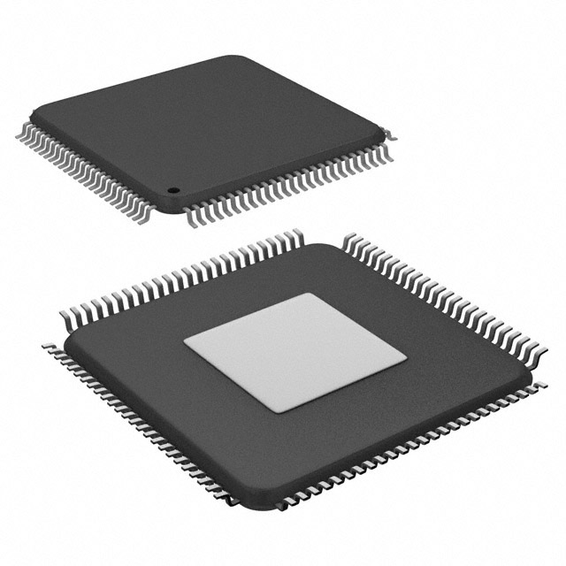
STMicroelectronics L9679PTR
- Part No.:
- L9679PTR
- Manufacturer:
- STMicroelectronics
- Category:
- Specialized
- Package:
- 100-TQFP Exposed Pad
- Datasheet:
-
 L9679PTR.pdf
- Description:
- IC INTERFACE SPECIALIZED 100TQFP
- Quantity:
- Payment:

- Shipping:

Inventory:3,676
Please send an inquiry. Send us your inquiry, and we will respond immediately.
Product details
Overview
L9679PTR from STMicroelectronics is an AEC-Q100 qualified automotive airbag system IC integrating eight-channel squib/pyroswitch drivers, dual boost regulators (ERBOOST at 23 V/33 V and SYNCBOOST at 12 V/14.75 V), three buck regulators (SATBUCK at 7.2 V/9 V, VCC at 3.3 V/5.0 V, VSF for safing switch), energy reserve crossover switch (3 Ω, 912 mA), PSI-5 satellite sensor interface, and 32-bit SPI communications - deployed in mid/high-end airbag control units for passenger and driver-side deployment.
For engineers reviewing the L9679PTR datasheet, L9679PTR pinout, L9679PTR application, or L9679PTR equivalent, this device serves as a fully integrated airbag safety SoC with configurable deployment profiles, real-time squib diagnostics (Rmeasure, STB, STG, leakage), temporal + algorithmic watchdogs, and user-customizable safing logic - critical for ISO 26262 ASIL-B compliant systems requiring deterministic arming/deployment behavior and end-of-life disposal support.
Technical Context
The L9679PTR implements a multi-regulator power architecture: ERBOOST (1.882 MHz, 23/33 V ±5%) charges the energy reserve capacitor while performing ESR/capacitance diagnostics; SYNCBOOST (1.882 MHz, 12/14.75 V) powers PSI-5 SYNC pulses; SATBUCK (1.882 MHz, 7.2/9 V ±4%) supplies remote sensors; and VCC (1.882 MHz, 3.3/5.0 V ±3%) powers the internal MCU domain. All switching regulators share the same oscillator frequency for synchronized operation and EMI control.
Its safety-critical signal chain includes eight independent HSD/LSD deployment drivers with current monitoring, Rmeasure, STB/STG diagnostics, and FET integrity tests; two PSI-5 channels supporting satellite sensors with LCID/CRC data integrity; nine DC sensor inputs (hall/resistive/switch); and three configurable GPOs with 0–100% PWM control - all governed by dual watchdogs (WD1 temporal, WD2 algorithmic) and user-defined safing logic with disarm signaling for passenger airbags.
Key Specifications
| Parameter | Value and Actual Design Meaning |
|---|---|
| Operating voltage | 5.5 V min at battery pin - ensures reliable startup during cranking transients in 12 V automotive systems. |
| Deployment drivers | 8-channel HSD/LSD, 25 V max deployment voltage - supports dual-stage squibs and pyro fuses across front/side/curtain modules. |
| ERBOOST output | 23 V or 33 V ±5%, 55 mA max load - provides configurable energy reserve for guaranteed deployment under low-battery conditions. |
| SYNCBOOST output | 12 V or 14.75 V, 1.882 MHz - supplies precise SYNC pulse to PSI-5 satellite sensors for time-synchronized data acquisition. |
| SATBUCK output | 7.2 V or 9 V ±4%, 1.882 MHz - powers remote acceleration/rotation sensors with tight regulation for analog signal fidelity. |
| VCC output | 3.3 V or 5.0 V ±3%, 1.882 MHz - delivers stable core voltage for internal logic and SPI interface with low noise. |
| Temperature range | −40 °C to +95 °C - validated for under-hood and dashboard mounting in production vehicles. |
| Package | TQFP100 exposed pad down (14 × 14 × 1.0 mm) - enables thermal dissipation for high-current deployment drivers and regulator ICs. |
Pinout & Package
TQFP100 exposed pad down (14 × 14 × 1.0 mm) package with thermal pad on underside for enhanced heat transfer from high-power deployment drivers and regulators. Pin count: 100 leads, 0.5 mm pitch, RoHS-compliant, AEC-Q100 qualified.
| Pin/Terminal | Circuit Role | Design Meaning |
|---|---|---|
| VBAT | Battery supply input | Primary 12 V system connection; minimum 5.5 V required for operation - feeds all internal regulators and monitors for undervoltage shutdown. |
| ERBOOST_OUT | Energy reserve boost output | Switched node for external inductor; connects to energy reserve capacitor bank - enables deployment even after main battery disconnect. |
| SYNCBOOST_OUT | PSI-5 SYNC boost output | Drives PSI-5 bus clock line; voltage programmable to 12 V or 14.75 V - ensures robust synchronization with satellite sensors over long harnesses. |
| SATBUCK_OUT | Remote sensor buck output | Regulated 7.2 V or 9 V supply for PSI-5 satellites or accelerometers - reduces external component count and improves sensor SNR. |
| VCC_OUT | MCU domain buck output | Configurable 3.3 V/5.0 V rail powering internal digital logic, SPI controller, and safing engine - supports mixed-voltage system integration. |
| COVRACT | Energy reserve crossover switch control | Active-high enable for integrated 3 Ω, 912 mA switch - connects ER capacitor to deployment drivers only during arming sequence. |
| DEPx_H / DEPx_L | Deployment driver high/low side outputs | Eight pairs (DEP1–DEP8) driving squib/pyroswitch loads - each pair supports independent current monitoring and open/short diagnostics. |
| PSI5_CHx | PSI-5 channel interface | Two differential channels (CH1/CH2) supporting up to 8 satellite sensors via daisy-chain - includes built-in CRC and LCID validation per frame. |
| GPOx | General purpose output | Three configurable outputs (HSD/LSD/PWM) with 0–100% duty cycle control - used for status indication, external relay control, or secondary actuation. |
| SPI_MOSI/MISO/SCLK/CS | 32-bit SPI interface | Full-duplex serial interface operating up to 10 MHz - enables configuration, real-time status readback, and diagnostic register access. |
Key Features
| Feature | Design Value |
|---|---|
| Integrated energy reserve crossover switch | 3 Ω RDS(on), 912 mA max continuous current - eliminates need for external MOSFET and gate driver in ER path, reducing BOM and layout area. |
| Squib/pyroswitch diagnostics | Rmeasure, STB, STG, leakage, and FET integrity tests - enables pre-deployment verification of squib continuity, insulation resistance, and driver health per ISO 21448 SOTIF. |
| User-customizable safing logic | Configurable thresholds, timing windows, and arming matrix per loop - supports OEM-specific crash discrimination algorithms without firmware update. |
| End-of-life disposal interface | Dedicated hardware pin and SPI command for safe discharge and disable - meets regulatory requirements for airbag retirement and recycling compliance. |
| Temporal + algorithmic watchdogs | WD1 (timer-based reset) and WD2 (data-pattern validation) - provides layered fault detection covering both timing faults and corrupted communication/data paths. |
| PSI-5 satellite sensor interface | Two channels, daisy-chain capable, LCID/CRC protected - enables scalable sensor fusion (accelerometers, gyroscopes, seat occupancy) with minimal wiring and EMI resilience. |
Applications
| Frontal Collision Detection | Side-Impact Occupancy Sensing |
|---|---|
|
Use Scenario: Detects rapid deceleration during frontal crash using integrated accelerometers and PSI-5 satellite sensors. IC Role / Device Role / Timing Role: Central airbag controller executing arming logic, deploying driver/front passenger squibs within ≤30 ms of crash detection. Use Value: Configurable deployment profiles and real-time squib diagnostics ensure single/dual-stage firing matches crash severity - reducing injury risk and false deployments. |
Use Scenario: Monitors seat position, weight, and door intrusion signals to determine occupant presence and optimal airbag staging. IC Role / Device Role / Timing Role: Safing engine processes DC sensor inputs (resistive/hall) and PSI-5 seatbelt tension data to inhibit passenger airbag when empty or child seat detected. Use Value: Specific disarm signal and passenger inhibit thresholds prevent hazardous deployments - meeting FMVSS 208 and Euro NCAP requirements. |
| Pyro Fuse Cut-off System | Multi-Zone Curtain Airbag Control |
|
Use Scenario: Manages pyro-based battery isolation in EVs after crash detection to prevent thermal runaway propagation. IC Role / Device Role / Timing Role: Deployment driver activates pyro fuse via dedicated high-current channel with post-fire continuity verification. Use Value: Integrated Rmeasure and leakage diagnostics confirm successful cut-off and detect latent faults - enabling fail-safe HV system shutdown. |
Use Scenario: Coordinates sequential deployment of roof-rail curtain airbags across driver, passenger, and rear seats based on impact location and severity. IC Role / Device Role / Timing Role: Eight-channel deployment drivers fire multiple squibs with staggered timing controlled via SPI registers and safing state machine. Use Value: Independent current monitoring per channel verifies each curtain segment's deployment integrity - ensuring full coverage without blind zones. |
Equivalent & Alternatives
The following parts are listed as comparable options for similar airbag system controller applications.
| Alternative Part | Technical Difference | Application Difference | Selection Advice |
|---|---|---|---|
| NXP MC33816 | 6-channel deployment drivers; no integrated ERBOOST or SYNCBOOST - requires external boost converters for energy reserve and PSI-5 SYNC. | Limited to lower-tier airbag systems without dual-stage squib support or advanced diagnostics like STG/leakage testing. | Select when cost-sensitive designs accept external regulator BOM and reduced diagnostic depth. |
| Renesas RAA271050 | Single buck regulator (5 V only); no PSI-5 interface - relies on external transceivers for satellite sensor communication. | Suitable for legacy CAN-based airbag ECUs; lacks native support for modern PSI-5 sensor networks and multi-rail power management. | Choose for CAN-only architectures where PSI-5 scalability and integrated power tree are not required. |
Compared with MC33816 and RAA271050, the L9679PTR delivers higher integration (dual boost + triple buck + 8-channel drivers + PSI-5), deeper diagnostics (STG, leakage, FET test), and OEM-customizable safing - making it optimal for ASIL-B mid/high-end platforms demanding functional safety, sensor scalability, and field-proven reliability.
Availability
L9679PTR is available at Aetrix Electronics and suitable for automotive airbag control units, pyro fuse cut-off systems, and multi-zone curtain airbag modules requiring stable component supply, AEC-Q100 qualification, and long-term lifecycle support through June 2026.
Supply support for L9679PTR includes scheduled delivery planning, volume procurement assistance, BOM continuity management, traceable sourcing, and lifecycle availability coordination for OEM customers, industrial embedded developers, connected-device designers, and electronics production programs.
Manufacturer
STMicroelectronics is a global semiconductor leader specializing in automotive, industrial, and power management ICs, with extensive expertise in functional safety and AEC-Q100 qualified products.
The L9679PTR belongs to ST's automotive safety microcontroller and ASSP portfolio, designed specifically for ISO 26262 ASIL-B airbag control units requiring integrated power management, multi-sensor interfaces, and deterministic deployment control.
FAQ
What is the maximum continuous current rating of the integrated energy reserve crossover switch?
The L9679PTR's integrated energy reserve crossover switch supports 912 mA maximum continuous current with 3 Ω typical RDS(on). This rating is validated across the full −40 °C to +95 °C operating temperature range and enables direct connection to standard 1000 µF–2200 µF energy reserve capacitors without external components.
How does the L9679PTR perform squib resistance measurement (Rmeasure)?
Rmeasure is executed using a precision current source and ADC path internal to the L9679PTR. It applies a known current (typically 10 mA) across the squib loop, measures resulting voltage drop, and calculates resistance - reporting values in dedicated SPI registers (DCMTSxy). The measurement supports ranges from 0.5 Ω to 10 Ω with ±0.1 Ω accuracy.
Can the PSI-5 interface operate with non-ST satellite sensors?
Yes - the L9679PTR's PSI-5 interface complies with ISO 17987-2/3 and supports interoperability with any PSI-5-compliant satellite sensor (e.g., Analog Devices ADXL316-based modules, NXP FXLS8471Q). It handles variable frame lengths, LCID addressing, and CRC-8 validation independently of vendor-specific extensions.
What safety certifications does the L9679PTR hold beyond AEC-Q100?
In addition to AEC-Q100 Grade 2 qualification (−40 °C to +105 °C), the L9679PTR is developed according to ISO 26262:2018 ASIL-B requirements. Its design includes dual watchdogs, lockstep-capable SPI registers, memory ECC on OTP, and diagnostic coverage verified per ISO 26262 Part 5 Annex D - with full FMEDA reports available under NDA.
L9679PTR Specifications
- Product attributes
- Attribute value
- Manufacturer:
- STMicroelectronics
- Series:
- -
- Package/Case:
- 100-TQFP Exposed Pad
- Packaging:
- Tape & Reel (TR)
- Product Status:
- Active
- Applications:
- -
- Interface:
- SPI
- Voltage - Supply:
- 5.5V
- Supplier Device Package:
- 100-TQFP (14x14)
- Grade:
- Automotive
- Qualification:
- AEC-Q100
- Mounting Type:
- Surface Mount
L9679PTR FAQ
1.How can I place an order for L9679PTR through Aetrix?
Please submit a Request for Quotation (RFQ) for L9679PTR on Aetrix. Our sales agent will provide a competitive quotation and guide you through the order confirmation once you accept the terms.
2.Are the price and stock information for L9679PTR reliable?
The price and inventory of L9679PTR are updated periodically and may fluctuate due to market conditions. Stock and pricing data are typically refreshed every 24 hours. Quotation validity for L9679PTR is usually 5 days.
3.What payment methods are accepted for L9679PTR?
We accept Wire Transfer, PayPal, Credit Card, Western Union, MoneyGram, and Escrow for L9679PTR transactions.
Note: Certain payment methods may incur a processing fee.
4.How is shipping managed for L9679PTR?
L9679PTR orders can be shipped via leading logistics carriers, including DHL, UPS, FedEx, TNT, or Registered Mail.
Once your L9679PTR order is processed, you will receive an email with the shipment details and tracking number.
Note: Tracking information may take up to 24 hours to appear. Express delivery typically takes 3–5 business days.
5.How can I obtain technical support or documentation for L9679PTR?
For technical support, including L9679PTR datasheets, pinout diagrams, or application guidance, please contact our engineering support team. They can provide detailed documentation and assistance for your L9679PTR requirements.
6.How does Aetrix verify that L9679PTR is sourced from the original manufacturer or authorized distributors?
All L9679PTR products on Aetrix are procured from qualified distributors and authorized channels. Our dedicated quality assurance team conducts strict verification, including traceability checks and, if necessary, third-party testing. This ensures that L9679PTR meets industry standards.
7.What is the process for return or replacement of L9679PTR?
All L9679PTR units undergo pre-shipment inspection (PSI). If there is an issue with L9679PTR, returns or replacements are accepted under the following conditions:
1.Quantity discrepancies, incorrect items, or visible external defects (such as breakage or corrosion), acknowledged by Aetrix.
2.The issue is reported within 90 days of delivery.
3.The L9679PTR part is unused and in its original packaging.
Return procedure for L9679PTR:
1.Submit a request within 90 days.
2.Obtain a Return Material Authorization (RMA) from Aetrix.
L9679PTR Tags

-
NVT4857UKAZ
NXP Semiconductors

-
TCA8418RTWR
Texas Instruments

-
PCA9546APWR
Texas Instruments

-
MD0100N8-G
Microchip Technology

-
PCA9548APW,118
NXP Semiconductors

-
PCA9540BDP,118
NXP Semiconductors

-
PCA9548APWR
Texas Instruments

-
PCA9546APW,118
NXP Semiconductors

-
PTN3360DBS,518
NXP Semiconductors

-
PCA9546ABS,118
NXP Semiconductors

-
PCA9518PWR
Texas Instruments

-
PCA9545APW,118
NXP Semiconductors
Tech Hub

A practical engineering guide to 3.3V and 5V logic compatibility, input thresholds, resistor dividers, translator ICs, MOSFET level shifting, I2C pull-ups, timing limits and power-sequencing risks.

The 74HC595 uses push-pull logic outputs, while the TPIC6B595 uses 50 V open-drain DMOS sinks for higher-power loads. This guide compares timing, current limits, 3.3 V interfacing, load wiring, thermal…

The 74HC595 converts serial data into eight stable parallel outputs. This guide covers pin functions, shift and storage timing, OE and MR behavior, drive-current limits, cascading, voltage compatibilit…

A technical comparison of level-sensitive latches and edge-triggered flip-flops, covering timing windows, setup and hold limits, master–slave operation, time borrowing, race-through, HDL inference and…

A D latch stores one bit while Enable controls when data can pass. This reference covers gate-level operation, truth tables, transparency, setup and hold timing, LE versus OE, common ICs and practical …

An SR latch stores one bit through cross-coupled feedback. This engineering reference covers NOR and NAND implementations, truth tables, forbidden-state recovery, gated operation, switch debouncing, fa…

Latch circuits retain one bit through feedback. This technical reference covers SR and D latches, truth tables, transparency, timing limits, latch-versus-flip-flop behavior, applications and common log…

An engineering guide to LED driver operation, constant-current and constant-voltage outputs, linear and switching topologies, dimming, IC selection, calculations, replacement compatibility, and fault c…

Operational amplifier guide covering op amp basics, feedback, ideal vs real op amps, common configurations, buffer circuits, offset, bias current, gain-bandwidth, slew rate, rail-to-rail limits and sel…

Jumper cables guide covering safe connection order, red and black clamp placement, final ground connection, cable gauge, length, clamp quality, copper vs CCA cables, jump starter comparison and battery…


