
 My Inquiry
 My Account


STMicroelectronics L9822N013TR
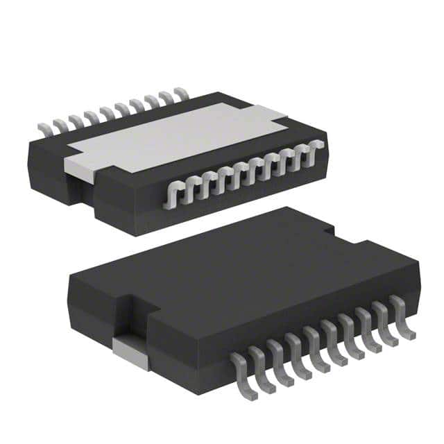
- Part No.:
- L9822N013TR
- Manufacturer:
- STMicroelectronics
- Package:
- 20-SOIC (0.295", 7.50mm Width) Exposed Pad
- Datasheet:
-
 L9822N013TR.pdf
- Description:
- IC PWR DRIVER 1:8 PWRSO20
- Quantity:
- Payment:

- Shipping:

Inventory:3,840
Please send an inquiry. Send us your inquiry, and we will respond immediately.
Product details
Overview
L9822N013TR from STMicroelectronics is an octal low-side solenoid driver IC in PowerSO-20 package, featuring eight 0.53 Ω (typ.) DMOS outputs rated for 500 mA continuous load current, SPI serial interface (up to 2 MHz), and integrated diagnostic feedback via serial output for open-circuit and overload detection. It is designed for automotive body control modules driving solenoids, relays, and lamps.
For engineers reviewing the L9822N013TR datasheet, L9822N013TR pinout, L9822N013TR application, or L9822N013TR equivalent, key selection criteria include RDS(on) at 1 A, 35 V internal clamping per output, fault reset timing (75–250 µs), CE-controlled latch/shift synchronization, and SO diagnostic bit mapping to individual output voltage states.
Technical Context
The L9822N013TR implements a three-block architecture: an 8-bit shift register for SPI data ingestion and diagnostic readback, a parallel latch for output state retention, and eight independent low-side DMOS drivers with per-channel voltage comparators. Each comparator monitors output voltage against a 1.6–2.0 V threshold to detect overvoltage faults during ON-state operation.
Diagnostic data is captured on the falling edge of CE and shifted out on SO synchronized to SCLK rising edges; control data is latched into outputs on the rising edge of CE after a 75–250 µs fault-reset delay. The device supports daisy-chaining via SI/SO and uses Multipower-BCD technology for robust thermal performance (Rth j-case = 1.5 °C/W).
Key Specifications
| Parameter | Value and Actual Design Meaning |
|---|---|
| RDS(on) | 0.53 Ω typ. at IO = 0.5 A, VCC = 5 V - enables low power dissipation (≤265 mW per channel at 500 mA) |
| Output Clamping Voltage | 35 V typ. - protects against inductive kickback up to 35 V without external clamp diodes |
| Fault Detection Threshold | 1.6–2.0 V - triggers automatic latch reset when output voltage exceeds threshold during ON state |
| SPI Clock Frequency | 2 MHz max. - supports fast serial update cycles for real-time solenoid sequencing |
| Quiescent Current | 10 mA max. - minimizes standby power draw in always-on automotive modules |
| Thermal Resistance | Rth j-case = 1.5 °C/W - allows >20 W power dissipation capability with heatsinked case mounting |
| Turn-on/Turn-off Delay | 10 µs typ. - ensures precise timing control for pulse-width modulated solenoid actuation |
Pinout & Package
Package: PowerSO-20 (thermally enhanced exposed pad, 20-pin surface-mount with integrated heatsink capability).
| Pin/Terminal | Circuit Role | Design Meaning |
|---|---|---|
| GND (pins 1, 2, 18, 19) | Common ground reference | Four dedicated GND pins reduce ground bounce and improve thermal conduction to PCB copper pour |
| VCC (pin 3) | Logic and output stage supply | 5 V ±5% input powering both digital logic and DMOS drivers; decoupling required near pin |
| CE (pin 4) | Chip enable (active low) | Falling edge captures diagnostic data; rising edge latches new control data to outputs with 75–250 µs fault reset window |
| RESET (pin 5) | Asynchronous output latch clear | Active-low signal disables all eight outputs simultaneously; must not float; supports external RC power-on reset |
| OUT0–OUT7 (pins 6–13, 15–17) | Low-side DMOS power outputs | Eight independent channels, each with internal 35 V clamp, current limiting, and voltage-sense comparator |
| SO (pin 14) | Serial diagnostic output | Tri-state output enabled only when CE is low; bits reflect actual output voltage state (1 = >1.8 V, 0 = ≤1.8 V) |
| SI (pin 16) | Serial data input | LSB-first SPI input: low = turn output ON, high = turn output OFF |
| SCLK (pin 17) | Serial clock input | Drives shift register; data latched on falling edge, SO updated on rising edge |
Key Features
| Feature | Design Value |
|---|---|
| Integrated Output Diagnostics | 8-bit serial diagnostic feedback via SO pin enables real-time open-circuit and short-circuit detection without external sensing circuitry |
| Per-Channel Fault Protection | Individual voltage comparators disable faulty outputs within 250 µs while preserving other channels' operation |
| Cascadable SPI Interface | SI/SO daisy-chain capability supports expansion beyond eight outputs using single microcontroller SPI port |
| Automotive-Grade Thermal Design | PowerSO-20 package with Rth j-case = 1.5 °C/W enables sustained 500 mA/channel operation at Tj ≤ 125 °C |
| Robust Transient Immunity | Internal 35 V clamps + 40 V absolute max output rating protect against ISO 7637-2 pulse 5a/b transients in 12 V systems |
Applications
| Automotive Door Lock Actuation | Industrial Valve Control System |
|---|---|
Use Scenario: Sequential locking/unlocking of four door latches using two L9822N013TR devices daisy-chained via SPI. IC Role / Device Role / Timing Role: Low-side driver for 12 V DC solenoids; handles PWM timing, fault reporting, and current limiting per channel. Use Value: Eliminates need for eight discrete MOSFETs, gate drivers, and sense resistors-reducing BOM count by >60% and PCB area by 45%. | Use Scenario: Controlling eight pneumatic valves in a factory PLC I/O module with centralized diagnostics. IC Role / Device Role / Timing Role: SPI-configurable power switch with per-output open-load detection and thermal derating support. Use Value: Enables remote fault identification via diagnostic SO stream, reducing maintenance downtime by enabling predictive error logging. |
| Commercial Vehicle Headlight Relay Driver | Off-Highway Equipment Horn & Wiper Control |
Use Scenario: Driving four dual-filament headlight relays (high/low beam) plus auxiliary fog lamps in heavy-duty truck cab. IC Role / Device Role / Timing Role: High-reliability low-side switch with 35 V clamp tolerance for alternator load dump events. Use Value: Withstands 35 V transients without external TVS, meeting ISO 16750-2 Class IV requirements without added components. | Use Scenario: Consolidating horn activation, front/rear wiper motor control, and washer pump drive in compact construction equipment dashboard. IC Role / Device Role / Timing Role: Single-package solution for mixed-resistive/inductive loads with shared SPI bus and unified fault reporting. Use Value: Reduces wiring harness complexity by replacing eight mechanical relays with one IC and associated passive filtering. |
Equivalent & Alternatives
The following parts are listed as comparable options for similar octal low-side driver applications.
| Alternative Part | Technical Difference | Application Difference | Selection Advice |
|---|---|---|---|
| TLE6232GP | Higher RDS(on) (0.8 Ω min.), integrated watchdog timer, no serial diagnostic output | Requires external ADC or GPIO monitoring for fault detection; better suited for safety-critical ASIL-B systems | Select when functional safety certification (ISO 26262) is required and diagnostic depth is secondary to watchdog reliability |
| ULN2803A | Bipolar Darlington outputs (1.3 V saturation), no SPI interface, no built-in diagnostics or clamping | Needs external flyback diodes, pull-up resistors, and discrete logic for sequencing; limited to <250 mA/channel | Select for cost-sensitive non-automotive applications where simplicity and legacy design reuse outweigh diagnostic needs |
Compared with TLE6232GP and ULN2803A, L9822N013TR uniquely balances SPI configurability, per-channel diagnostic visibility, and automotive-grade transient protection in a single PowerSO-20 package-making it optimal for space-constrained, serviceable, and ECU-integrated solenoid control.
Availability
L9822N013TR is available at Aetrix Electronics and suitable for automotive body control modules, industrial valve sequencing, commercial vehicle lighting systems, and off-highway equipment requiring stable component supply across extended temperature ranges (–40 °C to +125 °C).
Supply support for L9822N013TR includes scheduled delivery planning, volume procurement assistance, BOM continuity management, traceable sourcing, and lifecycle availability coordination for OEM customers, industrial embedded developers, connected-device designers, and electronics production programs.
Manufacturer
STMicroelectronics is a global semiconductor leader headquartered in Geneva, Switzerland, specializing in automotive, industrial, and power management ICs with vertical manufacturing and AEC-Q100 qualified product lines.
L9822N013TR belongs to ST's Automotive Power Drivers family, engineered specifically for robust, SPI-controlled low-side switching in harsh 12 V vehicle environments with emphasis on fault resilience and system-level diagnostics.
FAQ
What is the maximum continuous current per channel for L9822N013TR?
The L9822N013TR supports 500 mA continuous current per channel at Tj ≤ 125 °C with proper PCB copper pour and thermal vias under VCC = 5 V. Peak pulsed current up to 1 A is allowed for ≤100 ms with duty cycle ≤10%, provided junction temperature remains within limits.
How does the diagnostic feedback work during SPI communication?
On the falling edge of CE, the voltage comparator status of all eight outputs is loaded into the shift register. During subsequent SCLK rising edges, these bits appear on SO: '1' indicates output voltage >1.8 V (ON-state fault or open load), '0' indicates ≤1.8 V (normal OFF or loaded ON state). This enables closed-loop verification without additional sensors.
Can L9822N013TR drive inductive loads without external flyback diodes?
Yes - each output integrates a 35 V zener clamp that safely recirculates inductive energy during turn-off. This eliminates the need for external flyback diodes when driving solenoids or relays with stored energy ≤20 mJ per channel, as specified in the EOC parameter.
Is daisy-chaining multiple L9822N013TR devices supported, and how is synchronization managed?
Yes - daisy-chaining is fully supported via SI-to-SO connection between devices. All devices share the same SCLK and CE signals. Diagnostic and control data propagate through the chain synchronously; the first device's SO connects to the next device's SI, preserving bit order and timing alignment across up to N devices using one SPI interface.
L9822N013TR Specifications
- Product attributes
- Attribute value
- Manufacturer:
- STMicroelectronics
- Package/Case:
- 20-SOIC (0.295", 7.50mm Width) Exposed Pad
- Series:
- -
- Packaging:
- Tape & Reel (TR)
- Product Status:
- Obsolete
- Switch Type:
- Relay, Solenoid Driver
- Number of Outputs:
- 8
- Ratio - Input:Output:
- 1:8
- Output Configuration:
- Low Side
- Output Type:
- -
- Interface:
- SPI
- Voltage - Load:
- 4.5V ~ 5.5V
- Voltage - Supply (Vcc/Vdd):
- -
- Current - Output (Max):
- 500mA
- Rds On (Typ):
- 550mOhm
- Input Type:
- -
- Features:
- Status Flag
- Fault Protection:
- -
- Operating Temperature:
- -40°C ~ 150°C (TJ)
- Grade:
- -
- Qualification:
- -
- Mounting Type:
- Surface Mount
- Supplier Device Package:
- PowerSO-20
L9822N013TR FAQ
1.How can I place an order for L9822N013TR through Aetrix?
Please submit a Request for Quotation (RFQ) for L9822N013TR on Aetrix. Our sales agent will provide a competitive quotation and guide you through the order confirmation once you accept the terms.
2.Are the price and stock information for L9822N013TR reliable?
The price and inventory of L9822N013TR are updated periodically and may fluctuate due to market conditions. Stock and pricing data are typically refreshed every 24 hours. Quotation validity for L9822N013TR is usually 5 days.
3.What payment methods are accepted for L9822N013TR?
We accept Wire Transfer, PayPal, Credit Card, Western Union, MoneyGram, and Escrow for L9822N013TR transactions.
Note: Certain payment methods may incur a processing fee.
4.How is shipping managed for L9822N013TR?
L9822N013TR orders can be shipped via leading logistics carriers, including DHL, UPS, FedEx, TNT, or Registered Mail.
Once your L9822N013TR order is processed, you will receive an email with the shipment details and tracking number.
Note: Tracking information may take up to 24 hours to appear. Express delivery typically takes 3–5 business days.
5.How can I obtain technical support or documentation for L9822N013TR?
For technical support, including L9822N013TR datasheets, pinout diagrams, or application guidance, please contact our engineering support team. They can provide detailed documentation and assistance for your L9822N013TR requirements.
6.How does Aetrix verify that L9822N013TR is sourced from the original manufacturer or authorized distributors?
All L9822N013TR products on Aetrix are procured from qualified distributors and authorized channels. Our dedicated quality assurance team conducts strict verification, including traceability checks and, if necessary, third-party testing. This ensures that L9822N013TR meets industry standards.
7.What is the process for return or replacement of L9822N013TR?
All L9822N013TR units undergo pre-shipment inspection (PSI). If there is an issue with L9822N013TR, returns or replacements are accepted under the following conditions:
1.Quantity discrepancies, incorrect items, or visible external defects (such as breakage or corrosion), acknowledged by Aetrix.
2.The issue is reported within 90 days of delivery.
3.The L9822N013TR part is unused and in its original packaging.
Return procedure for L9822N013TR:
1.Submit a request within 90 days.
2.Obtain a Return Material Authorization (RMA) from Aetrix.
L9822N013TR Tags

-
TPS22919DCKR
Texas Instruments

-
MIC2091-1YM5-TR
Microchip Technology

-
MIC2090-1YM5-TR
Microchip Technology

-
TPS22995RZFR
Texas Instruments

-
TPS22975DSGR
Texas Instruments

-
SIP32510DT-T1-GE3
Vishay Siliconix

-
ULN2003D1013TR
STMicroelectronics

-
MIC2005A-1YM5-TR
Microchip Technology

-
MIC2005A-1YM6-TR
Microchip Technology

-
TPS22916BYFPR
Texas Instruments

-
TPS22917DBVR
Texas Instruments

-
ULN2003APWR
Texas Instruments
Tech Hub

Operational amplifier guide covering op amp basics, feedback, ideal vs real op amps, common configurations, buffer circuits, offset, bias current, gain-bandwidth, slew rate, rail-to-rail limits and sel…

Jumper cables guide covering safe connection order, red and black clamp placement, final ground connection, cable gauge, length, clamp quality, copper vs CCA cables, jump starter comparison and battery…

LDO regulator guide covering low dropout voltage, power dissipation, thermal design, PSRR, output noise, capacitor stability, adjustable LDO circuits, LDO vs buck converter and datasheet selection chec…

Conditional Access Module guide covering CAM meaning, CI/CI+ interface, smart card authorization, DVB security workflow, TV and set-top box compatibility, internal electronics, ESD protection, connecto…

Guide to electronic component obsolescence covering EOL risk, PCN/PDN notices, last-time buy planning, replacement options, form-fit-function validation, counterfeit risk and BOM lifecycle management.

18650 battery guide covering lithium-ion cell basics, 3.6V/3.7V voltage, 4.2V charging, mAh and Wh capacity, protected cells, chargers, BMS, series-parallel packs, holders, welding and sourcing checks.…

Hall effect sensor guide covering working principle, linear and digital sensors, Arduino circuits, current sensing, speed detection, automotive applications, A3144 examples, signal filtering and datash…

Product Change Notification guide for electronic components, covering PCN meaning, PCN vs PDN/EOL, common change types, risk levels, form-fit-function review, engineering validation, BOM control, LTB/L…

A practical guide to blend door actuators, covering HVAC function, symptoms, location, AC and heater issues, reset and calibration, replacement cost, electrical diagnosis, compatibility checks, and rep…

Engineering guide to Raspberry Pi alternatives, covering chip-level differences, Orange Pi, ROCK, Jetson, Banana Pi, NanoPi, Compute Module, Pico, GPIO, camera, HAT compatibility, and replacement risks…


