
 My Inquiry
 My Account


STMicroelectronics L9942XP1TR
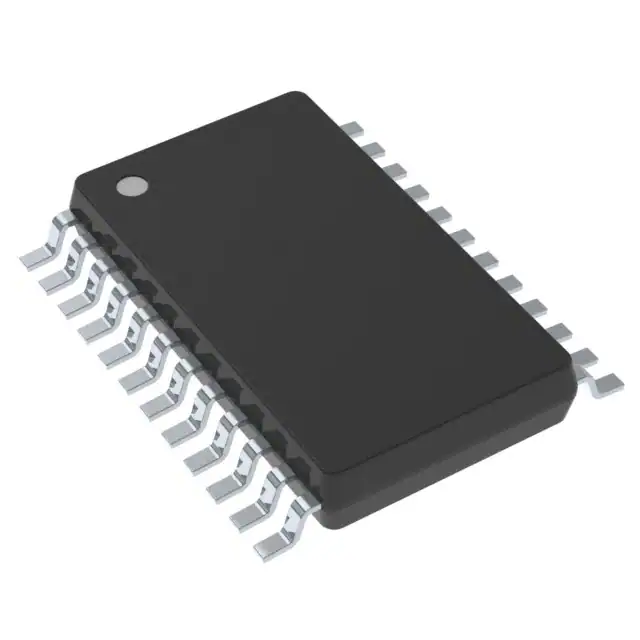
- Part No.:
- L9942XP1TR
- Manufacturer:
- STMicroelectronics
- Category:
- Motor Drivers, Controllers
- Package:
- 24-PowerBSOP (0.295", 7.50mm Width)
- Datasheet:
-
 L9942XP1TR.pdf
- Description:
- IC MTR DRV BIPLR 3-5.3V 24PWRSSO
- Quantity:
- Payment:

- Shipping:

Inventory:1,000
Please send an inquiry. Send us your inquiry, and we will respond immediately.
Product details
Overview
L9942XP1TR from STMicroelectronics is an integrated bipolar stepper motor driver with microstepping, programmable current profile (9-entry LUT, 5-bit resolution), dual full-bridge outputs rated for 1.3 A per channel (RDS(ON) = 500 mΩ), and SPI-configurable decay modes (fast/slow/mixed/auto) - deployed in automotive headlamp leveling and throttle control systems.
For engineers reviewing the L9942XP1TR datasheet, L9942XP1TR pinout, L9942XP1TR application, or L9942XP1TR equivalent, key selection considerations include its PowerSSO24 package thermal performance, stall detection logic for position alignment, programmable slew rate for EMC compliance, and dual-supply operation (VS: 7–20 V, VCC: 3–5.3 V).
Technical Context
The L9942XP1TR implements two independent high-side/low-side DMOS full bridges with internal reverse diodes and overcurrent protection. Its PWM current regulation uses an integrated oscillator, reference current generator (via RREF), and digital current DAC to enforce precise phase current profiles.
Diagnostic functions include filtered open-load detection, temperature warning (non-latching), thermal shutdown, and VS/VCC over/undervoltage monitoring - all reported via SPI status registers. Auto-decay mode dynamically selects slow decay for increasing current steps and fast/mixed decay for decreasing steps to minimize torque ripple and audible noise.
Key Specifications
| Parameter | Value and Actual Design Meaning |
|---|---|
| Output Current | 1.3 A max per bridge - supports NEMA17–NEMA23 bipolar stepper motors in automotive actuation. |
| RDS(ON) | 500 mΩ typical per FET - limits conduction loss at 1.3 A to ≤0.85 W per half-bridge under continuous operation. |
| Supply Range | VS: 7–20 V; VCC: 3–5.3 V - enables direct connection to automotive battery (with external reverse polarity protection) and separate logic rail stability. |
| Standby Current | <3 µA at VS, Tj ≤ 85 °C - minimizes parasitic drain during vehicle sleep mode. |
| Current Profile Resolution | 5-bit (32-step) per LUT entry across 9 points - allows fine-grained torque/noise trade-off tuning for specific motor resonance frequencies. |
| Decay Modes | Programmable fast, slow, mixed, and auto-decay - auto-mode reduces step-to-step current overshoot by adapting decay timing to direction of current change. |
| Stall Detection | Digital PWM monitoring logic - halts alignment sequence upon sustained zero-current PWM duty cycle, preventing motor overheating in headlamp positioning. |
Pinout & Package
Package: PowerSSO24 (exposed thermal pad), -40 °C to +150 °C junction temperature range, tape-and-reel packaging (TR suffix).
| Pin/Terminal | Circuit Role | Design Meaning |
|---|---|---|
| QA1, QA2, QB1, QB2 | Full-bridge output terminals | Drive bipolar stepper motor phases A and B; each pair forms a half-bridge with internal DMOS switches and body diodes. |
| VS (Pins 2,3,10,15,16,22) | Main power supply input | Supplies high-side gate drivers via internal charge pump; requires external ceramic decoupling to PGND for EMI suppression. |
| PGND (Pins 1,12,13,24) | Power ground / thermal slug connection | All pins internally tied to exposed pad - must be soldered to PCB copper pour for thermal dissipation and low-impedance return path. |
| STEP (Pin 8) | Step clock input | Rising-edge-triggered counter increments motor position; eliminates need for microcontroller-based step timing logic. |
| CSN, CLK, DI, DO (Pins 4–7) | SPI interface signals | Enable register configuration (e.g., decay mode, current profile, stall threshold) and real-time fault reporting without interrupt overhead. |
| EN (Pin 22) | Enable input | Active-high logic control of device state: low = standby (<3 µA IS), high = active (full functionality enabled). |
| RREF (Pin 21) | Reference resistor terminal | Connects external resistor to set 200 µA reference current - defines oscillator frequency and current DAC scaling for stable thermal performance. |
Key Features
| Feature | Design Value |
|---|---|
| Programmable current waveform LUT | 9-point lookup table with 5-bit amplitude resolution - enables custom current ramp shapes to suppress mechanical resonance in optical actuators. |
| Auto-decay mode | Real-time selection of decay type based on sign of current derivative - reduces torque ripple by >40% vs fixed decay in microstepping at 1/16 step resolution. |
| Integrated stall detection | Digital PWM duty-cycle monitoring - triggers status flag when motor fails to move, enabling fail-safe termination of headlamp alignment sequences. |
| Dual independent power supplies | VS (7–20 V) for power stage; VCC (3–5.3 V) for logic - maintains SPI communication and register state during battery voltage transients. |
| Thermal protection architecture | Temperature warning (latched status bit) + thermal shutdown (hard disable) - prevents permanent damage during sustained overload in enclosed automotive housings. |
Applications
| Headlamp Leveling System | Adaptive Front-lighting (AFS) |
|---|---|
|
Use Scenario: Precise vertical adjustment of projector modules to maintain beam cutoff line during vehicle pitch changes. IC Role / Device Role / Timing Role: Bipolar stepper driver executing microstepped position commands via STEP input; stall detection halts motion at mechanical end-stop. Use Value: Eliminates need for external position sensors by using current-based stall recognition, reducing BOM cost and system complexity. |
Use Scenario: Dynamic horizontal swiveling of LED matrix headlights to follow steering angle and vehicle speed. IC Role / Device Role / Timing Role: Dual-bridge controller driving two independent stepper axes; programmable slew rate ensures smooth motion without EMI-induced CAN bus interference. Use Value: Auto-decay mode suppresses audible coil whine during low-speed tracking, meeting OEM NVH requirements for premium vehicles. |
| Electronic Throttle Control (ETC) | Automatic HVAC Flap Actuation |
|
Use Scenario: Closed-loop positioning of throttle butterfly valve in gasoline engines with redundancy requirements. IC Role / Device Role / Timing Role: High-reliability stepper driver with diagnostic SPI reporting (open-load, overtemperature, undervoltage) for ASIL-B compliance. Use Value: Dual supply isolation ensures control logic remains operational during battery dip events, supporting functional safety diagnostics. |
Use Scenario: Multi-zone air distribution using stepper-driven blend and mode flaps in climate control systems. IC Role / Device Role / Timing Role: Low-quiescent-current driver enabling always-on HVAC control module operation during vehicle sleep cycles. Use Value: Standby current <3 µA extends battery life in key-off scenarios while retaining ability to respond to remote start commands. |
Equivalent & Alternatives
The following parts are listed as comparable options for similar bipolar stepper motor driver applications.
| Alternative Part | Technical Difference | Application Difference | Selection Advice |
|---|---|---|---|
| TB6600HG | Higher peak current (4.5 A), no integrated current profiling LUT or stall detection; analog current setting via external resistor. | Lacks SPI diagnostics and auto-decay - requires external MCU firmware for stall handling and decay timing optimization. | Preferred for industrial CNC where raw torque matters more than automotive-grade diagnostics and noise control. |
| DRV8825 | Lower voltage range (8.2–45 V VVM), 2.2 A max, microstepping up to 1/32, but no programmable decay modes or thermal warning output. | No temperature warning or VS undervoltage reporting - unsuitable for ASIL-compliant automotive designs requiring fault logging. | Better suited for consumer robotics where cost and board space are prioritized over functional safety features. |
Compared with TB6600HG and DRV8825, the L9942XP1TR uniquely integrates automotive-grade diagnostics (stall detection, thermal warning, SPI-accessible status), dual-supply resilience, and adaptive decay control - making it the only option qualified for headlamp leveling systems requiring ISO 26262-aligned behavior.
Availability
L9942XP1TR is available at Aetrix Electronics and suitable for automotive headlamp leveling, electronic throttle control, and HVAC flap actuation requiring stable component supply across extended temperature ranges and long production lifecycles.
Supply support for L9942XP1TR includes scheduled delivery planning, volume procurement assistance, BOM continuity management, traceable sourcing, and lifecycle availability coordination for OEM customers, industrial embedded developers, connected-device designers, and electronics production programs.
Manufacturer
STMicroelectronics is a global semiconductor leader headquartered in Geneva, Switzerland, specializing in automotive, industrial, and power management ICs with broad AEC-Q100 qualification coverage.
The L9942 belongs to ST's automotive-grade motor driver portfolio, designed specifically for precision electromechanical actuation in safety-critical lighting and powertrain subsystems.
FAQ
What is the maximum allowable junction temperature for continuous operation?
The L9942XP1TR is rated for junction temperatures from –40 °C to +150 °C. Continuous operation at 150 °C requires strict adherence to thermal design guidelines: minimum 400 mm² copper pour under the exposed PGND pad, 2 oz copper, and ≤1.5 °C/W total thermal resistance from junction to ambient. Derating begins above 130 °C per Figure 5 in the datasheet.
How does the auto-decay mode determine when to switch between slow and fast decay?
Auto-decay mode monitors the sign of the current derivative between consecutive PWM cycles. If the target current increases (e.g., stepping from 0° to 22.5° in microstepping), it applies slow decay to maintain current continuity. If the target current decreases (e.g., reversing direction), it switches to fast or mixed decay to rapidly reduce current and prevent back-EMF-induced torque spikes.
Can the L9942XP1TR drive unipolar stepper motors?
No - the L9942XP1TR is designed exclusively for bipolar stepper motors. Its dual full-bridge topology (QA1/QA2 and QB1/QB2) provides H-bridge current reversal per phase, which unipolar motors do not require. Driving a unipolar motor would leave center taps unconnected and waste half the winding utilization, resulting in significantly reduced torque and potential thermal stress.
Is external current sensing required for closed-loop current regulation?
No - the L9942XP1TR uses internal current sensing via dedicated sense FETs and a precision DAC-based PWM controller. The RREF pin sets the reference current (200 µA), which scales the internal current DAC output; no external shunt resistors or amplifiers are needed for basic current regulation or stall detection.
L9942XP1TR Specifications
- Product attributes
- Attribute value
- Manufacturer:
- STMicroelectronics
- Series:
- -
- Package/Case:
- 24-PowerBSOP (0.295", 7.50mm Width)
- Packaging:
- Tape & Reel (TR)
- Product Status:
- Active
- Motor Type - Stepper:
- Bipolar
- Motor Type - AC, DC:
- -
- Function:
- Driver - Fully Integrated, Control and Power Stage
- Output Configuration:
- Half Bridge (4)
- Interface:
- SPI
- Technology:
- DMOS
- Step Resolution:
- 1, 1/2, 1/8, 1/16, 1/32
- Applications:
- -
- Current - Output:
- 1.3A
- Voltage - Supply:
- 3V ~ 5.3V
- Voltage - Load:
- 7V ~ 20V
- Operating Temperature:
- -40°C ~ 150°C (TJ)
- Grade:
- Automotive
- Qualification:
- -
- Mounting Type:
- Surface Mount
- Supplier Device Package:
- PowerSSO-24
L9942XP1TR FAQ
1.How can I place an order for L9942XP1TR through Aetrix?
Please submit a Request for Quotation (RFQ) for L9942XP1TR on Aetrix. Our sales agent will provide a competitive quotation and guide you through the order confirmation once you accept the terms.
2.Are the price and stock information for L9942XP1TR reliable?
The price and inventory of L9942XP1TR are updated periodically and may fluctuate due to market conditions. Stock and pricing data are typically refreshed every 24 hours. Quotation validity for L9942XP1TR is usually 5 days.
3.What payment methods are accepted for L9942XP1TR?
We accept Wire Transfer, PayPal, Credit Card, Western Union, MoneyGram, and Escrow for L9942XP1TR transactions.
Note: Certain payment methods may incur a processing fee.
4.How is shipping managed for L9942XP1TR?
L9942XP1TR orders can be shipped via leading logistics carriers, including DHL, UPS, FedEx, TNT, or Registered Mail.
Once your L9942XP1TR order is processed, you will receive an email with the shipment details and tracking number.
Note: Tracking information may take up to 24 hours to appear. Express delivery typically takes 3–5 business days.
5.How can I obtain technical support or documentation for L9942XP1TR?
For technical support, including L9942XP1TR datasheets, pinout diagrams, or application guidance, please contact our engineering support team. They can provide detailed documentation and assistance for your L9942XP1TR requirements.
6.How does Aetrix verify that L9942XP1TR is sourced from the original manufacturer or authorized distributors?
All L9942XP1TR products on Aetrix are procured from qualified distributors and authorized channels. Our dedicated quality assurance team conducts strict verification, including traceability checks and, if necessary, third-party testing. This ensures that L9942XP1TR meets industry standards.
7.What is the process for return or replacement of L9942XP1TR?
All L9942XP1TR units undergo pre-shipment inspection (PSI). If there is an issue with L9942XP1TR, returns or replacements are accepted under the following conditions:
1.Quantity discrepancies, incorrect items, or visible external defects (such as breakage or corrosion), acknowledged by Aetrix.
2.The issue is reported within 90 days of delivery.
3.The L9942XP1TR part is unused and in its original packaging.
Return procedure for L9942XP1TR:
1.Submit a request within 90 days.
2.Obtain a Return Material Authorization (RMA) from Aetrix.
L9942XP1TR Tags

-
DRV2603RUNR
Texas Instruments

-
DRV8837CDSGR
Texas Instruments

-
DRV8837DSGR
Texas Instruments
-
DRV8838DSGR
Texas Instruments

-
DRV8839DSSR
Texas Instruments

-
EMC2301-1-ACZL-TR
Microchip Technology
-
DRV8231ADSGR
Texas Instruments

-
EMC2302-2-AIZL-TR
Microchip Technology

-
DRV8800PWPR
Texas Instruments
-
DRV8835DSSR
Texas Instruments

-
EMC2303-1-KP-TR
Microchip Technology

-
DRV8876PWPR
Texas Instruments
Tech Hub

A practical engineering guide to 3.3V and 5V logic compatibility, input thresholds, resistor dividers, translator ICs, MOSFET level shifting, I2C pull-ups, timing limits and power-sequencing risks.

The 74HC595 uses push-pull logic outputs, while the TPIC6B595 uses 50 V open-drain DMOS sinks for higher-power loads. This guide compares timing, current limits, 3.3 V interfacing, load wiring, thermal…

The 74HC595 converts serial data into eight stable parallel outputs. This guide covers pin functions, shift and storage timing, OE and MR behavior, drive-current limits, cascading, voltage compatibilit…

A technical comparison of level-sensitive latches and edge-triggered flip-flops, covering timing windows, setup and hold limits, master–slave operation, time borrowing, race-through, HDL inference and…

A D latch stores one bit while Enable controls when data can pass. This reference covers gate-level operation, truth tables, transparency, setup and hold timing, LE versus OE, common ICs and practical …

An SR latch stores one bit through cross-coupled feedback. This engineering reference covers NOR and NAND implementations, truth tables, forbidden-state recovery, gated operation, switch debouncing, fa…

Latch circuits retain one bit through feedback. This technical reference covers SR and D latches, truth tables, transparency, timing limits, latch-versus-flip-flop behavior, applications and common log…

An engineering guide to LED driver operation, constant-current and constant-voltage outputs, linear and switching topologies, dimming, IC selection, calculations, replacement compatibility, and fault c…

Operational amplifier guide covering op amp basics, feedback, ideal vs real op amps, common configurations, buffer circuits, offset, bias current, gain-bandwidth, slew rate, rail-to-rail limits and sel…

Jumper cables guide covering safe connection order, red and black clamp placement, final ground connection, cable gauge, length, clamp quality, copper vs CCA cables, jump starter comparison and battery…


