
 My Inquiry
 My Account


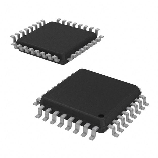
STMicroelectronics L99LD01TR-E
- Part No.:
- L99LD01TR-E
- Manufacturer:
- STMicroelectronics
- Category:
- LED Drivers
- Package:
- 32-LQFP
- Datasheet:
-
 L99LD01TR-E.pdf
- Description:
- IC LED DRIVER CTRLR PWM 32LQFP
- Quantity:
- Payment:

- Shipping:

Inventory:2,331
Please send an inquiry. Send us your inquiry, and we will respond immediately.
Product details
Overview
L99LD01TR-E from STMicroelectronics is an AEC-Q100 qualified, high-efficiency constant-current DC–DC LED driver IC for automotive headlamp systems, supporting Boost, Buck-Boost, and Flyback topologies. It delivers precise ±2% 5 V regulated micro supply (20 mA), features SPI-programmable LED current (±66.7%), input current limiting (±55.5%), and internal spread-spectrum dithering (100–500 kHz) to reduce EMC emissions in demanding vehicle environments.
For engineers reviewing the L99LD01TR-E datasheet, L99LD01TR-E pinout, L99LD01TR-E application, or L99LD01TR-E equivalent, this page provides verified technical context, validated pin functions, topology-specific operating modes (including limp-home and software limp-home), and real-world design implications of slope compensation, battery overvoltage shutdown, and multiplexed LED temperature/voltage monitoring via NTC and MOUT.
Technical Context
The L99LD01TR-E integrates a programmable current-mode PWM controller with internal slope compensation adjustable via external resistor R9, ensuring loop stability across variable duty cycles in Boost/Buck-Boost/Flyback configurations. Its random dither oscillator modulates switching frequency (100–500 kHz, set by RSF) to suppress narrowband EMI peaks without compromising regulation accuracy.
SPI-controlled operation enables dynamic configuration of LED current reference, maximum input current limit, dither modulation depth/frequency, and diagnostic thresholds. The device supports dual-mode control: full-power operation with microcontroller coordination or standalone mode using ENABLE/LHM pins, with built-in power-on reset, watchdog timer, and thermal shutdown protection.
Key Specifications
| Parameter | Value and Actual Design Meaning |
|---|---|
| Input voltage range | 5.6 V to 24 V - supports full automotive battery range including cold-crank (5.6 V) and load-dump transients (up to 40 V absolute max) |
| Switching frequency | 100–500 kHz - externally adjustable via RSF resistor; internal spread-spectrum dither reduces peak EMI by spectral dispersion |
| LED current accuracy | ±2% typical - achieved via precision current sense amplifier (ISENSE+/−) and programmable reference with ±66.7% adjustment range |
| Regulated outputs | 5 V ±2% @ 20 mA (VCC1); 10 V @ 10 mA (VCC2) - powers external microcontrollers and gate drivers without auxiliary regulators |
| Protections | Battery overvoltage shutdown (via INP_OV), LED chain OV detection (VLED), thermal shutdown, watchdog timeout, and start-up fail recovery |
| SPI interface | ST-standard 4-wire (SDI/SDO/SCK/CSN), 8-bit command/data, global status byte reporting fault conditions and operational state |
| Operating temperature | −40 °C to +150 °C - qualified per AEC-Q100 Grade 0, enabling under-hood headlamp placement |
Pinout & Package
L99LD01TR-E is housed in a thermally enhanced LQFP32™ package (7 × 7 mm, 0.8 mm pitch) with exposed thermal pad for automotive-grade thermal dissipation.
| Pin/Terminal | Circuit Role | Design Meaning |
|---|---|---|
| 1 (VCC1) | 5 V regulator output | Supplies external MCU or logic; requires ≥1 µF ceramic capacitor to GND for stability |
| 2 (NRES) | Open-drain reset output | Active-low signal indicating VCC1 undervoltage or internal fault; pulls down on startup until regulation established |
| 3 (PWM_L) | Low-frequency PWM input | Accepts 0–5 V logic-level dimming signal; enables analog-equivalent brightness control without external MOSFET |
| 4–7 (SDI/SDO/SCK/CSN) | SPI serial interface | Full-duplex communication for register programming, diagnostics, and multiplexed sensor readout (NTC, VLED) |
| 8 (MOUT) | Multiplexed analog output | Time-shared output for NTC voltage, LED chain voltage (VLED), or low-frequency PWM feedback-selected via SPI command |
| 15 (NTC) | NTC bias/sense node | Provides current source for external NTC thermistor; enables closed-loop LED temperature compensation |
| 17 (VLED) | LED chain overvoltage monitor | High-impedance input for resistor-divider feedback; triggers OV fault if LED voltage exceeds programmed threshold |
| 19 & 24 (G2/G1) | External PMOS gate drivers | High-side drivers (10 V VCC2 referenced) for synchronous rectification or high-side switch control in Boost/Flyback |
| 20–21 (ISENSE−/ISENSE+) | Current sense differential inputs | Measures voltage drop across external shunt to regulate LED current with <1 mV offset error |
| 30 (VS) | Main battery input | Connects directly to automotive battery (5.6–24 V); withstands 40 V transient per ABSOLUTE MAX rating |
| 31 (SC) | Slope compensation adjust | External resistor sets compensation ramp slope to prevent subharmonic oscillation at >50% duty cycle |
| 32 (RSF) | Oscillator frequency set | Resistor value directly programs nominal switching frequency between 100 kHz and 500 kHz |
Key Features
| Feature | Design Value |
|---|---|
| Automotive qualification | AEC-Q100 Grade 0 (−40 °C to +150 °C ambient), ISO 16750-2 compliant for electrical stress, and PPAP-ready |
| Programmable current regulation | SPI-adjustable LED current reference with ±66.7% range compensates for LED binning and aging drift |
| EMC-optimized switching | Internal random dither oscillator spreads 100–500 kHz fundamental across ±10% bandwidth, reducing peak radiated emissions by >10 dBµV/m |
| Limp-home safety mode | Dedicated LHM pin forces fixed 50% duty cycle on G1/G2 during MCU failure-maintains partial headlamp illumination for safe vehicle operation |
| Integrated diagnostics | Real-time fault reporting (OV, OT, watchdog timeout) via SPI status byte and hardware NRES assertion |
| Multiplexed sensor interface | Single MOUT pin sequentially delivers NTC voltage, VLED, and PWM_L feedback-reduces MCU ADC channel count and BOM cost |
Applications
| Automotive Daytime Running Lights (DRL) | Adaptive Front-Lighting Systems (AFS) |
|---|---|
|
Use Scenario: Continuous low-power LED illumination during daylight hours for vehicle conspicuity. IC Role / Device Role / Timing Role: Constant-current driver regulating 350 mA–1.5 A through multi-string LED arrays; operates in full-power mode with SPI-set current and dither-enabled EMC compliance. Use Value: Delivers stable light output across battery voltage swings (9–16 V) while meeting CISPR 25 Class 5 radiated emissions limits without added shielding or filtering. |
Use Scenario: Dynamic beam shaping using segmented LED arrays controlled by steering angle and speed inputs. IC Role / Device Role / Timing Role: High-accuracy current source for individual LED zones; leverages MOUT multiplexing to monitor per-zone temperature and voltage in real time via MCU ADC. Use Value: Enables closed-loop thermal derating and adaptive current scaling-prevents localized LED overheating and maintains consistent lumen output during cornering maneuvers. |
| LED Headlamp Low Beam | LED Headlamp High Beam |
|
Use Scenario: Primary forward illumination with cutoff pattern, requiring stable 700 mA–2 A drive and robust fault handling. IC Role / Device Role / Timing Role: Core DC–DC controller in Boost topology; uses slope compensation (SC pin) and battery OV shutdown (INP_OV) to maintain regulation during engine cranking and load dump. Use Value: Guarantees uninterrupted low-beam operation during 5.6 V cold-crank and 35 V load-dump events-no flicker or dropout due to integrated protections and wide VS range. |
Use Scenario: High-intensity beam activated intermittently for highway visibility, demanding fast response and thermal resilience. IC Role / Device Role / Timing Role: Buck-Boost driver with limp-home mode (LHM pin); defaults to 50% duty cycle on G1/G2 if MCU fails-preserves partial high-beam function. Use Value: Meets FMVSS 108/UNECE R112 functional safety requirements by maintaining minimum illumination level during electronic failure-no complete beam loss. |
Equivalent & Alternatives
The following parts are listed as comparable options for similar constant-current LED driver applications.
| Alternative Part | Technical Difference | Application Difference | Selection Advice |
|---|---|---|---|
| AL8862Q-13 | Fixed-frequency (2.2 MHz) buck-only topology; no spread spectrum; no limp-home mode; SPI absent | Targeted at compact DRL modules where size > EMC performance; lacks multiplexed sensing and standalone operation | Choose when board space is critical and only basic constant-current drive is needed-no headlamp-level safety or diagnostics required |
| TLC59621RTQT | 16-channel linear LED sink driver; no DC–DC conversion; 5.5 V max input; I²C interface only | Designed for interior RGB lighting or low-power signage-not suitable for high-voltage automotive headlamps | Use only for low-power (<100 mA/channel), low-VS (<5.5 V), non-safety-critical applications-cannot replace L99LD01TR-E in headlamp designs |
Compared with AL8862Q-13 and TLC59621RTQT, the L99LD01TR-E uniquely combines Boost/Buck-Boost/Flyback flexibility, AEC-Q100 Grade 0 operation, SPI-configurable protections, and certified limp-home functionality-making it the only viable option for ASIL-B-compliant front-lighting systems requiring functional safety and field-programmable behavior.
Availability
L99LD01TR-E is available at Aetrix Electronics and suitable for automotive headlamp systems, daytime running lights, and adaptive front-lighting applications requiring stable component supply, long-term lifecycle support, and AEC-Q100 compliance.
Supply support for L99LD01TR-E includes scheduled delivery planning, volume procurement assistance, BOM continuity management, traceable sourcing, and lifecycle availability coordination for OEM customers, industrial embedded developers, connected-device designers, and electronics production programs.
Manufacturer
STMicroelectronics is a global semiconductor leader specializing in automotive, industrial, and power management ICs, with broad manufacturing scale and automotive qualification expertise.
The L99LD01TR-E belongs to ST's automotive LED driver product line, engineered specifically for functional-safety-critical front-lighting systems requiring high efficiency, EMC robustness, and ASIL-aware fault handling in harsh vehicle environments.
FAQ
What topologies does the L99LD01TR-E support, and how is topology selection implemented?
The L99LD01TR-E supports Boost, Buck-Boost, and Flyback converter topologies through external component selection-not internal configuration. Its current-mode controller architecture, dual gate drivers (G1/G2), and flexible feedback paths (VLED, ISENSE±) enable all three without changing IC firmware or registers. Designers select topology by choosing appropriate inductor, transformer, and diode/MOSFET arrangements per application circuit diagrams in Section 7 of the datasheet (DocID025319 Rev 3).
How does the limp-home mode operate, and what hardware signals trigger it?
Limp-home mode activates when the LHM pin is pulled low, forcing G1 and G2 outputs into fixed 50% duty-cycle operation regardless of SPI commands or ENABLE state. This ensures partial LED illumination during MCU failure or software crash. The mode is hardware-latched and persists until LHM returns high or VS is cycled. Recovery paths-including automatic exit upon successful SPI reinitialization-are defined in Table 2 of the datasheet.
Can the L99LD01TR-E drive multiple independent LED strings simultaneously?
No-the L99LD01TR-E regulates current for a single LED string via its ISENSE+/− inputs. To drive multiple independent strings, separate L99LD01TR-E devices are required, each with dedicated current sense resistors and feedback paths. However, multiple units can be synchronized via shared RSF or dither clock signals to minimize beat-frequency EMI in multi-channel headlamp modules.
What is the role of the MOUT pin, and how is its multiplexing controlled?
The MOUT pin sequentially outputs voltage readings for external NTC (temperature), VLED (LED chain voltage), or PWM_L (dimming signal feedback) based on SPI commands written to the MUX_CTRL register (address 0x1A). Each reading is held for ~10 µs before switching; timing and selection protocol are fully documented in Section 3.5 (Control Registers) and Figure 22 (SPI global error information output) of the datasheet.
L99LD01TR-E Specifications
- Product attributes
- Attribute value
- Manufacturer:
- STMicroelectronics
- Series:
- -
- Package/Case:
- 32-LQFP
- Packaging:
- Tape & Reel (TR)
- Product Status:
- Obsolete
- Type:
- DC DC Controller
- Topology:
- Flyback, Step-Down (Buck), Step-Up (Boost)
- Internal Switch(s):
- No
- Number of Outputs:
- 1
- Voltage - Supply (Min):
- 5.6V
- Voltage - Supply (Max):
- 24V
- Voltage - Output:
- -
- Current - Output / Channel:
- -
- Frequency:
- 100kHz ~ 500kHz
- Dimming:
- PWM
- Applications:
- -
- Operating Temperature:
- -40°C ~ 150°C (TJ)
- Grade:
- Automotive
- Qualification:
- -
- Mounting Type:
- Surface Mount
- Supplier Device Package:
- 32-LQFP (7x7)
L99LD01TR-E FAQ
1.How can I place an order for L99LD01TR-E through Aetrix?
Please submit a Request for Quotation (RFQ) for L99LD01TR-E on Aetrix. Our sales agent will provide a competitive quotation and guide you through the order confirmation once you accept the terms.
2.Are the price and stock information for L99LD01TR-E reliable?
The price and inventory of L99LD01TR-E are updated periodically and may fluctuate due to market conditions. Stock and pricing data are typically refreshed every 24 hours. Quotation validity for L99LD01TR-E is usually 5 days.
3.What payment methods are accepted for L99LD01TR-E?
We accept Wire Transfer, PayPal, Credit Card, Western Union, MoneyGram, and Escrow for L99LD01TR-E transactions.
Note: Certain payment methods may incur a processing fee.
4.How is shipping managed for L99LD01TR-E?
L99LD01TR-E orders can be shipped via leading logistics carriers, including DHL, UPS, FedEx, TNT, or Registered Mail.
Once your L99LD01TR-E order is processed, you will receive an email with the shipment details and tracking number.
Note: Tracking information may take up to 24 hours to appear. Express delivery typically takes 3–5 business days.
5.How can I obtain technical support or documentation for L99LD01TR-E?
For technical support, including L99LD01TR-E datasheets, pinout diagrams, or application guidance, please contact our engineering support team. They can provide detailed documentation and assistance for your L99LD01TR-E requirements.
6.How does Aetrix verify that L99LD01TR-E is sourced from the original manufacturer or authorized distributors?
All L99LD01TR-E products on Aetrix are procured from qualified distributors and authorized channels. Our dedicated quality assurance team conducts strict verification, including traceability checks and, if necessary, third-party testing. This ensures that L99LD01TR-E meets industry standards.
7.What is the process for return or replacement of L99LD01TR-E?
All L99LD01TR-E units undergo pre-shipment inspection (PSI). If there is an issue with L99LD01TR-E, returns or replacements are accepted under the following conditions:
1.Quantity discrepancies, incorrect items, or visible external defects (such as breakage or corrosion), acknowledged by Aetrix.
2.The issue is reported within 90 days of delivery.
3.The L99LD01TR-E part is unused and in its original packaging.
Return procedure for L99LD01TR-E:
1.Submit a request within 90 days.
2.Obtain a Return Material Authorization (RMA) from Aetrix.
L99LD01TR-E Tags

-
BCR402RE6327HTSA1
Infineon Technologies

-
BCR430UXTSA2
Infineon Technologies

-
BCR420UE6433HTMA1
Infineon Technologies
-
BCR420UE6327HTSA1
Infineon Technologies
-
BCR421UE6327HTSA1
Infineon Technologies

-
LYT1604D-TL
Power Integrations

-
HV9910CLG-G
Microchip Technology

-
CL2N8-G
Microchip Technology

-
BCR420UW6-7
Diodes Incorporated
-
BCR421UW6-7
Diodes Incorporated

-
BCR420UFD-7
Diodes Incorporated
-
BCR421UFD-7
Diodes Incorporated
Tech Hub

A practical engineering and sourcing framework covering lifecycle verification, lifetime-buy calculations, replacement qualification, supplier checks and counterfeit-risk controls.

TTL and CMOS logic families differ in thresholds, loading, output drive, power and timing. This engineering guide compares 74HC and 74HCT, calculates noise margins and checks 3.3 V/5 V compatibility.

A practical engineering guide to 3.3V and 5V logic compatibility, input thresholds, resistor dividers, translator ICs, MOSFET level shifting, I2C pull-ups, timing limits and power-sequencing risks.

The 74HC595 uses push-pull logic outputs, while the TPIC6B595 uses 50 V open-drain DMOS sinks for higher-power loads. This guide compares timing, current limits, 3.3 V interfacing, load wiring, thermal…

The 74HC595 converts serial data into eight stable parallel outputs. This guide covers pin functions, shift and storage timing, OE and MR behavior, drive-current limits, cascading, voltage compatibilit…

A technical comparison of level-sensitive latches and edge-triggered flip-flops, covering timing windows, setup and hold limits, master–slave operation, time borrowing, race-through, HDL inference and…

A D latch stores one bit while Enable controls when data can pass. This reference covers gate-level operation, truth tables, transparency, setup and hold timing, LE versus OE, common ICs and practical …

An SR latch stores one bit through cross-coupled feedback. This engineering reference covers NOR and NAND implementations, truth tables, forbidden-state recovery, gated operation, switch debouncing, fa…

Latch circuits retain one bit through feedback. This technical reference covers SR and D latches, truth tables, transparency, timing limits, latch-versus-flip-flop behavior, applications and common log…

An engineering guide to LED driver operation, constant-current and constant-voltage outputs, linear and switching topologies, dimming, IC selection, calculations, replacement compatibility, and fault c…


