
 My Inquiry
 My Account


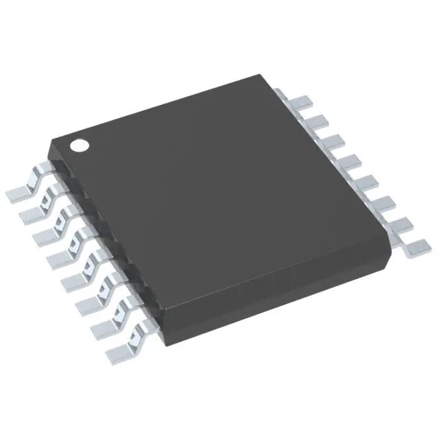
STMicroelectronics LED8102SXTTR
- Part No.:
- LED8102SXTTR
- Manufacturer:
- STMicroelectronics
- Category:
- LED Drivers
- Package:
- 16-TSSOP (0.173", 4.40mm Width) Exposed Pad
- Datasheet:
-
 LED8102SXTTR.pdf
- Description:
- IC LED DRV LIN PWM 16HTSSOP
- Quantity:
- Payment:

- Shipping:

Inventory:781
Please send an inquiry. Send us your inquiry, and we will respond immediately.
Product details
Overview
LED8102SXTTR from STMicroelectronics is an 8-channel low-side constant-current LED driver IC in HTSSOP16 (exposed pad) package, delivering programmable 5–100 mA per channel via external resistor REXT, supporting up to 19 V output headroom and global PWM dimming via OE pin, used for appliance display backlighting and industrial function indicators.
For engineers reviewing the LED8102SXTTR datasheet, LED8102SXTTR pinout, LED8102SXTTR application, or LED8102SXTTR equivalent, key selection criteria include channel-to-channel current matching (±1.2% typ), thermal shutdown at 170 °C with 15 °C hysteresis, and switch-input control logic mapping SW1–SW4 to paired outputs (OUT0/OUT1 through OUT6/OUT7).
Technical Context
The LED8102SXTTR integrates eight independent low-side current sinks with MOSFET-based regulation, each requiring ≥0.85 V headroom for stable 5–100 mA operation and rated for up to 19 V output voltage swing. Its digital control layer uses four dedicated switch inputs (SW1–SW4), each internally pulled down by 300 kΩ, enabling direct TTL/CMOS-compatible ON/OFF control of two-output pairs without address decoding.
Global brightness adjustment is implemented via the OE pin, which accepts PWM signals up to 5.5 V and forces all active channels into synchronous dimming mode; when OE is high, all outputs disable regardless of SWx states. Internal thermal protection disables only output stages-not logic-upon junction temperature exceeding 170 °C, with automatic recovery after 15 °C cooldown.
Key Specifications
| Parameter | Value and Actual Design Meaning |
|---|---|
| Output channels | 8 independent low-side constant-current sinks, each programmable 5–100 mA |
| Output voltage rating | Up to 19 V per channel-supports series strings of white/RGB LEDs |
| Supply voltage range | 3.0 V to 5.5 V-compatible with standard logic rails and USB-powered systems |
| Current setting method | Single external REXT resistor (0.19–3.9 kΩ) sets all channels identically via IOUT = 1.2 V / REXT |
| Channel matching | ±1.2% typical current mismatch between channels at 50 mA, critical for uniform illumination |
| Thermal shutdown | Activates at TJ = 170 °C with 15 °C hysteresis-protects silicon while preserving logic functionality |
| ESD rating | ±2 kV HBM-enables robust handling during PCB assembly and field service |
Pinout & Package
HTSSOP16 package with exposed thermal pad-requires soldering pad to PCB ground plane for effective heat dissipation (Rthj-amb = 37.5 °C/W on JEDEC 2S2P board). Pin 1 is GND; pins 5–12 are output terminals OUT0–OUT7; pin 15 is R-EXT connection point; pin 16 is VDD.
| Pin/Terminal | Circuit Role | Design Meaning |
|---|---|---|
| 1 GND | Ground reference | Common return path for all current sinks and internal logic; must be low-impedance |
| 2 SW1 | Switch input 1 | Controls OUT0 and OUT1 simultaneously; internal 300 kΩ pull-down ensures OFF state if floating |
| 3 SW2 | Switch input 2 | Controls OUT2 and OUT3 simultaneously; compatible with 3.3 V/5 V logic levels |
| 4 SW3 | Switch input 3 | Controls OUT4 and OUT5 simultaneously; no external pull-up required |
| 5–12 OUT0–OUT7 | Low-side current sink outputs | Each delivers regulated current to cathode of connected LED string; open-drain behavior |
| 13 SW4 | Switch input 4 | Controls OUT6 and OUT7 simultaneously; enables full 8-channel local dimming groups |
| 14 OE | Output enable/PWM input | Global dimming control-high = all outputs OFF; low = outputs follow SWx states |
| 15 R-EXT | Current programming node | Connects external resistor to GND to set all channel currents per IOUT = 1.2 V / REXT |
| 16 VDD | Power supply input | Supplies internal logic and current generators; decoupling capacitor required near pin |
Key Features
| Feature | Design Value |
|---|---|
| Direct switch control architecture | Four logic-level inputs (SW1–SW4) directly toggle 2-output pairs-eliminates need for microcontroller GPIO expansion or address decoding |
| Global PWM dimming via OE | OE pin accepts standard PWM signals (0–100% duty cycle) to synchronize brightness across all active channels without timing skew |
| Thermal shutdown with output-only disable | Protects against overtemperature by disabling only current sinks-logic remains operational for fault reporting and recovery sequencing |
| High-voltage output capability | 19 V rated output voltage per channel supports >5 white LEDs in series or mixed-color configurations with forward voltage variation |
| Single-resistor current programming | REXT sets identical current for all 8 channels-reduces BOM count and improves inter-channel consistency vs. per-channel resistors |
Applications
| Appliance Display Backlighting | Industrial Function Indicator |
|---|---|
Use Scenario: Driving segmented white LED arrays behind membrane keypads or LCD overlays in kitchen appliances and HVAC controllers. IC Role / Device Role / Timing Role: Low-side constant-current sink providing stable luminance across varying LED VF and ambient temperature. Use Value: ±1.2% channel matching ensures uniform brightness across display segments without software calibration. | Use Scenario: Illuminating status LEDs on PLC I/O modules, motor drives, and safety-rated panels where visual clarity and long-term reliability are critical. IC Role / Device Role / Timing Role: Direct-switch-controlled LED driver enabling immediate ON/OFF response to hardware fault signals without MCU intervention. Use Value: SWx inputs tolerate floating/unconnected states (default OFF), simplifying wiring in rugged industrial enclosures. |
| Architectural Lighting Zone Control | RGB Color Mixing Module |
Use Scenario: Controlling discrete LED zones in linear cove lighting or signage where grouped dimming replaces complex DMX infrastructure. IC Role / Device Role / Timing Role: Local dimming enabler using SW1–SW4 to define 4 independent zones, each driving 2 parallel LED strings. Use Value: 19 V output headroom accommodates forward voltage drift in aging high-CRI LEDs while maintaining regulation. | Use Scenario: Driving red, green, and blue LED strings in compact color-tunable fixtures where space limits discrete drivers per channel. IC Role / Device Role / Timing Role: Constant-current source for each primary color sub-string, with OE enabling synchronized RGB PWM mixing. Use Value: Single REXT resistor ensures matched current scaling across R/G/B channels-critical for stable white-point maintenance. |
Equivalent & Alternatives
The following parts are listed as comparable options for similar 8-channel LED driver applications.
| Alternative Part | Technical Difference | Application Difference | Selection Advice |
|---|---|---|---|
| TLC59283RTJR | 16-bit PWM dimming per channel; SPI interface; no direct switch inputs | Requires microcontroller for configuration; suited for dynamic color animation, not simple on/off zoning | Select when per-channel PWM resolution >8-bit and serial control are required |
| MAX7219CWG+ | Integrated scan driver + 8×8 matrix control; common-cathode only; 40 V max output | Designed for multiplexed LED matrices-not constant-current string driving | Select only for alphanumeric or icon displays with shared anodes/cathodes |
Compared with TLC59283RTJR and MAX7219CWG+, LED8102SXTTR offers simpler hardware integration for fixed-function local dimming, eliminates firmware dependency, and provides higher per-channel current precision (±1.2% vs. ±3% typical) without serial communication overhead.
Availability
LED8102SXTTR is available at Aetrix Electronics and suitable for appliance display backlighting, industrial function indicators, architectural lighting zone control, and RGB color mixing modules requiring stable component supply and long-lifecycle support.
Supply support for LED8102SXTTR includes scheduled delivery planning, volume procurement assistance, BOM continuity management, traceable sourcing, and lifecycle availability coordination for OEM customers, industrial embedded developers, connected-device designers, and electronics production programs.
Manufacturer
STMicroelectronics is a global semiconductor leader headquartered in Geneva, Switzerland, designing and manufacturing analog, power, microcontroller, and sensor solutions for industrial, automotive, and consumer markets.
The LED8102SXTTR belongs to ST's LED driver product line, engineered specifically for cost-sensitive, high-reliability lighting applications requiring direct hardware control, thermal resilience, and minimal external components.
FAQ
What is the minimum headroom voltage required for stable current regulation?
The LED8102SXTTR requires a minimum output headroom voltage of 0.85 V across each current generator to maintain regulation. At 50 mA output, typical headroom is ~1.4 V; lower headroom causes current droop, while excessive headroom increases power dissipation. The device guarantees regulation up to 19 V output voltage swing.
How does the OE pin interact with the SWx inputs during PWM dimming?
When OE is held low, outputs respond directly to SWx states-enabling local on/off control. When OE receives a PWM signal, all currently enabled outputs (per SWx) are synchronously modulated at the same duty cycle. If OE is high, all outputs force OFF regardless of SWx logic levels-a hardware emergency disable function.
Can unused output channels be left unconnected without affecting performance?
Yes-unused OUT0–OUT7 pins may be left unconnected or tied to GND without impacting regulation accuracy or thermal behavior. The device does not require termination resistors or dummy loads on inactive channels, simplifying layout for partial-channel implementations.
What PCB layout practices maximize thermal performance in HTSSOP16 package?
Solder the exposed thermal pad directly to a large copper pour connected to GND via ≥9 vias (e.g., 3×3 array); use ≥4-layer board with inner power/ground planes; extend copper beyond package footprint; avoid narrow traces on VDD and GND paths. These practices reduce Rthj-amb toward the specified 37.5 °C/W.
LED8102SXTTR Specifications
- Product attributes
- Attribute value
- Manufacturer:
- STMicroelectronics
- Series:
- -
- Package/Case:
- 16-TSSOP (0.173", 4.40mm Width) Exposed Pad
- Packaging:
- Tape & Reel (TR)
- Product Status:
- Active
- Type:
- Linear
- Topology:
- -
- Internal Switch(s):
- Yes
- Number of Outputs:
- 8
- Voltage - Supply (Min):
- 3V
- Voltage - Supply (Max):
- 5.5V
- Voltage - Output:
- 0.85V ~ 19V
- Current - Output / Channel:
- 100mA
- Frequency:
- -
- Dimming:
- PWM
- Applications:
- Backlight, Lighting
- Operating Temperature:
- -40°C ~ 150°C (TJ)
- Grade:
- -
- Qualification:
- -
- Mounting Type:
- Surface Mount
- Supplier Device Package:
- 16-HTSSOP
LED8102SXTTR FAQ
1.How can I place an order for LED8102SXTTR through Aetrix?
Please submit a Request for Quotation (RFQ) for LED8102SXTTR on Aetrix. Our sales agent will provide a competitive quotation and guide you through the order confirmation once you accept the terms.
2.Are the price and stock information for LED8102SXTTR reliable?
The price and inventory of LED8102SXTTR are updated periodically and may fluctuate due to market conditions. Stock and pricing data are typically refreshed every 24 hours. Quotation validity for LED8102SXTTR is usually 5 days.
3.What payment methods are accepted for LED8102SXTTR?
We accept Wire Transfer, PayPal, Credit Card, Western Union, MoneyGram, and Escrow for LED8102SXTTR transactions.
Note: Certain payment methods may incur a processing fee.
4.How is shipping managed for LED8102SXTTR?
LED8102SXTTR orders can be shipped via leading logistics carriers, including DHL, UPS, FedEx, TNT, or Registered Mail.
Once your LED8102SXTTR order is processed, you will receive an email with the shipment details and tracking number.
Note: Tracking information may take up to 24 hours to appear. Express delivery typically takes 3–5 business days.
5.How can I obtain technical support or documentation for LED8102SXTTR?
For technical support, including LED8102SXTTR datasheets, pinout diagrams, or application guidance, please contact our engineering support team. They can provide detailed documentation and assistance for your LED8102SXTTR requirements.
6.How does Aetrix verify that LED8102SXTTR is sourced from the original manufacturer or authorized distributors?
All LED8102SXTTR products on Aetrix are procured from qualified distributors and authorized channels. Our dedicated quality assurance team conducts strict verification, including traceability checks and, if necessary, third-party testing. This ensures that LED8102SXTTR meets industry standards.
7.What is the process for return or replacement of LED8102SXTTR?
All LED8102SXTTR units undergo pre-shipment inspection (PSI). If there is an issue with LED8102SXTTR, returns or replacements are accepted under the following conditions:
1.Quantity discrepancies, incorrect items, or visible external defects (such as breakage or corrosion), acknowledged by Aetrix.
2.The issue is reported within 90 days of delivery.
3.The LED8102SXTTR part is unused and in its original packaging.
Return procedure for LED8102SXTTR:
1.Submit a request within 90 days.
2.Obtain a Return Material Authorization (RMA) from Aetrix.
LED8102SXTTR Tags

-
BCR402RE6327HTSA1
Infineon Technologies

-
BCR430UXTSA2
Infineon Technologies

-
BCR420UE6433HTMA1
Infineon Technologies
-
BCR420UE6327HTSA1
Infineon Technologies
-
BCR421UE6327HTSA1
Infineon Technologies

-
LYT1604D-TL
Power Integrations

-
HV9910CLG-G
Microchip Technology

-
CL2N8-G
Microchip Technology

-
BCR420UW6-7
Diodes Incorporated
-
BCR421UW6-7
Diodes Incorporated

-
BCR420UFD-7
Diodes Incorporated
-
BCR421UFD-7
Diodes Incorporated
Tech Hub

A practical engineering and sourcing framework covering lifecycle verification, lifetime-buy calculations, replacement qualification, supplier checks and counterfeit-risk controls.

TTL and CMOS logic families differ in thresholds, loading, output drive, power and timing. This engineering guide compares 74HC and 74HCT, calculates noise margins and checks 3.3 V/5 V compatibility.

A practical engineering guide to 3.3V and 5V logic compatibility, input thresholds, resistor dividers, translator ICs, MOSFET level shifting, I2C pull-ups, timing limits and power-sequencing risks.

The 74HC595 uses push-pull logic outputs, while the TPIC6B595 uses 50 V open-drain DMOS sinks for higher-power loads. This guide compares timing, current limits, 3.3 V interfacing, load wiring, thermal…

The 74HC595 converts serial data into eight stable parallel outputs. This guide covers pin functions, shift and storage timing, OE and MR behavior, drive-current limits, cascading, voltage compatibilit…

A technical comparison of level-sensitive latches and edge-triggered flip-flops, covering timing windows, setup and hold limits, master–slave operation, time borrowing, race-through, HDL inference and…

A D latch stores one bit while Enable controls when data can pass. This reference covers gate-level operation, truth tables, transparency, setup and hold timing, LE versus OE, common ICs and practical …

An SR latch stores one bit through cross-coupled feedback. This engineering reference covers NOR and NAND implementations, truth tables, forbidden-state recovery, gated operation, switch debouncing, fa…

Latch circuits retain one bit through feedback. This technical reference covers SR and D latches, truth tables, transparency, timing limits, latch-versus-flip-flop behavior, applications and common log…

An engineering guide to LED driver operation, constant-current and constant-voltage outputs, linear and switching topologies, dimming, IC selection, calculations, replacement compatibility, and fault c…


