
 My Inquiry
 My Account


Vishay Semiconductor Opto Division LH1512BAC
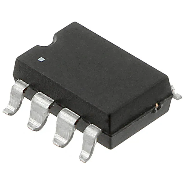
- Part No.:
- LH1512BAC
- Manufacturer:
- Vishay Semiconductor Opto Division
- Category:
- Solid State Relays (SSR)
- Package:
- 8-SMD (0.300", 7.62mm)
- Datasheet:
-
 LH1512BAC.pdf
- Description:
- RELAY SPST-NO/NC 200MA 0-200V
- Quantity:
- Payment:

- Shipping:

Inventory:1,072
Please send an inquiry. Send us your inquiry, and we will respond immediately.
Product details
Overview
LH1512BAC from Vishay Semiconductors is a dual 1 Form A/B, C solid-state relay (SSR) in an SMD-8 package, integrating infrared LED actuation with photodiode-driven MOSFET output switches. It supports independent normally open (NO) and normally closed (NC) operation or combined Form C switching, with 200 V load voltage rating, 200 mA continuous load current, and 10 Ω typical on-resistance - deployed in telecom line interface circuits requiring bounce-free, isolated switching.
For engineers reviewing the LH1512BAC datasheet, LH1512BAC pinout, LH1512BAC application, or LH1512BAC equivalent, this page delivers verified electrical specs, isolation performance (3750 VRMS), thermal derating curves, agency approvals (UL/VDE/CQC/FIMKO), and real-world use context for telecom and industrial control design validation.
Technical Context
The LH1512BAC implements optically isolated control via an integrated infrared LED coupled to a photodiode array that drives dual complementary MOSFETs - enabling simultaneous NO and NC channel operation with independent input control logic. Its hybrid multichip construction ensures galvanic isolation between input and output domains.
Each output channel features built-in current-limit protection (360 mA typical trip), low off-state leakage (<1 μA at ±200 V), and clean transition characteristics (1.4 ms typical turn-on for NO, 2.0 ms for NC). The device operates across –40 °C to +85 °C ambient and supports reflow soldering per J-STD-020 for SMD-8 packaging.
Key Specifications
| Parameter | Value and Actual Design Meaning |
|---|---|
| Load Voltage | 200 V DC or peak AC - supports standard telecom line voltages including ring signal and ground-start circuits. |
| Continuous Load Current | 200 mA per channel - sufficient for driving relays, small solenoids, and analog switch loads in instrumentation interfaces. |
| On-Resistance (RON) | 10 Ω typical - minimizes I²R heating and voltage drop in low-power analog signal path switching. |
| Input-to-Output Isolation | 3750 VRMS - meets reinforced insulation requirements for UL, VDE, and CQC safety certification in end equipment. |
| Turn-On Time (NO) | 1.4 ms typical - enables fast response in dial-pulse decoding and hook-state detection without timing jitter. |
| Current Limit Threshold | 360 mA typical - protects internal MOSFETs during transient surges such as lightning-induced line spikes. |
| Off-State Leakage | <1 μA at ±200 V - ensures high impedance integrity for precision measurement front-ends and fault-sensing circuits. |
Pinout & Package
SMD-8 surface-mount package with gull-wing leads; 7.62 mm × 9.65 mm body, 2.54 mm lead pitch, RoHS-compliant matte tin finish.
| Pin/Terminal | Circuit Role | Design Meaning |
|---|---|---|
| 1, 2 | LED Anode / Cathode | Optical input control: forward current ≥0.6 mA activates NO channel; ≥0.9 mA activates NC channel. |
| 5, 6 | Form A Output (S1, S1′) | Normally open switch terminals - conduct when LED is energized; rated 200 V/200 mA. |
| 7, 8 | Form B Output (S2, S2′) | Normally closed switch terminals - open when LED is energized; shares same isolation barrier as Form A. |
| 3, 4 | Common Reference / NC Tie | Internal connection point for shared source/drain nodes; not externally accessible in standard operation. |
Key Features
| Feature | Design Value |
|---|---|
| Clean bounce-free switching | Zero mechanical contact wear or arcing - eliminates signal chatter in sensitive analog sampling paths. |
| Integrated current limit protection | Self-regulating MOSFET gate drive limits peak current to ~360 mA, preventing latch-up during surge events. |
| Dual independent channel topology | Enables single-device implementation of Form C (SPDT) function without external logic or cross-coupling. |
| Low power LED drive requirement | NO channel activation at just 0.6 mA typical IF - compatible with microcontroller GPIOs without buffer stages. |
| High pole-to-pole isolation | 1600 V isolation between S1–S2 outputs - prevents crosstalk in differential or dual-rail switching applications. |
Applications
| Telecom Line Interface | Industrial Analog Signal Routing |
|---|---|
Use Scenario: On/off hook detection and ring delay timing in PSTN line cards. IC Role / Device Role / Timing Role: Solid-state relay providing isolated, low-leakage switching between line feed circuitry and codec interface. Use Value: Eliminates mechanical relay wear while maintaining <1 μA off-state leakage critical for accurate loop-current sensing. |
Use Scenario: Multiplexing sensor inputs to ADC channels in programmable logic controllers. IC Role / Device Role / Timing Role: Dual-channel analog switch isolating high-voltage field signals from low-voltage measurement subsystems. Use Value: 3750 VRMS isolation and 10 Ω RON enable safe, low-distortion signal routing without level-shifting circuitry. |
| Ground Fault Protection Circuit | Test Equipment Signal Path Control |
Use Scenario: Monitoring continuity between chassis ground and telecom line shield in safety-critical infrastructure. IC Role / Device Role / Timing Role: Normally closed (NC) channel used as fail-safe monitor path; opens only during fault condition. Use Value: 200 mA NC current rating supports direct integration into fault-detection comparators without external amplification. |
Use Scenario: Automated test fixture sequencing where DUT signal paths must be reconfigured under software control. IC Role / Device Role / Timing Role: Form C SSR acting as SPDT selector for calibration reference vs. DUT signal routing. Use Value: Sub-3 ms switching time and zero contact bounce ensure precise timing alignment in high-speed automated test sequences. |
Equivalent & Alternatives
The following parts are listed as comparable options for similar solid-state relay applications.
| Alternative Part | Technical Difference | Application Difference | Selection Advice |
|---|---|---|---|
| Vishay LH1512BACTR | Identical die and electrical specs; differs only in tape-and-reel packaging (vs. tube for LH1512BAC). | No functional difference - selected for automated SMT assembly rather than manual or low-volume placement. | Choose LH1512BACTR for pick-and-place production; LH1512BAC for prototyping or repair stock. |
| Vishay LH1512BB | DIP-8 through-hole package; identical electrical performance but larger footprint and different thermal profile. | Used where board-level serviceability, hand-soldering, or legacy DIP layout compatibility is required. | Select LH1512BB for through-hole designs or environments requiring higher mechanical robustness under vibration. |
Compared with LH1512BACTR (tape-and-reel variant) and LH1512BB (DIP-8 variant), the LH1512BAC offers identical SSR functionality in SMD-8 tube packaging - making it optimal for low-volume builds, engineering validation, and replacement scenarios where reel logistics are unnecessary.
Availability
LH1512BAC is available at Aetrix Electronics and suitable for telecom line interface, industrial analog signal routing, ground fault protection, and automated test equipment requiring stable component supply, long-term lifecycle support, and certified safety isolation.
Supply support for LH1512BAC includes scheduled delivery planning, volume procurement assistance, BOM continuity management, traceable sourcing, and lifecycle availability coordination for OEM customers, industrial embedded developers, connected-device designers, and electronics production programs.
Manufacturer
Vishay Semiconductors is a global leader in discrete semiconductors and passive components, specializing in high-reliability optoelectronics, power management, and sensing solutions for industrial and telecom markets.
The LH1512BAC belongs to Vishay's LH15xx series of dual-form solid-state relays, engineered specifically for replacing electromechanical relays in telecom infrastructure, instrumentation, and safety-critical control systems where longevity and isolation integrity are mandatory.
FAQ
What is the maximum load voltage rating for the LH1512BAC?
The LH1512BAC supports up to 200 V DC or peak AC load voltage across both its Form A (NO) and Form B (NC) output channels. This rating is validated per absolute maximum specifications and applies under continuous operation at ambient temperatures up to +85 °C, with derating required above that temperature per Figure 1 in the datasheet.
Does the LH1512BAC require external current limiting for its LED input?
No - the LH1512BAC does not require external series resistors for LED current limiting in most applications because its input LED has a typical forward voltage of 1.26 V at 10 mA, and the device activates reliably at just 0.6 mA (NO) or 0.9 mA (NC). However, a current-limiting resistor is still recommended to ensure stable IF control and prevent overdrive under varying supply conditions.
Can the LH1512BAC be used as a true Form C (SPDT) relay?
Yes - the LH1512BAC integrates independent Form A (pins 5–6) and Form B (pins 7–8) outputs sharing a common reference structure, allowing it to function as a single-pole double-throw (SPDT) solid-state relay. When used together with appropriate external wiring, it provides break-before-make or make-before-break behavior depending on control timing, as confirmed in the device description and switching timing data.
What safety certifications does the LH1512BAC hold?
The LH1512BAC is certified by UL, VDE, CQC, and FIMKO for input-to-output isolation up to 3750 VRMS. These approvals validate its suitability for reinforced insulation in end equipment meeting IEC/EN 60950-1 and IEC/EN 62368-1 standards, particularly in telecom and industrial control applications where user and system safety are critical.
How does the current limit protection operate in the LH1512BAC?
The LH1512BAC incorporates internal current-limit circuitry that clamps peak load current to approximately 360 mA (typical) during transient overloads. This feature acts autonomously on each output channel without external components and prevents destructive thermal runaway in the MOSFET output stage - verified in the Electrical Characteristics table under "Current limit: (NO)" parameter.
LH1512BAC Specifications
- Product attributes
- Attribute value
- Manufacturer:
- Vishay Semiconductor Opto Division
- Series:
- LH1512
- Packaging:
- Tube
- Product Status:
- Active
- Mounting Type:
- Surface Mount
- Circuit:
- SPST-NO + SPST-NC (1 Form A and B)
- Output Type:
- AC, DC
- Voltage - Input:
- 1.26VDC
- Voltage - Load:
- 0 V ~ 200 V
- Load Current:
- 200 mA
- On-State Resistance (Max):
- 10 Ohms
- Termination Style:
- Gull Wing
- Operating Temperature:
- -40°C ~ 85°C
- Supplier Device Package:
- 8-SMD
- Approval Agency:
- CQC, FIMKO, UL, VDE
- Grade:
- -
- Qualification:
- -
LH1512BAC FAQ
1.How can I place an order for LH1512BAC through Aetrix?
Please submit a Request for Quotation (RFQ) for LH1512BAC on Aetrix. Our sales agent will provide a competitive quotation and guide you through the order confirmation once you accept the terms.
2.Are the price and stock information for LH1512BAC reliable?
The price and inventory of LH1512BAC are updated periodically and may fluctuate due to market conditions. Stock and pricing data are typically refreshed every 24 hours. Quotation validity for LH1512BAC is usually 5 days.
3.What payment methods are accepted for LH1512BAC?
We accept Wire Transfer, PayPal, Credit Card, Western Union, MoneyGram, and Escrow for LH1512BAC transactions.
Note: Certain payment methods may incur a processing fee.
4.How is shipping managed for LH1512BAC?
LH1512BAC orders can be shipped via leading logistics carriers, including DHL, UPS, FedEx, TNT, or Registered Mail.
Once your LH1512BAC order is processed, you will receive an email with the shipment details and tracking number.
Note: Tracking information may take up to 24 hours to appear. Express delivery typically takes 3–5 business days.
5.How can I obtain technical support or documentation for LH1512BAC?
For technical support, including LH1512BAC datasheets, pinout diagrams, or application guidance, please contact our engineering support team. They can provide detailed documentation and assistance for your LH1512BAC requirements.
6.How does Aetrix verify that LH1512BAC is sourced from the original manufacturer or authorized distributors?
All LH1512BAC products on Aetrix are procured from qualified distributors and authorized channels. Our dedicated quality assurance team conducts strict verification, including traceability checks and, if necessary, third-party testing. This ensures that LH1512BAC meets industry standards.
7.What is the process for return or replacement of LH1512BAC?
All LH1512BAC units undergo pre-shipment inspection (PSI). If there is an issue with LH1512BAC, returns or replacements are accepted under the following conditions:
1.Quantity discrepancies, incorrect items, or visible external defects (such as breakage or corrosion), acknowledged by Aetrix.
2.The issue is reported within 90 days of delivery.
3.The LH1512BAC part is unused and in its original packaging.
Return procedure for LH1512BAC:
1.Submit a request within 90 days.
2.Obtain a Return Material Authorization (RMA) from Aetrix.
LH1512BAC Tags
.jpg)
-
G3VM-21UR11(TR05)
Omron Electronics Inc-EMC Div
-
G3VM-61VY3(TR05)
Omron Electronics Inc-EMC Div
-
CPC1017NTR
Littelfuse Inc.
-
CPC1017N
Littelfuse Inc.
-
CPC1006N
Littelfuse Inc.
-
VO1400AEFTR
Vishay Semiconductor Opto Division
-
CPC1006NTR
Littelfuse Inc.
-
TLP175A(TPL,E
Toshiba Semiconductor and Storage
-
CPC1002NTR
Littelfuse Inc.
-
AQY280S
Panasonic Electric Works
-
CPC1117NTR
Littelfuse Inc.
-
CPC1106NTR
Littelfuse Inc.
Tech Hub

Counterfeit components can hide behind convincing markings and passing basic function tests. This engineering reference covers source traceability, external inspection, X-ray, XRF, electrical testing, …

A practical engineering and sourcing framework covering lifecycle verification, lifetime-buy calculations, replacement qualification, supplier checks and counterfeit-risk controls.

TTL and CMOS logic families differ in thresholds, loading, output drive, power and timing. This engineering guide compares 74HC and 74HCT, calculates noise margins and checks 3.3 V/5 V compatibility.

A practical engineering guide to 3.3V and 5V logic compatibility, input thresholds, resistor dividers, translator ICs, MOSFET level shifting, I2C pull-ups, timing limits and power-sequencing risks.

The 74HC595 uses push-pull logic outputs, while the TPIC6B595 uses 50 V open-drain DMOS sinks for higher-power loads. This guide compares timing, current limits, 3.3 V interfacing, load wiring, thermal…

The 74HC595 converts serial data into eight stable parallel outputs. This guide covers pin functions, shift and storage timing, OE and MR behavior, drive-current limits, cascading, voltage compatibilit…

A technical comparison of level-sensitive latches and edge-triggered flip-flops, covering timing windows, setup and hold limits, master–slave operation, time borrowing, race-through, HDL inference and…

A D latch stores one bit while Enable controls when data can pass. This reference covers gate-level operation, truth tables, transparency, setup and hold timing, LE versus OE, common ICs and practical …

An SR latch stores one bit through cross-coupled feedback. This engineering reference covers NOR and NAND implementations, truth tables, forbidden-state recovery, gated operation, switch debouncing, fa…

Latch circuits retain one bit through feedback. This technical reference covers SR and D latches, truth tables, transparency, timing limits, latch-versus-flip-flop behavior, applications and common log…


