
 My Inquiry
 My Account


Vishay Semiconductor Opto Division LH1535AT
- Part No.:
- LH1535AT
- Manufacturer:
- Vishay Semiconductor Opto Division
- Category:
- Solid State Relays (SSR)
- Package:
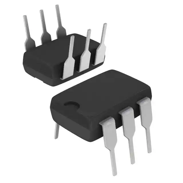
- 6-DIP (0.300", 7.62mm)
- Datasheet:
-
 LH1535AT.pdf
- Description:
- SSR RELAY SPST-NO 120MA 0-400V
- Quantity:
- Payment:

- Shipping:

Inventory:3,935
Please send an inquiry. Send us your inquiry, and we will respond immediately.
Product details
Overview
LH1535AT from Vishay Semiconductors is a DIP-6 packaged solid-state relay (Form A, SPST NO) combining a GaAlAs LED input and monolithic high-voltage dielectrically isolated MOSFET output stage. It delivers 400 V load voltage rating, 120 mA continuous bidirectional load current, 20 Ω typical on-resistance, and 5300 VRMS input-output isolation - enabling replacement of electromechanical relays in telecom line card protection and ground fault detection circuits.
For engineers reviewing the LH1535AT datasheet, LH1535AT pinout, LH1535AT application, or LH1535AT equivalent, this device requires attention to its current-limiting architecture (210 mA typical ILMT), temperature-dependent turn-on/off timing (0.7–2 ms), and safety-certified creepage/clearance (≥7 mm) for IEC 68-1 climatic class 40/85/21 industrial deployments.
Technical Context
The LH1535AT integrates photodiode array actuation, switch control logic, and dual MOSFETs in a single die with dielectric isolation - enabling clean bounce-free switching and inherent current limiting per FCC 68.302 surge requirements when external overvoltage protection is applied. Its output stage supports bidirectional AC/DC loads up to 400 V with ≤0.4 V switch offset and <200 nA off-state leakage at ±100 V.
Input drive is optimized for low-power LED activation: turn-on threshold as low as 0.75 mA (typ.) at 10 ms pulse, with forward voltage of 1.27 V (typ.) at 10 mA. The device operates across –40 °C to +85 °C ambient and maintains ≥10⁹ Ω insulation resistance at storage temperature (150 °C).
Key Specifications
| Parameter | Value and Actual Design Meaning |
|---|---|
| Load Voltage | 400 V - supports telecom line interface protection and AC mains-sensing applications without external voltage clamping. |
| Continuous Load Current | 120 mA bidirectional - sufficient for driving telecom ring generators, sensor bias networks, and PLC I/O modules. |
| On-Resistance | 20 Ω typical (AC/DC, 50 mA load) - ensures <1 V drop at rated current, minimizing self-heating and power loss. |
| Isolation Voltage | 5300 VRMS - certified to UL1577 (E52744), CSA, and FIMKO for reinforced insulation in safety-critical systems. |
| Current Limit Threshold | 210 mA typical (±6 V, 5 ms pulse) - provides intrinsic short-circuit protection without external sensing circuitry. |
| Turn-on/Off Time | 0.7–2 ms each - enables precise timing control in automated test equipment and programmable logic controller outputs. |
| Creepage & Clearance | ≥7 mm - meets IEC 60664-1 Pollution Degree 2 requirements for industrial PCB layouts with minimal spacing constraints. |
Pinout & Package
DIP-6 package (7.62 mm lead pitch, 8.7 × 6.5 mm body) with through-hole mounting; RoHS-compliant, lead-free finish.
| Pin/Terminal | Circuit Role | Design Meaning |
|---|---|---|
| 1 | LED Anode | Input control terminal requiring 0.75–2 mA for reliable turn-on; connects to microcontroller GPIO or logic driver. |
| 2 | LED Cathode | Ground reference for LED drive; reverse voltage limited to 8 V absolute maximum. |
| 3 | Output Source (S) | High-side switch terminal; connects to load return path in unidirectional configurations. |
| 4 | Output Drain (S′) | Main load current path; ties to 400 V rail or AC line in telecom isolation applications. |
| 5 | Current Limit Sense | Enables internal current limiting when connected between pins 4 and 6; required for FCC 68.302 compliance. |
| 6 | Current Limit Return | Reference node for current limit circuit; must be tied to pin 5 via external trace or zero-ohm resistor. |
Key Features
| Feature | Design Value |
|---|---|
| Dielectrically Isolated MOSFET Output | Eliminates latch-up risk and enables safe operation in mixed-signal systems with shared ground domains. |
| Integrated Current-Limit Circuitry | Reduces need for external fusing or current-sense amplifiers in telecom line interface protection designs. |
| Bounce-Free Switching | Prevents contact chatter artifacts in precision instrumentation sampling and data acquisition trigger paths. |
| Low Power LED Drive | Enables direct interfacing with 3.3 V or 5 V MCU I/O without series resistors exceeding 2 kΩ. |
| UL/CSA/FIMKO Certified | Validates suitability for field-deployed telecom infrastructure and industrial control panels without additional safety testing. |
Applications
| Telecom Line Card Protection | Industrial Ground Fault Detection |
|---|---|
|
Use Scenario: Protecting DSLAM line cards from lightning-induced surges and tip-ring polarity reversals. IC Role / Device Role / Timing Role: Solid-state relay isolating subscriber line interface circuitry from central office switching fabric. Use Value: 5300 VRMS isolation and 400 V load voltage withstand prevent damage during ±2 kV surge events per GR-1089-CORE. |
Use Scenario: Monitoring earth leakage current in motor control cabinets and HVAC variable-frequency drives. IC Role / Device Role / Timing Role: Bidirectional AC/DC switch enabling galvanically isolated sense-path activation in Class I equipment. Use Value: 120 mA continuous current and <200 nA off-state leakage ensure stable baseline readings under 230 VAC nominal conditions. |
| Programmable Logic Controller Outputs | Automated Test Equipment Signal Routing |
|
Use Scenario: Driving solenoid valves and indicator lamps in factory-floor PLC I/O modules. IC Role / Device Role / Timing Role: Form A SPST NO switch replacing mechanical relays for >10⁷ cycle lifetime and silent operation. Use Value: 0.7–2 ms switching time allows synchronized actuation across 16-channel I/O banks without skew compensation. |
Use Scenario: Routing analog stimulus signals between DUT and measurement instruments in ATE rack systems. IC Role / Device Role / Timing Role: Low-capacitance (<22 pF) signal path switch minimizing insertion loss below 100 kHz. Use Value: 21.6 pF output capacitance at 1 V and <0.4 V switch offset preserve signal fidelity for mV-level sensor calibration. |
Equivalent & Alternatives
The following parts are listed as comparable options for similar solid-state relay applications.
| Alternative Part | Technical Difference | Application Difference | Selection Advice |
|---|---|---|---|
| Vishay VO3120 | DIP-6, 400 V/120 mA, but no integrated current limiting; requires external ILMT circuit. | Lacks FCC 68.302 compliance out-of-box; suitable only where surge immunity is handled externally. | Choose VO3120 only if board space permits adding discrete current-sense resistor and comparator. |
| IXYS CPC1976Y | SMD-6, 600 V/100 mA, higher isolation (7500 VRMS), but slower turn-off (3.5 ms max). | Better suited for high-voltage DC battery disconnects than telecom AC line switching. | Select CPC1976Y when >600 V standoff or SMD assembly is mandatory, accepting longer off-time latency. |
Compared with LH1535AT, VO3120 lacks built-in current limiting and requires external components for FCC compliance, while CPC1976Y trades faster switching for higher voltage rating and surface-mount compatibility - making LH1535AT optimal for cost-sensitive, through-hole telecom relay replacements needing integrated surge protection.
Availability
LH1535AT is available at Aetrix Electronics and suitable for telecom infrastructure upgrades, industrial ground fault monitors, and PLC output modules requiring stable component supply with full safety certification traceability.
Supply support for LH1535AT includes scheduled delivery planning, volume procurement assistance, BOM continuity management, traceable sourcing, and lifecycle availability coordination for OEM customers, industrial embedded developers, connected-device designers, and electronics production programs.
Manufacturer
Vishay Intertechnology is a global semiconductor manufacturer specializing in discrete components, optoelectronics, and passive devices with emphasis on reliability and safety certification.
The LH1535AT belongs to Vishay's LH-series solid-state relay family, engineered specifically for telecom line interface protection and industrial isolation applications demanding regulatory-compliant, bounce-free switching without mechanical wear.
FAQ
What is the maximum continuous load current rating for the LH1535AT?
The LH1535AT supports 120 mA continuous bidirectional load current and 250 mA unidirectional current. This rating applies at ambient temperatures up to +85 °C with adequate PCB copper area for thermal dissipation. Exceeding 120 mA in AC or bidirectional DC operation risks thermal runaway due to RON increase above 25 °C - always verify derating curves in Figure 4 of the LH1535AT datasheet (Rev. 1.6, p.4).
Does the LH1535AT require external components to meet FCC 68.302 surge requirements?
Yes - the LH1535AT's internal current-limiting circuitry meets FCC 68.302 only when pins 4 (S′) and 6 (ILMT return) are connected externally, forming a closed current-sense loop. Without this connection, the device lacks surge-rated current limiting. Vishay Application Note AN56 ("Solid State Relays") specifies exact trace routing and layout practices to maintain compliance.
What is the minimum LED forward current needed to reliably turn on the LH1535AT?
The LH1535AT turns on with as little as 0.75 mA (typical) LED forward current at 10 ms pulse width, per electrical characteristics table (p.2). For robust operation across –40 °C to +85 °C, design for 2 mA minimum drive - confirmed by Figure 18 showing <150% relative turn-on current variation over temperature.
Can the LH1535AT switch AC waveforms, and what is its maximum frequency capability?
Yes - the LH1535AT supports bidirectional AC loads up to 400 V peak. Its 21.6 pF output capacitance and 0.7–2 ms switching times limit usable frequency to ≤1 kHz for clean zero-crossing switching. Insertion loss remains <0.25 dB below 10 kHz (Fig. 12), but harmonic distortion rises above 500 Hz due to finite RON nonlinearity - verify with actual load in LH1535AT application circuits.
How does the LH1535AT's isolation performance compare to mechanical relays in harsh environments?
The LH1535AT provides 5300 VRMS isolation with ≥7 mm creepage/clearance and 10¹² Ω insulation resistance at 25 °C - exceeding typical electromechanical relays rated for 3000–4000 VRMS. Its dielectric isolation eliminates contact oxidation and humidity-induced leakage, maintaining performance in 85 °C/85% RH environments (IEC 60068-2-78) where mechanical contacts degrade rapidly.
LH1535AT Specifications
- Product attributes
- Attribute value
- Manufacturer:
- Vishay Semiconductor Opto Division
- Series:
- LH1535
- Packaging:
- Tube
- Product Status:
- Obsolete
- Mounting Type:
- Through Hole
- Circuit:
- SPST-NO (1 Form A)
- Output Type:
- AC, DC
- Voltage - Input:
- 1.27VDC
- Voltage - Load:
- 0 V ~ 400 V
- Load Current:
- 120 mA
- On-State Resistance (Max):
- 20 Ohms
- Termination Style:
- PC Pin
- Operating Temperature:
- -40°C ~ 85°C
- Supplier Device Package:
- 6-DIP
- Approval Agency:
- CSA, FIMKO, UL
- Grade:
- -
- Qualification:
- -
LH1535AT FAQ
1.How can I place an order for LH1535AT through Aetrix?
Please submit a Request for Quotation (RFQ) for LH1535AT on Aetrix. Our sales agent will provide a competitive quotation and guide you through the order confirmation once you accept the terms.
2.Are the price and stock information for LH1535AT reliable?
The price and inventory of LH1535AT are updated periodically and may fluctuate due to market conditions. Stock and pricing data are typically refreshed every 24 hours. Quotation validity for LH1535AT is usually 5 days.
3.What payment methods are accepted for LH1535AT?
We accept Wire Transfer, PayPal, Credit Card, Western Union, MoneyGram, and Escrow for LH1535AT transactions.
Note: Certain payment methods may incur a processing fee.
4.How is shipping managed for LH1535AT?
LH1535AT orders can be shipped via leading logistics carriers, including DHL, UPS, FedEx, TNT, or Registered Mail.
Once your LH1535AT order is processed, you will receive an email with the shipment details and tracking number.
Note: Tracking information may take up to 24 hours to appear. Express delivery typically takes 3–5 business days.
5.How can I obtain technical support or documentation for LH1535AT?
For technical support, including LH1535AT datasheets, pinout diagrams, or application guidance, please contact our engineering support team. They can provide detailed documentation and assistance for your LH1535AT requirements.
6.How does Aetrix verify that LH1535AT is sourced from the original manufacturer or authorized distributors?
All LH1535AT products on Aetrix are procured from qualified distributors and authorized channels. Our dedicated quality assurance team conducts strict verification, including traceability checks and, if necessary, third-party testing. This ensures that LH1535AT meets industry standards.
7.What is the process for return or replacement of LH1535AT?
All LH1535AT units undergo pre-shipment inspection (PSI). If there is an issue with LH1535AT, returns or replacements are accepted under the following conditions:
1.Quantity discrepancies, incorrect items, or visible external defects (such as breakage or corrosion), acknowledged by Aetrix.
2.The issue is reported within 90 days of delivery.
3.The LH1535AT part is unused and in its original packaging.
Return procedure for LH1535AT:
1.Submit a request within 90 days.
2.Obtain a Return Material Authorization (RMA) from Aetrix.
LH1535AT Tags
.jpg)
-
G3VM-21UR11(TR05)
Omron Electronics Inc-EMC Div
-
G3VM-61VY3(TR05)
Omron Electronics Inc-EMC Div
-
CPC1017NTR
Littelfuse Inc.
-
CPC1017N
Littelfuse Inc.
-
CPC1006N
Littelfuse Inc.
-
VO1400AEFTR
Vishay Semiconductor Opto Division
-
CPC1006NTR
Littelfuse Inc.
-
TLP175A(TPL,E
Toshiba Semiconductor and Storage
-
CPC1002NTR
Littelfuse Inc.
-
AQY280S
Panasonic Electric Works
-
CPC1117NTR
Littelfuse Inc.
-
CPC1106NTR
Littelfuse Inc.
Tech Hub

Counterfeit components can hide behind convincing markings and passing basic function tests. This engineering reference covers source traceability, external inspection, X-ray, XRF, electrical testing, …

A practical engineering and sourcing framework covering lifecycle verification, lifetime-buy calculations, replacement qualification, supplier checks and counterfeit-risk controls.

TTL and CMOS logic families differ in thresholds, loading, output drive, power and timing. This engineering guide compares 74HC and 74HCT, calculates noise margins and checks 3.3 V/5 V compatibility.

A practical engineering guide to 3.3V and 5V logic compatibility, input thresholds, resistor dividers, translator ICs, MOSFET level shifting, I2C pull-ups, timing limits and power-sequencing risks.

The 74HC595 uses push-pull logic outputs, while the TPIC6B595 uses 50 V open-drain DMOS sinks for higher-power loads. This guide compares timing, current limits, 3.3 V interfacing, load wiring, thermal…

The 74HC595 converts serial data into eight stable parallel outputs. This guide covers pin functions, shift and storage timing, OE and MR behavior, drive-current limits, cascading, voltage compatibilit…

A technical comparison of level-sensitive latches and edge-triggered flip-flops, covering timing windows, setup and hold limits, master–slave operation, time borrowing, race-through, HDL inference and…

A D latch stores one bit while Enable controls when data can pass. This reference covers gate-level operation, truth tables, transparency, setup and hold timing, LE versus OE, common ICs and practical …

An SR latch stores one bit through cross-coupled feedback. This engineering reference covers NOR and NAND implementations, truth tables, forbidden-state recovery, gated operation, switch debouncing, fa…

Latch circuits retain one bit through feedback. This technical reference covers SR and D latches, truth tables, transparency, timing limits, latch-versus-flip-flop behavior, applications and common log…


