
 My Inquiry
 My Account


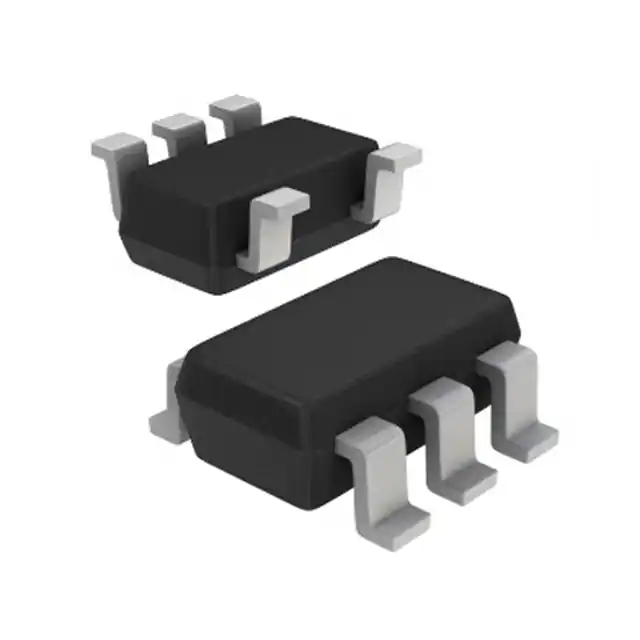
STMicroelectronics LIS3MDLTR
.jpg)
- Part No.:
- LIS3MDLTR
- Manufacturer:
- STMicroelectronics
- Category:
- Linear, Compass (ICs)
- Package:
- 12-VFLGA
- Datasheet:
-
 LIS3MDLTR.pdf
- Description:
- SENSOR MR I2C/SPI 12LGA
- Quantity:
- Payment:

- Shipping:

Inventory:18,396
Please send an inquiry. Send us your inquiry, and we will respond immediately.
Product details
Overview
LIS3MDLTR from STMicroelectronics is an ultralow-power, high-performance 3-axis digital magnetometer IC with user-selectable full-scale ranges of ±4/±8/±12/±16 gauss, 16-bit output resolution, I²C/SPI dual-interface support, and integrated self-test functionality. It operates from 1.9 V to 3.6 V supply voltage with independent 1.8 V I/O rail and delivers RMS noise as low as 3.2 mgauss in ultrahigh-performance mode - enabling precision electronic compassing in handheld navigation devices.
For engineers reviewing the LIS3MDLTR datasheet, LIS3MDLTR pinout, LIS3MDLTR application, or LIS3MDLTR equivalent, key selection criteria include magnetic sensitivity (6842 LSB/gauss at ±4 G), zero-gauss offset stability (±1 gauss), interrupt-driven field detection, low-power operation (40 µA in LP mode), and LGA-12L package compatibility with space-constrained PCB layouts.
Technical Context
The LIS3MDLTR integrates a triaxial anisotropic magnetoresistive (AMR) sensing element with on-chip signal conditioning, 16-bit sigma-delta ADC, and programmable gain amplifier. Its factory-trimmed sensitivity and zero-gauss offset are stored in nonvolatile memory and auto-loaded at power-up, eliminating need for system-level calibration.
It supports two serial interfaces via shared pins: I²C (100 kHz / 400 kHz) with configurable slave address (0x38/0x3C or 0x39/0x3D), and SPI in 3-wire or 4-wire mode controlled by CS and SIM bit. Interrupt generation (INT) and data-ready (DRDY) signals enable event-driven firmware architectures without polling overhead.
Key Specifications
| Parameter | Value and Actual Design Meaning |
|---|---|
| Supply Voltage | 1.9 V to 3.6 V core; 1.71 V to 1.8 V I/O - enables direct interfacing with 1.8 V logic while maintaining robust analog performance |
| Full-Scale Range | ±4/±8/±12/±16 gauss - selectable via CTRL_REG2 register to optimize resolution vs. dynamic range for compass or current-sensing use |
| Sensitivity | 6842 LSB/gauss (±4 G); 1711 LSB/gauss (±16 G) - determines minimum detectable field change (e.g., 0.146 µT/LSB at ±4 G) |
| RMS Noise | 3.2 mgauss (X/Y-axis, ±12 G, ultrahigh-performance mode) - defines heading accuracy limit in Earth's ~500 mG field |
| Current Consumption | 40 µA (low-power mode, 20 Hz ODR); 270 µA (ultrahigh-resolution mode) - enables multi-year battery life in wearable compass applications |
| Operating Temperature | −40 °C to +85 °C - qualified for automotive cabin, industrial handheld, and outdoor consumer electronics environments |
| Interface Support | I²C fast-mode (400 kHz) and SPI up to 10 MHz - allows real-time streaming of 3-axis magnetic data at ≥100 Hz without bus contention |
Pinout & Package
The LIS3MDLTR is housed in a 2 mm × 2 mm × 0.7 mm LGA-12L (land grid array) package with exposed pad for thermal and electrical grounding. Pin numbering follows top-view orientation per DS9463 Rev 7.
| Pin/Terminal | Circuit Role | Design Meaning |
|---|---|---|
| 1 SCL/SPC | I²C clock / SPI clock | Shared bidirectional clock input; requires external pull-up for I²C; driven by master in SPI |
| 2 Reserved | No connect | Must be connected to GND per datasheet - floating violates ECOPACK compliance and may induce noise |
| 3 GND | Analog/digital ground | Primary reference for internal ADC and sensor bias; must be low-impedance connection to system ground plane |
| 4 C1 | Capacitor terminal | Connects to 100 nF decoupling capacitor - stabilizes internal bias circuitry and reduces measurement drift |
| 5 Vdd | Core supply | Provides power to magnetic sensing element and analog front-end; requires 100 nF ceramic decoupling |
| 6 Vdd_IO | I/O supply | Supplies 1.8 V logic interface; powers SDA/SDI/SDO/SCL/SPC/CS/INT/DRDY pins independently of core voltage |
| 7 INT | Interrupt output | Open-drain active-low signal triggered by magnetic threshold crossing, data ready, or self-test completion |
| 8 DRDY | Data-ready indicator | Asserts when new 3-axis sample is available in output registers - eliminates need for polling in low-power firmware |
| 9 SDO/SA1 | SPI output / I²C address bit | In I²C mode: sets LSB of slave address (0x38/0x39 or 0x3C/0x3D); in SPI mode: serial data output |
| 10 CS | SPI enable / I²C disable | Low = SPI active; High = I²C enabled - selects communication protocol without hardware rework |
| 11 SDA/SDI/SDO | I²C data / SPI input-output | Bidirectional I²C data line; SPI input (SDI) or output (SDO) depending on RW bit - shared pin reduces PCB routing complexity |
| 12 Reserved | No connect | Must be connected to GND - ensures mechanical stability and EMI shielding integrity of LGA package |
Key Features
| Feature | Design Value |
|---|---|
| Factory-calibrated sensitivity & zero-gauss offset | Trimming parameters stored in nonvolatile memory and auto-loaded at boot - removes requirement for host MCU calibration routines |
| Programmable interrupt generator | Configurable thresholds, latching behavior, and source selection (magnetic event, data ready, self-test) - enables autonomous sensor wake-up |
| Dual serial interface (I²C/SPI) | Shared pin mapping with software-selectable protocol - supports legacy I²C designs and high-speed SPI data acquisition on same BOM |
| Ultralow-power operation modes | Power-down (1 µA), low-power (40 µA), and ultrahigh-resolution (270 µA) - allows dynamic trade-off between accuracy and battery runtime |
| Integrated self-test | Electromagnetically induced test field applied to each axis - verifies sensor functionality and signal chain integrity in final assembly |
Applications
| Smartphone Electronic Compass | Industrial Current Sensing |
|---|---|
|
Use Scenario: Real-time heading calculation in mobile navigation apps using Earth's geomagnetic field. IC Role / Device Role / Timing Role: Primary 3-axis magnetic field transducer; outputs calibrated 16-bit XYZ samples at 20–100 Hz ODR. Use Value: ±1 gauss zero-gauss offset and 3.2 mgauss RMS noise ensure <2° heading error under typical indoor conditions with no host calibration. |
Use Scenario: Non-invasive DC/AC current monitoring in motor drives via magnetic field around conductor traces. IC Role / Device Role / Timing Role: High-sensitivity field detector placed near current-carrying trace; configured for ±4 gauss full scale. Use Value: 6842 LSB/gauss sensitivity enables resolution of <150 mA current changes in 1 mm trace spacing - sufficient for fault detection. |
| Wearable Fitness Tracker | Automotive Cabin Position Sensing |
|
Use Scenario: Step counting and activity classification using orientation-aware motion fusion with accelerometer. IC Role / Device Role / Timing Role: Magnetometer in 9-DoF IMU subsystem; synchronized sampling with LIS2DH12/LIS2DE12 via DRDY handshake. Use Value: 40 µA low-power mode extends coin-cell battery life to >12 months while maintaining compass-grade accuracy during periodic wake-ups. |
Use Scenario: Detection of seatbelt buckle presence or door/window open/closed state via ferrous metal proximity. IC Role / Device Role / Timing Role: Static-field threshold detector; INT pin triggers MCU only on magnetic transition events. Use Value: Programmable interrupt with 50 gauss magnetic disturbance immunity prevents false triggers from nearby speakers or actuators. |
Equivalent & Alternatives
The following parts are listed as comparable options for similar 3-axis magnetometer applications.
| Alternative Part | Technical Difference | Application Difference | Selection Advice |
|---|---|---|---|
| AK09918C | Higher sensitivity (8000 LSB/G at ±4 G), but no self-test; I²C-only interface; 1.71–1.98 V I/O range | Lacks interrupt flexibility and SPI option; requires tighter I/O voltage control | Preferred where maximum resolution is critical and I²C-only architecture is fixed |
| BMM150 | Lower power (20 µA LP mode), but higher noise (5.5 mgauss); ±1300 µT max range; no factory calibration storage | Requires host-side calibration; less suitable for precision compassing in variable thermal environments | Selected for cost-sensitive consumer wearables where absolute heading accuracy is secondary to battery life |
Compared with AK09918C and BMM150, the LIS3MDLTR uniquely combines factory-trimmed calibration retention, dual-interface flexibility, and sub-4 mgauss noise performance - making it optimal for automotive-qualified compass modules and industrial position sensors requiring long-term stability without recalibration.
Availability
LIS3MDLTR is available at Aetrix Electronics and suitable for smartphone electronic compasses, industrial current sensing systems, and wearable fitness trackers requiring stable component supply across multi-year production cycles.
Supply support for LIS3MDLTR includes scheduled delivery planning, volume procurement assistance, BOM continuity management, traceable sourcing, and lifecycle availability coordination for OEM customers, industrial embedded developers, connected-device designers, and electronics production programs.
Manufacturer
STMicroelectronics is a global semiconductor leader headquartered in Geneva, Switzerland, designing and manufacturing microcontrollers, sensors, power ICs, and analog components for industrial, automotive, and consumer markets.
The LIS3MDL product line targets high-accuracy magnetic sensing applications including electronic compassing, current detection, and position feedback - emphasizing ultralow power, factory calibration, and robust EMC performance in compact LGA packages.
FAQ
What is the function of the C1 pin (Pin 4) on the LIS3MDLTR?
Pin 4 (C1) connects to a mandatory 100 nF capacitor to ground, which stabilizes the internal bias circuitry of the magnetic sensor. This capacitor directly reduces zero-gauss offset drift and improves measurement repeatability over temperature and time. Omitting or undersizing C1 causes increased noise and calibration instability, as confirmed in DS9463 Section 4.1.
How does the LIS3MDLTR handle I/O voltage mismatch between core and interface logic?
The LIS3MDLTR uses separate Vdd (1.9–3.6 V) and Vdd_IO (1.71–1.8 V) supplies, allowing independent powering of analog sensing and digital I/O circuits. This decoupling prevents digital switching noise from modulating the magnetic measurement path and enables direct interfacing with 1.8 V microcontrollers even when the core runs at 3.3 V - a feature verified in Table 4 of DS9463.
Can the LIS3MDLTR operate in SPI 3-wire mode without external pull-up resistors?
Yes - in SPI 3-wire mode (enabled by setting SIM=1 in CTRL_REG3), the SDO/SA1 pin becomes dedicated output and does not require pull-up resistors. However, SCL/SPC and SDA/SDI/SDO lines still need appropriate termination: SCL/SPC requires no pull-up in SPI (master-driven), but SDA/SDI/SDO must be pulled up only if shared with I²C; otherwise, they remain actively driven.
What is the impact of exceeding the 50 gauss magnetic disturbance field specification?
Exposure to fields >50 gauss degrades zero-gauss offset accuracy beyond ±1 gauss, causing permanent residual offset shifts that persist after field removal. This effect is documented in Table 2 (DF parameter) and verified in application note AN4602 - making mechanical shielding and layout separation from motors/speakers essential in compass-grade designs.
LIS3MDLTR Specifications
- Product attributes
- Attribute value
- Manufacturer:
- STMicroelectronics
- Series:
- -
- Package/Case:
- 12-VFLGA
- Packaging:
- Tape & Reel (TR)
- Product Status:
- Last Time Buy
- Technology:
- Magnetoresistive
- Axis:
- X, Y, Z
- Output Type:
- I2C, SPI
- Sensing Range:
- ±0.4mT, ±0.8mT, ±1.2mT, ±1.6mT
- Voltage - Supply:
- 1.9V ~ 3.6V
- Current - Supply (Max):
- 270µA (Typ)
- Current - Output (Max):
- -
- Resolution:
- 16 b
- Bandwidth:
- -
- Operating Temperature:
- -40°C ~ 85°C
- Grade:
- -
- Qualification:
- -
- Features:
- Selectable Scale
- Supplier Device Package:
- 12-LGA (2x2)
- Mounting Type:
- Surface Mount
LIS3MDLTR FAQ
1.How can I place an order for LIS3MDLTR through Aetrix?
Please submit a Request for Quotation (RFQ) for LIS3MDLTR on Aetrix. Our sales agent will provide a competitive quotation and guide you through the order confirmation once you accept the terms.
2.Are the price and stock information for LIS3MDLTR reliable?
The price and inventory of LIS3MDLTR are updated periodically and may fluctuate due to market conditions. Stock and pricing data are typically refreshed every 24 hours. Quotation validity for LIS3MDLTR is usually 5 days.
3.What payment methods are accepted for LIS3MDLTR?
We accept Wire Transfer, PayPal, Credit Card, Western Union, MoneyGram, and Escrow for LIS3MDLTR transactions.
Note: Certain payment methods may incur a processing fee.
4.How is shipping managed for LIS3MDLTR?
LIS3MDLTR orders can be shipped via leading logistics carriers, including DHL, UPS, FedEx, TNT, or Registered Mail.
Once your LIS3MDLTR order is processed, you will receive an email with the shipment details and tracking number.
Note: Tracking information may take up to 24 hours to appear. Express delivery typically takes 3–5 business days.
5.How can I obtain technical support or documentation for LIS3MDLTR?
For technical support, including LIS3MDLTR datasheets, pinout diagrams, or application guidance, please contact our engineering support team. They can provide detailed documentation and assistance for your LIS3MDLTR requirements.
6.How does Aetrix verify that LIS3MDLTR is sourced from the original manufacturer or authorized distributors?
All LIS3MDLTR products on Aetrix are procured from qualified distributors and authorized channels. Our dedicated quality assurance team conducts strict verification, including traceability checks and, if necessary, third-party testing. This ensures that LIS3MDLTR meets industry standards.
7.What is the process for return or replacement of LIS3MDLTR?
All LIS3MDLTR units undergo pre-shipment inspection (PSI). If there is an issue with LIS3MDLTR, returns or replacements are accepted under the following conditions:
1.Quantity discrepancies, incorrect items, or visible external defects (such as breakage or corrosion), acknowledged by Aetrix.
2.The issue is reported within 90 days of delivery.
3.The LIS3MDLTR part is unused and in its original packaging.
Return procedure for LIS3MDLTR:
1.Submit a request within 90 days.
2.Obtain a Return Material Authorization (RMA) from Aetrix.
LIS3MDLTR Tags
-
DRV5053VAQDBZR
Texas Instruments
-
MMC5603NJ
Memsic Inc.

-
DRV5055A1QDBZR
Texas Instruments
-
MLX90392ELQ-AAA-011-RE
Melexis Technologies NV

-
CT100LW-HS6
Allegro MicroSystems
-
DRV5056A1ELPGMQ1
Texas Instruments
-
A1304ELHLX-T
Allegro MicroSystems
-
MMC5633NJL
Memsic Inc.
-
A1308KUA-2-T
Allegro MicroSystems
-
A1308KUA-1-T
Allegro MicroSystems
-
SI7210-B-04-IVR
Silicon Labs
-
A1308LLHLT-2-T
Allegro MicroSystems
Tech Hub

Jumper cables guide covering safe connection order, red and black clamp placement, final ground connection, cable gauge, length, clamp quality, copper vs CCA cables, jump starter comparison and battery…

LDO regulator guide covering low dropout voltage, power dissipation, thermal design, PSRR, output noise, capacitor stability, adjustable LDO circuits, LDO vs buck converter and datasheet selection chec…

Conditional Access Module guide covering CAM meaning, CI/CI+ interface, smart card authorization, DVB security workflow, TV and set-top box compatibility, internal electronics, ESD protection, connecto…

Guide to electronic component obsolescence covering EOL risk, PCN/PDN notices, last-time buy planning, replacement options, form-fit-function validation, counterfeit risk and BOM lifecycle management.

18650 battery guide covering lithium-ion cell basics, 3.6V/3.7V voltage, 4.2V charging, mAh and Wh capacity, protected cells, chargers, BMS, series-parallel packs, holders, welding and sourcing checks.…

Hall effect sensor guide covering working principle, linear and digital sensors, Arduino circuits, current sensing, speed detection, automotive applications, A3144 examples, signal filtering and datash…

Product Change Notification guide for electronic components, covering PCN meaning, PCN vs PDN/EOL, common change types, risk levels, form-fit-function review, engineering validation, BOM control, LTB/L…

A practical guide to blend door actuators, covering HVAC function, symptoms, location, AC and heater issues, reset and calibration, replacement cost, electrical diagnosis, compatibility checks, and rep…

Engineering guide to Raspberry Pi alternatives, covering chip-level differences, Orange Pi, ROCK, Jetson, Banana Pi, NanoPi, Compute Module, Pico, GPIO, camera, HAT compatibility, and replacement risks…

Engineering guide to dynamic load response testing for high-current buck converters, covering load step setup, slew rate, Vcore undershoot, overshoot, recovery time, probe location, output capacitors a…


