Send an Inquiry

To receive a quote for your project, please fill in the following information, and we’ll get back to you promptly.

Name*
Company*
Email Address*
Phone/WhatsApp
Part Number*
Quantity*
Message
Submit Inventory List

Please fill in the following information, and we’ll get back to you promptly.

Name*
Company*
Email Address*
Phone/WhatsApp
Upload My List
Message

Vishay General Semiconductor - Diodes Division LL41-GS18
Part No.:
LL41-GS18
Manufacturer:
Vishay General Semiconductor - Diodes Division
Category:
Single Diodes
Package:
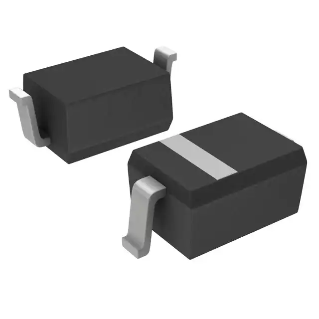
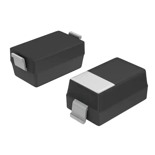
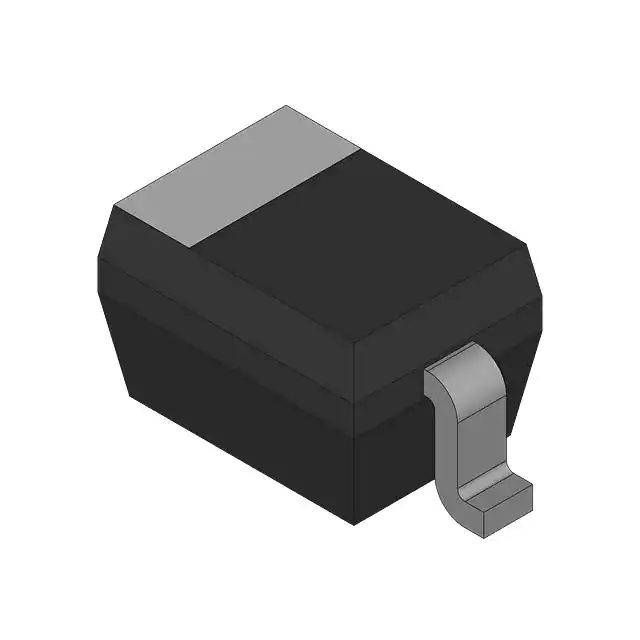
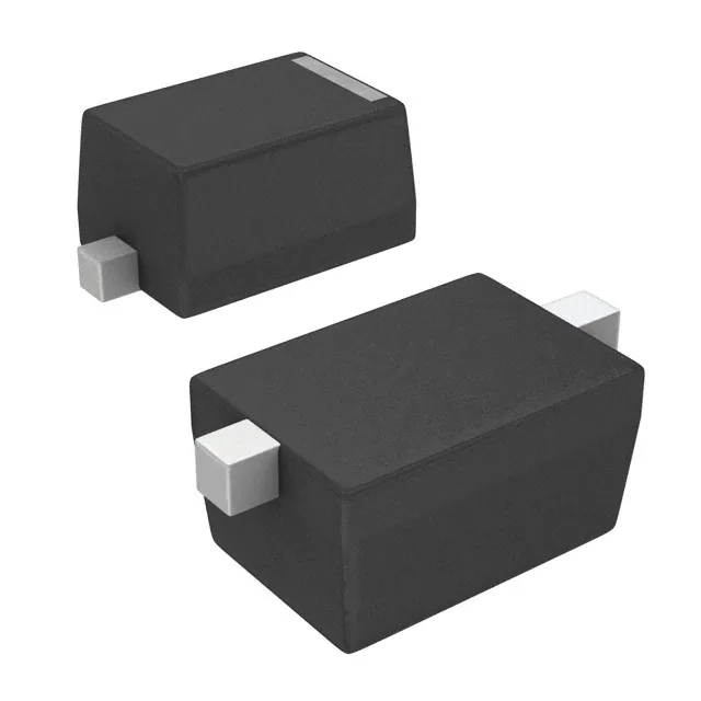
DO-213AC, MINI-MELF, SOD-80
Datasheet:
AetrixLL41-GS18.pdf
Description:
DIODE SCHOT 100V 100MA SOD80
Quantity:
Payment:
Payment
Shipping:
Shipping

Inventory:9,875

Please send an inquiry. Send us your inquiry, and we will respond immediately.

Part Number
Quantity*
Price
Name*
Company
Email*
Comments

Product details

Overview

LL41-GS18 from Vishay Semiconductors is a single small-signal Schottky diode in MiniMELF (SOD-80) package, rated for 100 V repetitive peak reverse voltage, 100 mA forward continuous current, and 200 mW power dissipation at 65 °C ambient. It delivers low forward voltage (450 mV typ. at 1 mA) and ultra-low leakage (100 nA at 50 V, 25 °C), suited for high-efficiency signal demodulation and clamp protection in portable DC-DC converters.

For engineers reviewing the LL41-GS18 datasheet, LL41-GS18 pinout, LL41-GS18 application, or LL41-GS18 equivalent, key selection criteria include its 2 pF junction capacitance at 1 V, 300 K/W thermal resistance, black cathode band marking, MiniMELF mechanical compatibility, and tape-and-reel packaging (10 k per 13" reel).

Technical Context

This Schottky diode uses a metal–semiconductor junction to achieve fast switching (no minority carrier storage) and low forward conduction loss. Its guardring-protected PN junction enhances ESD robustness without compromising reverse recovery speed.

Designed for ambient operation from –65 °C to +125 °C, the LL41-GS18 maintains stable leakage performance up to 100 °C (20 μA at 50 V), with thermal derating governed by a fixed 300 K/W junction-to-ambient resistance and 125 °C maximum junction temperature.

Key Specifications

ParameterValue and Actual Design Meaning
VRRM100 V - supports input rectification in 48 V nominal systems with 2× safety margin
IF100 mA continuous - suitable for bias networks and low-current signal paths
VF @ 1 mA450 mV typical - enables low-loss detection/clamping in battery-powered sensors
IR @ 50 V, 25 °C100 nA - ensures minimal standby current in always-on monitoring circuits
CD @ 1 V, 1 MHz2 pF - preserves signal integrity in RF detector and high-frequency clamp applications
RthJA300 K/W - requires no heatsink for ≤100 mW dissipation in free-air PCB mounting
Tj max125 °C - allows operation in sealed industrial enclosures without active cooling

Pinout & Package

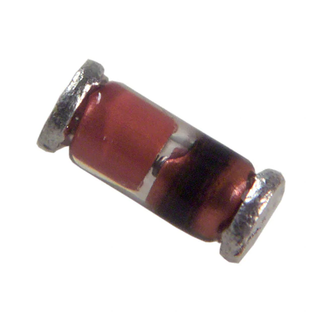
MiniMELF (SOD-80) cylindrical glass package, 3.3–3.7 mm length, 1.4–1.6 mm diameter, black cathode band marking. Weight ≈31 mg. No discrete pins; anode and cathode are axial terminals defined by band orientation.

Pin/TerminalCircuit RoleDesign Meaning
Anode (unbanded end)Forward current entry pointConnected to higher-potential node in clamping or rectifying configuration
Cathode (black band end)Forward current exit / reverse blocking terminalReference node for voltage reference, ESD protection return path, or logic-level sensing

Key Features

FeatureDesign Value
Low forward voltage450 mV typ. at 1 mA enables >95 % efficiency in low-voltage signal detection
Guardring-protected junctionEnhances ESD immunity without adding series resistance or slowing response
Ultra-low leakage100 nA at 50 V/25 °C minimizes error in precision sample-and-hold or high-Z sensor interfaces
MiniMELF ruggednessGlass-body construction withstands mechanical stress in vibration-prone automotive modules
High VRRM/IF ratio100 V / 100 mA supports wide-input-range power management in space-constrained designs

Applications

RF Signal DetectorLow-Power Voltage Clamp

Use Scenario: Demodulating AM signals in sub-GHz ISM-band receivers with <100 μA quiescent current budget.

IC Role / Device Role / Timing Role: Schottky detector diode converting RF envelope to baseband DC voltage.

Use Value: 2 pF capacitance and 450 mV VF preserve sensitivity and linearity below –20 dBm input.

Use Scenario: Protecting ADC inputs in battery-operated environmental sensors against ±15 V transients.

IC Role / Device Role / Timing Role: Fast clamping diode shunting overvoltage to rail before damage occurs.

Use Value: 350 mA IFRM and guardring structure sustain repeated ESD events without parameter shift.

DC-DC Feedback SnubberHigh-Speed Logic-Level Translator

Use Scenario: Damping switching-node ringing in 1 MHz synchronous buck converters powering FPGA core rails.

IC Role / Device Role / Timing Role: Passive snubber diode absorbing high-frequency energy during MOSFET turn-off.

Use Value: Low CD avoids resonance with layout inductance; 100 V rating covers worst-case overshoot.

Use Scenario: Level-shifting 1.8 V GPIO to 3.3 V I²C bus while maintaining <10 ns propagation delay.

IC Role / Device Role / Timing Role: Bidirectional passive translator using forward conduction and reverse isolation.

Use Value: Sub-500 mV VF ensures valid logic-high threshold; 100 nA IR prevents pull-up current loss.

Equivalent & Alternatives

The following parts are listed as comparable options for similar small-signal Schottky diode applications.

Alternative PartTechnical DifferenceApplication DifferenceSelection Advice
BAT41-TRDO-35 (DO-204AH) package; 100 V VRRM, 150 mA IF, 500 mV VF @ 1 mALarger footprint; higher thermal mass but lower current rating than LL41-GS18Choose BAT41-TR when board space permits larger axial leaded package and higher surge tolerance is needed
1N5711-TDO-35 package; 70 V VRRM, 150 mA IF, 430 mV VF @ 1 mA, 4 pF CDLower breakdown voltage limits use in >60 V systems; higher capacitance affects RF performanceSelect 1N5711-T only for cost-sensitive, non-RF, low-voltage (<50 V) clamp or detector roles

Compared with BAT41-TR and 1N5711-T, the LL41-GS18 offers superior RF suitability due to its 2 pF capacitance and MiniMELF high-frequency layout stability, while maintaining tighter VF consistency and smaller PCB area than DO-35 alternatives.

Availability

LL41-GS18 is available at Aetrix Electronics and suitable for portable medical monitors, automotive body control modules, and industrial IoT sensor nodes requiring stable component supply, long-lifecycle availability, and consistent MiniMELF form factor.

Supply support for LL41-GS18 includes scheduled delivery planning, volume procurement assistance, BOM continuity management, traceable sourcing, and lifecycle availability coordination for OEM customers, industrial embedded developers, connected-device designers, and electronics production programs.

Manufacturer

Vishay Semiconductors is a global leader in discrete semiconductors, specializing in high-reliability diodes, MOSFETs, and optoelectronics for industrial, automotive, and computing markets.

The LL41-GS18 belongs to Vishay's MiniMELF Schottky diode family, engineered for high-frequency signal integrity and low-power efficiency in space-constrained, thermally demanding applications.

FAQ

What is the cathode identification method for LL41-GS18?

The cathode of the LL41-GS18 is marked by a black band on the MiniMELF glass body. This band aligns with the cathode terminal, which must be connected to the lower-potential node in forward-biased operation. The anode is the opposite, unbanded end. This marking is standardized across all SOD-80 packaged variants of the LL41-GS18 and verified in Vishay document 85671 rev. 2.0.

Does LL41-GS18 have a specified reverse recovery time?

No, the LL41-GS18 does not specify reverse recovery time (trr) because it is a Schottky diode with majority-carrier conduction-no minority carrier storage exists. Its switching is inherently fast and limited only by junction capacitance (2 pF) and circuit inductance. This behavior is confirmed in the "Small Signal Schottky Diode" product classification and absence of trr in the Electrical Characteristics table of the LL41-GS18 datasheet.

Can LL41-GS18 replace BAT41 in existing designs?

The LL41-GS18 can functionally replace BAT41 in many applications due to identical VRRM (100 V) and similar VF, but it is not a drop-in replacement: BAT41 uses DO-35 packaging while LL41-GS18 uses MiniMELF (SOD-80), requiring footprint and reflow profile adjustments. Thermal resistance also differs (300 K/W vs. ~250 K/W for DO-35), so power derating must be revalidated for the LL41-GS18.

What is the maximum surge current rating for LL41-GS18?

The LL41-GS18 has a repetitive peak forward surge current (IFSM) rating of 750 mA at tp = 10 ms, as specified in the Absolute Maximum Ratings table. This value assumes single half-sine waveform conditions and applies only when junction temperature remains within 125 °C. It is validated per JEDEC test methods and documented in Vishay's LL41-GS18 datasheet revision 2.0.

Is LL41-GS18 compliant with RoHS and REACH?

Yes, the LL41-GS18 is RoHS-compliant and REACH-conformant, as confirmed by Vishay's material categorization statement in document 85671 and the "Material categorization" feature note. Compliance status is tracked under Vishay's standard product sustainability framework, and full declarations are available upon request through Aetrix Electronics' technical support team for the LL41-GS18.

LL41-GS18 Specifications

Product attributes
Attribute value
Manufacturer:
Vishay General Semiconductor - Diodes Division
Series:
-
Package/Case:
DO-213AC, MINI-MELF, SOD-80
Packaging:
Tape & Reel (TR)
Product Status:
Active
Technology:
Schottky
Voltage - DC Reverse (Vr) (Max):
100 V
Current - Average Rectified (Io):
100mA
Voltage - Forward (Vf) (Max) @ If:
1 V @ 200 mA
Speed:
Small Signal =< 200mA (Io), Any Speed
Reverse Recovery Time (trr):
-
Current - Reverse Leakage @ Vr:
100 nA @ 50 V
Capacitance @ Vr, F:
2pF @ 1V, 1MHz
Grade:
Automotive
Qualification:
AEC-Q101
Mounting Type:
Surface Mount
Supplier Device Package:
SOD-80 MiniMELF
Operating Temperature - Junction:
125°C (Max)

LL41-GS18 FAQ

1.How can I place an order for LL41-GS18 through Aetrix?

Please submit a Request for Quotation (RFQ) for LL41-GS18 on Aetrix. Our sales agent will provide a competitive quotation and guide you through the order confirmation once you accept the terms.

2.Are the price and stock information for LL41-GS18 reliable?

The price and inventory of LL41-GS18 are updated periodically and may fluctuate due to market conditions. Stock and pricing data are typically refreshed every 24 hours. Quotation validity for LL41-GS18 is usually 5 days.

3.What payment methods are accepted for LL41-GS18?

We accept Wire Transfer, PayPal, Credit Card, Western Union, MoneyGram, and Escrow for LL41-GS18 transactions.

Note: Certain payment methods may incur a processing fee.

4.How is shipping managed for LL41-GS18?

LL41-GS18 orders can be shipped via leading logistics carriers, including DHL, UPS, FedEx, TNT, or Registered Mail.

Once your LL41-GS18 order is processed, you will receive an email with the shipment details and tracking number.

Note: Tracking information may take up to 24 hours to appear. Express delivery typically takes 3–5 business days.

5.How can I obtain technical support or documentation for LL41-GS18?

For technical support, including LL41-GS18 datasheets, pinout diagrams, or application guidance, please contact our engineering support team. They can provide detailed documentation and assistance for your LL41-GS18 requirements.

6.How does Aetrix verify that LL41-GS18 is sourced from the original manufacturer or authorized distributors?

All LL41-GS18 products on Aetrix are procured from qualified distributors and authorized channels. Our dedicated quality assurance team conducts strict verification, including traceability checks and, if necessary, third-party testing. This ensures that LL41-GS18 meets industry standards.

7.What is the process for return or replacement of LL41-GS18?

All LL41-GS18 units undergo pre-shipment inspection (PSI). If there is an issue with LL41-GS18, returns or replacements are accepted under the following conditions:

1.Quantity discrepancies, incorrect items, or visible external defects (such as breakage or corrosion), acknowledged by Aetrix.

2.The issue is reported within 90 days of delivery.

3.The LL41-GS18 part is unused and in its original packaging.

Return procedure for LL41-GS18:

1.Submit a request within 90 days.

2.Obtain a Return Material Authorization (RMA) from Aetrix.

LL41-GS18 Tags
  • LL41-GS18
  • LL41-GS18 PDF
  • LL41-GS18 Datasheet
  • LL41-GS18 Specifications
  • LL41-GS18 Images
  • Vishay General Semiconductor - Diodes Division
  • Vishay General Semiconductor - Diodes Division LL41-GS18
  • Buy LL41-GS18
  • LL41-GS18 Price
  • LL41-GS18 Distributor
  • LL41-GS18 Supplier
  • LL41-GS18 Wholesale
Related Products
1N4448X-TP
1N4448X-TP

Micro Commercial Co

1N4148WX-TP
1N4148WX-TP

Micro Commercial Co

1N4148TR
1N4148TR

onsemi

MMSD4148T1G
MMSD4148T1G

onsemi

MMBD914LT3G
MMBD914LT3G

onsemi

BAS16HT1G
BAS16HT1G

onsemi

1N914BWT
1N914BWT

onsemi

BAS21LT1G
BAS21LT1G

onsemi

LL4148
LL4148

onsemi

BAS16LT1G
BAS16LT1G

onsemi

MMSD914T1G
MMSD914T1G

onsemi

BAV21W-7-F
BAV21W-7-F

Diodes Incorporated

Tech Hub

Search

Search

PRODUCT

PRODUCT

PHONE

PHONE

USER

USER