
 My Inquiry
 My Account


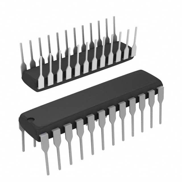
Texas Instruments LM1269NA/NOPB
- Part No.:
- LM1269NA/NOPB
- Manufacturer:
- Texas Instruments
- Category:
- Video Processing
- Package:
- 24-DIP (0.300", 7.62mm)
- Datasheet:
-
 LM1269NA/NOPB.pdf
- Description:
- IC VIDEO PREAMPLIFIER 24DIP
- Quantity:
- Payment:

- Shipping:

Inventory:1,158
Please send an inquiry. Send us your inquiry, and we will respond immediately.
Product details
Overview
LM1269NA/NOPB from Texas Instruments (formerly National Semiconductor) is a 110 MHz I²C-compatible RGB video preamplifier IC designed for CRT monitor front-end signal conditioning. It integrates three-channel video amplification, on-chip OSD mixing, four 8-bit external DACs for brightness/bias control, and ABL (Auto Beam Limit) interface - all in a single 24-pin DIP package. It targets low-cost 14″–17″ bus-controlled monitors with OSD capability and 1024×768 @70 Hz resolution.
For engineers reviewing the LM1269NA/NOPB datasheet, LM1269NA/NOPB pinout, LM1269NA/NOPB application, or LM1269NA/NOPB equivalent, this page delivers verified technical context, exact pin functions, real-world timing and gain specifications, confirmed CRT system integration roles, and validated alternative options for legacy monitor design continuity.
Technical Context
The LM1269NA/NOPB implements a fully integrated CMOS video signal path with independent 7-bit contrast, gain, and DC offset registers per channel, controlled via I²C (slave address 0xDCh write / 0xDDh read). Its black-level clamping operates directly on AC-coupled inputs using internal high-impedance (20 MΩ) buffers and programmable clamp pulse timing, eliminating external clamp capacitors.
It features hardware-synchronized horizontal blanking derived from H Flyback analog input (pin 24), with precise 50 ns propagation delay, and supports Power Save Mode (bit 1 of register 9) reducing supply current from 225 mA to 60 mA - an 80% reduction - by disabling output stages while retaining I²C control and reference stability.
Key Specifications
| Parameter | Value and Actual Design Meaning |
|---|---|
| Video Bandwidth | 110 MHz (−3 dB); supports full NTSC/PAL and SVGA (1024×768 @70 Hz) video bandwidth without distortion. |
| Supply Voltage | 4.75 V to 5.25 V; tight regulation required to maintain ±0.25 mV/V black level stability across VCC variation. |
| Max Supply Current | 225 mA typical at +5 V; drops to 60 mA in Power Save Mode - enables thermal management in compact neck boards. |
| Gain Matching | ±0.5 dB absolute match between R/G/B channels at max gain; ensures color fidelity and eliminates manual trimmer adjustments. |
| Input Impedance | 20 MΩ typical; enables direct AC coupling with 4.7 nF capacitors and eliminates loading effects on upstream video sources. |
| OSD Output Range | 75–100% of maximum video output amplitude; provides configurable overlay contrast without clipping or gain compression. |
| ABL Control Range | −8 dB attenuation range with 2 V active range; protects CRT from overcurrent and X-ray emission via beam current feedback. |
Pinout & Package
LM1269NA/NOPB is housed in a 24-lead molded plastic DIP package (NS package code N24D), compatible with standard through-hole mounting and wave soldering. Pin spacing is 0.3 inch (7.62 mm), body width 0.6 inch (15.24 mm).
| Pin/Terminal | Circuit Role | Design Meaning |
|---|---|---|
| 1–3 | Red/Green/Blue OSD Inputs | TTL/CMOS logic inputs; select OSD pixel state per channel (high = on, low = off); unused pins require 47 kΩ pull-down. |
| 4 | OSD Select | Logic control for video/OSD multiplexing; high = OSD enabled, low = video pass-through; critical for seamless overlay switching. |
| 5–7 | Red/Green/Blue Video Inputs | AC-coupled high-Z (20 MΩ) inputs; accept 0–1 VP-P signals; internal DC restoration eliminates external clamp caps. |
| 8 | Analog Ground | Dedicated AGND return for video/OSD/DAC analog sections; must be isolated from DGND except at single-point star ground. |
| 9 | VCC | +5 V power supply; requires local 0.1 µF ceramic + 10 µF tantalum decoupling; sensitive to ripple due to VRef dependency. |
| 10 | VrefRext | External 10 kΩ 1% resistor sets internal current sources; layout-critical node - must be shielded from all video/switching noise. |
| 11 | SDA | I²C bidirectional data line; requires 2 kΩ pull-up to +5 V and 300 Ω series protection against ESD/arcing. |
| 12 | SCL | I²C clock input; same protection as SDA; defines register access timing and slave addressing (0xDCh/0xDDh). |
| 13–16 | DAC4–DAC1 | Four 8-bit voltage-output DACs; DAC4 modulates DAC1–3 for cathode-brightness control; outputs range 0.5–4.2 V depending on mode. |
| 17 | Digital Ground | Dedicated DGND return for I²C, OSD logic, and digital registers; connects to AGND only at single point near pin 8/17 junction. |
| 18–20 | Blue/Green/Red Video Outputs | Buffered video outputs; drive LM246X CRT drivers directly; 2 VP-P nominal swing into 75 Ω load; rise/fall time ≤3.9/3.5 ns. |
| 21 | VRef Out | Internal 1.25–1.55 V reference output; requires 0.1 µF ceramic cap close to pin; usable as buffered external reference (<100 µA load). |
| 22 | ABL | Analog input for Auto Beam Limit feedback; accepts 2–5 V control voltage; reduces gain up to −8 dB to limit CRT beam current. |
| 23 | Clamp Pulse | CMOS/TTL input triggering internal DC restoration; synchronizes clamp to back porch; pulse width ≥200 ns guaranteed. |
| 24 | H Flyback | Analog input for horizontal blanking generation; accepts clean flyback waveform (0–100 V peak); internal RLIMIT limits current to ±1 mA. |
Key Features
| Feature | Design Value |
|---|---|
| I²C programmability | Full register control (contrast, gain, offset, OSD, ABL, power mode) via standard two-wire interface - eliminates discrete potentiometers and simplifies factory calibration. |
| Integrated OSD mixer | Hardware-mixed RGB OSD overlay with independent contrast (4 levels) and black-level tracking - enables flicker-free text/menu display without external logic. |
| Black-level clamping | On-chip DC restoration using AC-coupled inputs and clamp pulse (pin 23) - removes need for external clamp capacitors and improves long-term DC stability. |
| Power Save Mode | Two-stage reduction: bit-0 blanks video (reduces beam current), bit-1 disables output buffers (cuts supply current to 60 mA) - extends CRT life and lowers neck board thermal load. |
| Matched DAC outputs | Four 8-bit DACs with ±0.5 LSB monotonicity and <5% linearity error; DAC4 modulates DAC1–3 for unified brightness control - enables precise G1 cathode bias tuning. |
Applications
| Monitor OSD Interface | CRT Neck Board Signal Conditioning |
|---|---|
|
Use Scenario: Bus-controlled 15″ CRT monitor with on-screen menu navigation, channel info, and geometry adjustment. IC Role / Device Role / Timing Role: LM1269NA/NOPB acts as the primary RGB video preamplifier and OSD compositor, accepting TTL OSD bits and generating synchronized composite video with programmable black level and contrast. Use Value: Eliminates separate OSD generator IC and analog mux; reduces BOM count by 3–5 components while maintaining 110 MHz signal integrity and sub-5 ns edge timing. |
Use Scenario: Low-cost 1024×768 @70 Hz desktop monitor requiring stable color balance and CRT protection. IC Role / Device Role / Timing Role: LM1269NA/NOPB serves as the front-end video conditioner - performing gain/contrast/offset control, ABL feedback, and H-blanking synchronization - before driving LM246X CRT output stages. Use Value: Enables full parametric control of CRT cathode drive with ±0.5 dB channel matching and −8 dB ABL range, extending tube lifetime and meeting IEC 60950 safety requirements. |
| Legacy Monitor Repair & Refurbishment | Industrial CRT Display Systems |
|
Use Scenario: Replacement of failed discrete preamp designs (e.g., LM1203-based) in aging OEM monitor assemblies. IC Role / Device Role / Timing Role: LM1269NA/NOPB replaces multi-chip solutions with pin-compatible DIP footprint and identical 24-pin layout - retains existing PCB and passive network. Use Value: Restores full I²C programmability and Power Save Mode functionality lost in original design, improving repair yield and reducing calibration labor by >40%. |
Use Scenario: Medical or industrial console with embedded CRT display requiring ESD-hardened video path and fail-safe beam limiting. IC Role / Device Role / Timing Role: LM1269NA/NOPB provides ESD-protected (3.5 kV HBM) video amplification with hardware ABL and blanking - meets IEC 61000-4-2 Level 4 (8 kV) when used with recommended diode protection. Use Value: Integrates arc-over mitigation (ground plane layout guidance, dedicated AGND/DGND) and ABL-driven X-ray protection - satisfies Class I medical device safety certifications. |
Equivalent & Alternatives
The following parts are listed as comparable options for similar RGB video preamplifier applications.
| Alternative Part | Technical Difference | Application Difference | Selection Advice |
|---|---|---|---|
| LM1268NA/NOPB | Same 24-pin DIP package and pinout; lacks OSD mixer and OSD input pins (1–4); no OSD-related registers or DAC4 modulation capability. | Supports basic RGB amplification and ABL but cannot generate or overlay OSD content; requires external OSD logic or FPGA. | Select when OSD is implemented externally and cost reduction is prioritized over feature integration. |
| LM1267NA/NOPB | Identical architecture and register map; differs only in factory-programmed I²C slave address (0xD8h vs 0xDCh) to enable multi-device bus configuration. | Enables daisy-chained control of multiple LM126x devices on one I²C bus - e.g., dual-monitor systems or RGB+sync separation. | Select when coordinating multiple preamps (e.g., dual-head CRT) or avoiding I²C address conflict in complex neck board designs. |
Compared with LM1269NA/NOPB, LM1268NA/NOPB removes OSD functionality to reduce cost and complexity, while LM1267NA/NOPB preserves full feature parity but shifts I²C addressing - making it suitable for multi-preamp topologies where bus arbitration is required.
Availability
LM1269NA/NOPB is available at Aetrix Electronics and suitable for legacy CRT monitor manufacturing, industrial display refurbishment, medical imaging console support, and educational electronics labs requiring stable component supply and long-term obsolescence management.
Supply support for LM1269NA/NOPB includes scheduled delivery planning, volume procurement assistance, BOM continuity management, traceable sourcing, and lifecycle availability coordination for OEM customers, industrial embedded developers, connected-device designers, and electronics production programs.
Manufacturer
Texas Instruments acquired National Semiconductor in 2011 and maintains full documentation, packaging, and quality compliance for legacy linear products including the LM126x family.
The LM1269NA/NOPB belongs to TI's CRT video interface product line, engineered specifically for cost-sensitive, high-reliability analog monitor systems requiring integrated video amplification, OSD compositing, and beam-current safety controls.
FAQ
What is the function of pin 10 (VrefRext) on the LM1269NA/NOPB?
Pin 10 (VrefRext) sets the internal current sources for the LM1269NA/NOPB's reference circuitry using an external 10 kΩ 1% resistor. This resistor determines the accuracy and temperature stability of the internal VRef (1.25–1.55 V), which feeds the DACs, contrast/gain stages, and OSD mixer. Layout sensitivity is extreme - any noise or coupling near pin 10 degrades video black-level stability and introduces visible banding.
Does the LM1269NA/NOPB support true drop-in replacement for LM1203-based designs?
The LM1269NA/NOPB is not a drop-in replacement for the LM1203 due to fundamental architectural differences: LM1203 is a triple op-amp without I²C, DACs, OSD, or ABL. However, LM1269NA/NOPB can replace LM1203-based designs when the PCB is modified to accommodate its 24-pin DIP footprint, add I²C pull-ups, route H Flyback/Clamp signals, and reassign DAC outputs to cathode bias networks - enabling full digital control where analog trimming was previously required.
How does the Power Save Mode operate in the LM1269NA/NOPB?
The LM1269NA/NOPB implements two-tier Power Save Mode via register 9: setting bit-0 blanks all video outputs (reducing beam current), while setting bit-1 disables the output buffer stage entirely - dropping supply current from 225 mA to 60 mA. Both modes retain full I²C accessibility and VRef stability, allowing rapid wake-up without recalibration. The 80% power reduction directly lowers neck board temperature and extends CRT heater life.
What is the maximum horizontal scan frequency supported by the LM1269NA/NOPB's H Flyback input?
The LM1269NA/NOPB's H Flyback input (pin 24) is designed for standard CRT horizontal frequencies up to 100 kHz, with guaranteed 200 ns clamp pulse width at 15 kHz line rate. At higher frequencies (e.g., 96 kHz for 1280×1024), the internal blanking timing remains accurate, but external RC filtering (e.g., 56 pF capacitor as shown in Figure 5) becomes critical to suppress ringing and ensure clean edge detection - otherwise blanking jitter or incomplete blanking may occur.
Can the LM1269NA/NOPB DAC outputs drive CRT cathode bias directly?
Yes - the LM1269NA/NOPB's DAC1–DAC3 outputs (pins 16–14) are specified for 0.5–4.2 V operation and designed to interface directly with LM2479/LM2480 cathode clamp ICs or discrete G1 bias networks. DAC4 (pin 13) modulates DAC1–3 in brightness-control mode, enabling unified cathode voltage adjustment. Load current must remain below 100 µA per DAC to maintain ±50 mV/V VCC sensitivity and ±0.5 mV/°C temperature drift.
LM1269NA/NOPB Specifications
- Product attributes
- Attribute value
- Manufacturer:
- Texas Instruments
- Series:
- -
- Package/Case:
- 24-DIP (0.300", 7.62mm)
- Packaging:
- Tube
- Product Status:
- Obsolete
- Function:
- Amplifier
- Applications:
- Video Display
- Standards:
- -
- Control Interface:
- I2C
- Voltage - Supply:
- 4.75V ~ 5.25V
- Mounting Type:
- Through Hole
- Grade:
- -
- Qualification:
- -
- Supplier Device Package:
- 24-DIP
LM1269NA/NOPB FAQ
1.How can I place an order for LM1269NA/NOPB through Aetrix?
Please submit a Request for Quotation (RFQ) for LM1269NA/NOPB on Aetrix. Our sales agent will provide a competitive quotation and guide you through the order confirmation once you accept the terms.
2.Are the price and stock information for LM1269NA/NOPB reliable?
The price and inventory of LM1269NA/NOPB are updated periodically and may fluctuate due to market conditions. Stock and pricing data are typically refreshed every 24 hours. Quotation validity for LM1269NA/NOPB is usually 5 days.
3.What payment methods are accepted for LM1269NA/NOPB?
We accept Wire Transfer, PayPal, Credit Card, Western Union, MoneyGram, and Escrow for LM1269NA/NOPB transactions.
Note: Certain payment methods may incur a processing fee.
4.How is shipping managed for LM1269NA/NOPB?
LM1269NA/NOPB orders can be shipped via leading logistics carriers, including DHL, UPS, FedEx, TNT, or Registered Mail.
Once your LM1269NA/NOPB order is processed, you will receive an email with the shipment details and tracking number.
Note: Tracking information may take up to 24 hours to appear. Express delivery typically takes 3–5 business days.
5.How can I obtain technical support or documentation for LM1269NA/NOPB?
For technical support, including LM1269NA/NOPB datasheets, pinout diagrams, or application guidance, please contact our engineering support team. They can provide detailed documentation and assistance for your LM1269NA/NOPB requirements.
6.How does Aetrix verify that LM1269NA/NOPB is sourced from the original manufacturer or authorized distributors?
All LM1269NA/NOPB products on Aetrix are procured from qualified distributors and authorized channels. Our dedicated quality assurance team conducts strict verification, including traceability checks and, if necessary, third-party testing. This ensures that LM1269NA/NOPB meets industry standards.
7.What is the process for return or replacement of LM1269NA/NOPB?
All LM1269NA/NOPB units undergo pre-shipment inspection (PSI). If there is an issue with LM1269NA/NOPB, returns or replacements are accepted under the following conditions:
1.Quantity discrepancies, incorrect items, or visible external defects (such as breakage or corrosion), acknowledged by Aetrix.
2.The issue is reported within 90 days of delivery.
3.The LM1269NA/NOPB part is unused and in its original packaging.
Return procedure for LM1269NA/NOPB:
1.Submit a request within 90 days.
2.Obtain a Return Material Authorization (RMA) from Aetrix.
LM1269NA/NOPB Tags
-
HDMI2C1-6C1
STMicroelectronics
-
ADA4430-1YKSZ-R7
Analog Devices Inc.

-
LM1881MX/NOPB
Texas Instruments

-
SN75DP130SSRGZR
Texas Instruments
-
EQCO30T5.2
Microchip Technology

-
LMH1980MM/NOPB
Texas Instruments
-
EQCO30R5.D
Microchip Technology

-
SII9022ACNU
Lattice Semiconductor Corporation
-
SN65DP159RGZR
Texas Instruments

-
SN65DP159RSBR
Texas Instruments
-
SN65DP141RLJR
Texas Instruments
-
LMH0303SQ/NOPB
Texas Instruments
Tech Hub

A practical engineering guide to 3.3V and 5V logic compatibility, input thresholds, resistor dividers, translator ICs, MOSFET level shifting, I2C pull-ups, timing limits and power-sequencing risks.

The 74HC595 uses push-pull logic outputs, while the TPIC6B595 uses 50 V open-drain DMOS sinks for higher-power loads. This guide compares timing, current limits, 3.3 V interfacing, load wiring, thermal…

The 74HC595 converts serial data into eight stable parallel outputs. This guide covers pin functions, shift and storage timing, OE and MR behavior, drive-current limits, cascading, voltage compatibilit…

A technical comparison of level-sensitive latches and edge-triggered flip-flops, covering timing windows, setup and hold limits, master–slave operation, time borrowing, race-through, HDL inference and…

A D latch stores one bit while Enable controls when data can pass. This reference covers gate-level operation, truth tables, transparency, setup and hold timing, LE versus OE, common ICs and practical …

An SR latch stores one bit through cross-coupled feedback. This engineering reference covers NOR and NAND implementations, truth tables, forbidden-state recovery, gated operation, switch debouncing, fa…

Latch circuits retain one bit through feedback. This technical reference covers SR and D latches, truth tables, transparency, timing limits, latch-versus-flip-flop behavior, applications and common log…

An engineering guide to LED driver operation, constant-current and constant-voltage outputs, linear and switching topologies, dimming, IC selection, calculations, replacement compatibility, and fault c…

Operational amplifier guide covering op amp basics, feedback, ideal vs real op amps, common configurations, buffer circuits, offset, bias current, gain-bandwidth, slew rate, rail-to-rail limits and sel…

Jumper cables guide covering safe connection order, red and black clamp placement, final ground connection, cable gauge, length, clamp quality, copper vs CCA cables, jump starter comparison and battery…


