
 My Inquiry
 My Account


Texas Instruments LM3915N-1
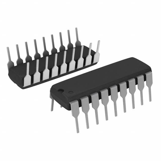
- Part No.:
- LM3915N-1
- Manufacturer:
- Texas Instruments
- Category:
- Display Drivers
- Package:
- 18-DIP (0.300", 7.62mm)
- Datasheet:
-
 LM3915N-1.pdf
- Description:
- IC DRVR DOT/BAR DISPLAY 18DIP
- Quantity:
- Payment:

- Shipping:

Inventory:1,485
Please send an inquiry. Send us your inquiry, and we will respond immediately.
Product details
Overview
LM3915N-1 from Texas Instruments is a monolithic logarithmic dot/bar display driver IC that senses analog input voltage and drives ten LEDs with 3 dB/step resolution across a 30 dB range. It operates from a single supply (3V to 25V), features an internal 1.25 V reference, programmable LED current (1–30 mA), and selectable bar or dot display mode via pin 9 - used in audio level meters, RF signal strength indicators, and vibration monitoring systems.
For engineers reviewing the LM3915N-1 datasheet, LM3915N-1 pinout, LM3915N-1 application, or LM3915N-1 equivalent, key selection considerations include its logarithmic 3 dB/step threshold accuracy (±1.5 dB max), ±35 V input tolerance without damage, open-collector NPN output structure, 18-pin PDIP package, and cascading capability for 60–90 dB extended-range displays.
Technical Context
The LM3915N-1 integrates a high-impedance input buffer, precision 10-step resistor ladder (16–36 kΩ total), and ten matched comparators referenced to the internal voltage divider. Its input accepts signals from ground to within 1.5 V of V+, and tolerates ±35 V overvoltage without false outputs or damage.
Display mode is controlled by pin 9: tied to V+ for bar mode (≤20 mV below V+), or open/floating for dot mode (>200 mV below V+). LED current is regulated at ~10× the reference load current drawn from pin 7, enabling brightness control independent of supply voltage and temperature.
Key Specifications
| Parameter | Value and Actual Design Meaning |
|---|---|
| Display Range | 30 dB logarithmic scale, 3 dB/step - enables precise visual representation of wide-dynamic-range signals like audio peaks or RF power. |
| Supply Voltage | 3 V to 25 V single supply - supports battery-powered portable meters and industrial 24 V systems without external regulators. |
| Input Overvoltage Tolerance | ±35 V on pin 5 - eliminates need for external clamping diodes in noisy or high-voltage sensing environments. |
| LED Current Range | 1 mA to 30 mA, programmable via reference load - allows direct drive of standard LEDs without series resistors while maintaining consistent brightness. |
| Reference Voltage | 1.25 V nominal (1.2–1.34 V) at pin 7–8 - sets full-scale range from 1.2 V to 12 V independent of supply, enabling flexible scaling for 0–10 V or -30 dBm to 0 dBm inputs. |
| Operating Temperature | 0°C to +70°C - rated for commercial and industrial ambient conditions; not specified for extended temperature grades. |
| Threshold Accuracy | ±0.5 dB to ±1.5 dB depending on step (e.g., ±0.5 dB at −3 dB, ±1.5 dB at −27 dB) - ensures reliable visual discrimination across full log scale. |
Pinout & Package
LM3915N-1 is housed in an 18-lead plastic dual in-line package (PDIP), designated N-18 by Texas Instruments. Thermal resistance is 55°C/W (junction-to-ambient), with maximum power dissipation of 1365 mW at 25°C ambient.
| Pin/Terminal | Circuit Role | Design Meaning |
|---|---|---|
| 1 | LED #10 Anode Driver Output | Open-collector NPN output; sinks current when active - drives LED cathode in common-anode configuration. |
| 2 | Ground (GND) | Signal and power return reference - must be star-connected near pin 2 to minimize noise-induced errors in bar mode. |
| 3 | Positive Supply (V+) | Single supply input (3–25 V); powers internal circuitry and supplies current to LED anodes via external VLED rail. |
| 4 | Low Reference (VRLO) | Bottom of internal 10-step divider - typically connected to GND or negative reference to set lower display bound. |
| 5 | Analog Input (SIG IN) | High-impedance buffer input (25–100 nA bias); accepts signals from GND to V+−1.5 V - directly interfaces with transducers or op-amp outputs. |
| 6 | High Reference (VRHI) | Top of internal divider - sets upper display bound; referenced to VRLO to define full-scale voltage range. |
| 7 | Reference Output (REF OUT) | 1.25 V source - develops fixed voltage across R1 to program LED current and full-scale range. |
| 8 | Reference Adjust (REF ADJ) | Current-sink node (75–120 μA) - adjusts reference voltage and sets LED drive current via external resistor network. |
| 9 | Mode Select (MODE) | Digital control input - high (≥V+−20 mV) selects bar graph; floating or low (≥200 mV below V+) selects moving-dot mode. |
| 10–18 | LED #1 to #9 Drivers | Open-collector NPN outputs - sink current for LEDs 1–9; pin 10 is LED #10, pins 11–18 correspond to LEDs 2–10 respectively per TI pin mapping. |
Key Features
| Feature | Design Value |
|---|---|
| Logarithmic 3 dB/step response | Enables accurate visual interpretation of exponentially varying signals (e.g., audio SPL, RF power) without digital computation. |
| Bar/dot mode selectability | Single-pin (pin 9) hardware configuration - simplifies design changes between steady-state level indication (bar) and transient tracking (dot). |
| Expandable 60–90 dB range | Multiple LM3915N-1 units cascade via pin 1 and pin 9 - supports wide-dynamic-range applications like broadcast VU meters or spectrum analyzers. |
| Input protection without external components | Withstands ±35 V on pin 5 indefinitely - reduces BOM count and PCB area in field-deployed instrumentation. |
| Regulated open-collector outputs | Delivers stable LED current (1–30 mA) across VLED = 2–17 V - eliminates need for per-LED current-limiting resistors and improves uniformity. |
Applications
| Audio Level Metering | RF Signal Strength Indication |
|---|---|
|
Use Scenario: Real-time visualization of line-level or microphone audio signals in studio mixers, portable recorders, or live sound consoles. IC Role / Device Role / Timing Role: Logarithmic analog-to-visual converter - converts instantaneous or rectified AC voltage into 10-step LED intensity proportional to dB level. Use Value: Provides faster response and higher visibility than analog meters while retaining intuitive logarithmic scaling familiar to audio engineers. |
Use Scenario: Front-panel signal strength display in UHF/VHF receivers, spectrum analyzers, or wireless test equipment. IC Role / Device Role / Timing Role: RF envelope detector interface - drives LEDs based on demodulated or detected RF amplitude after precision rectification. Use Value: Enables rapid identification of weak/strong channels without oscilloscope; ±35 V tolerance accommodates antenna-coupled inputs. |
| Vibration Monitoring System | Power Supply Fault Detection |
|
Use Scenario: Industrial machine health dashboard showing RMS or peak vibration amplitude from piezoelectric sensors. IC Role / Device Role / Timing Role: Analog threshold comparator array - maps sensor output voltage (e.g., 0–1 V = 0–100 mm/s) to discrete LED steps. Use Value: Delivers immediate visual alert at preset severity thresholds (e.g., LED #7 = warning, LED #10 = shutdown) without microcontroller overhead. |
Use Scenario: Overvoltage/undervoltage warning on DC power rails in telecom or server PSUs. IC Role / Device Role / Timing Role: Precision voltage monitor - compares rail voltage against internal divider to light LEDs at defined fault margins (e.g., ±5%, ±10%). Use Value: Achieves <1% full-scale error using internal reference and resistor ladder - eliminates calibration drift seen in comparator-based discrete solutions. |
Equivalent & Alternatives
The following parts are listed as comparable options for similar logarithmic display driver applications.
| Alternative Part | Technical Difference | Application Difference | Selection Advice |
|---|---|---|---|
| LM3914N-1 | Linear 1 V/step response instead of logarithmic 3 dB/step; identical pinout, supply range, and LED drive architecture. | Better suited for linear measurements (e.g., battery voltage, temperature) where equal voltage increments matter more than perceptual loudness or signal power. | Select LM3914N-1 only when display must reflect absolute voltage change rather than relative dB change - not interchangeable without recalibrating thresholds. |
| LM3916N-1 | Optimized VU meter response curve (quasi-log, −20 dB to +3 dB); includes built-in averaging and peak-hold timing; same 18-pin PDIP package. | Designed specifically for audio VU standards (IEC 60268); provides slower attack/release to match human perception of loudness, unlike LM3915N-1's instantaneous response. | Choose LM3916N-1 for broadcast or professional audio compliance; LM3915N-1 remains preferred for general-purpose log scaling and wider dynamic range flexibility. |
Compared with LM3914N-1 and LM3916N-1, the LM3915N-1 uniquely delivers true 3 dB/step logarithmic resolution across 30 dB, making it optimal for RF, acoustic, and vibration applications requiring perceptually uniform step spacing - whereas LM3914N-1 serves linear domains and LM3916N-1 targets standardized audio metering.
Availability
LM3915N-1 is available at Aetrix Electronics and suitable for audio level meters, RF signal strength indicators, and industrial vibration monitors requiring stable component supply and long-term production continuity.
Supply support for LM3915N-1 includes scheduled delivery planning, volume procurement assistance, BOM continuity management, traceable sourcing, and lifecycle availability coordination for OEM customers, industrial embedded developers, connected-device designers, and electronics production programs.
Manufacturer
Texas Instruments is a global semiconductor leader headquartered in Dallas, Texas, delivering analog, embedded processing, and logic solutions for industrial, automotive, and communications markets since 1930.
The LM3915N-1 belongs to TI's legacy analog display driver product line, designed specifically for high-visibility, low-complexity logarithmic LED indication in instrumentation and audio equipment - emphasizing ease of use, robust input protection, and cascading scalability.
FAQ
What is the operating temperature range for the LM3915N-1?
The LM3915N-1 is rated for operation from 0°C to +70°C. This commercial-grade specification aligns with its intended use in audio equipment, test instruments, and industrial panels where ambient temperatures remain within this band. It does not support extended industrial (−40°C to +85°C) or automotive temperature ranges, and derating is required above 70°C per its 55°C/W thermal resistance.
How does the LM3915N-1 achieve logarithmic 3 dB/step behavior?
The LM3915N-1 achieves logarithmic response through a precision 10-step internal resistor ladder (16–36 kΩ total) that divides the voltage between VRHI (pin 6) and VRLO (pin 4). Each comparator references one tap, producing thresholds spaced at exact 3 dB intervals (e.g., −3 dB, −6 dB… −27 dB) relative to full scale. This ladder is floating and can be biased to any two voltages ≥1.5 V below V+, preserving log spacing regardless of reference point.
Can the LM3915N-1 drive LCDs or vacuum fluorescent displays?
Yes, the LM3915N-1 datasheet explicitly states it can drive LCDs and vacuum fluorescent displays in addition to LEDs. Its open-collector NPN outputs (pins 1 and 10–18) sink current up to 30 mA and tolerate up to 25 V collector-emitter voltage, enabling direct interface with segment drivers or grid electrodes - provided external biasing and timing meet the display's AC drive requirements.
What is the purpose of pin 9 on the LM3915N-1?
Pin 9 is the Mode Select input that determines display behavior: when tied to V+ (pin 3), it configures the LM3915N-1 for bar graph mode where all LEDs up to the active threshold illuminate; when left open or pulled >200 mV below V+, it enables dot mode where only one LED lights at a time. This pin also enables cascading - in multi-device dot-mode chains, pin 9 of a lower-range device connects to pin 1 of the next higher-range device to coordinate carry logic.
Does the LM3915N-1 require external current-limiting resistors for LEDs?
No, the LM3915N-1 does not require external current-limiting resistors for LEDs because its outputs feature integrated current regulation. LED current is set by the load current drawn from the REF OUT (pin 7) and REF ADJ (pin 8) terminals - approximately 10× that reference current flows through each active LED. This eliminates part count, improves brightness uniformity, and maintains regulation across supply voltage and temperature variations.
LM3915N-1 Specifications
- Product attributes
- Attribute value
- Manufacturer:
- Texas Instruments
- Series:
- -
- Package/Case:
- 18-DIP (0.300", 7.62mm)
- Packaging:
- Tube
- Product Status:
- Obsolete
- Display Type:
- LED, LCD, Vacuum Fluorescent (VF)
- Configuration:
- Dot/Bar Display
- Interface:
- -
- Digits or Characters:
- 10 Steps
- Current - Supply:
- 6.1 mA
- Voltage - Supply:
- 3V ~ 25V
- Operating Temperature:
- 0°C ~ 70°C
- Grade:
- -
- Qualification:
- -
- Mounting Type:
- Through Hole
- Supplier Device Package:
- 18-DIP
LM3915N-1 FAQ
1.How can I place an order for LM3915N-1 through Aetrix?
Please submit a Request for Quotation (RFQ) for LM3915N-1 on Aetrix. Our sales agent will provide a competitive quotation and guide you through the order confirmation once you accept the terms.
2.Are the price and stock information for LM3915N-1 reliable?
The price and inventory of LM3915N-1 are updated periodically and may fluctuate due to market conditions. Stock and pricing data are typically refreshed every 24 hours. Quotation validity for LM3915N-1 is usually 5 days.
3.What payment methods are accepted for LM3915N-1?
We accept Wire Transfer, PayPal, Credit Card, Western Union, MoneyGram, and Escrow for LM3915N-1 transactions.
Note: Certain payment methods may incur a processing fee.
4.How is shipping managed for LM3915N-1?
LM3915N-1 orders can be shipped via leading logistics carriers, including DHL, UPS, FedEx, TNT, or Registered Mail.
Once your LM3915N-1 order is processed, you will receive an email with the shipment details and tracking number.
Note: Tracking information may take up to 24 hours to appear. Express delivery typically takes 3–5 business days.
5.How can I obtain technical support or documentation for LM3915N-1?
For technical support, including LM3915N-1 datasheets, pinout diagrams, or application guidance, please contact our engineering support team. They can provide detailed documentation and assistance for your LM3915N-1 requirements.
6.How does Aetrix verify that LM3915N-1 is sourced from the original manufacturer or authorized distributors?
All LM3915N-1 products on Aetrix are procured from qualified distributors and authorized channels. Our dedicated quality assurance team conducts strict verification, including traceability checks and, if necessary, third-party testing. This ensures that LM3915N-1 meets industry standards.
7.What is the process for return or replacement of LM3915N-1?
All LM3915N-1 units undergo pre-shipment inspection (PSI). If there is an issue with LM3915N-1, returns or replacements are accepted under the following conditions:
1.Quantity discrepancies, incorrect items, or visible external defects (such as breakage or corrosion), acknowledged by Aetrix.
2.The issue is reported within 90 days of delivery.
3.The LM3915N-1 part is unused and in its original packaging.
Return procedure for LM3915N-1:
1.Submit a request within 90 days.
2.Obtain a Return Material Authorization (RMA) from Aetrix.
LM3915N-1 Tags

-
PCA8561AHN/AY
NXP Semiconductors

-
SN74LS47N
Texas Instruments

-
PCF85176T/1Y
NXP Semiconductors
-
PCF85176H/1,518
NXP Semiconductors

-
BU9796AMUV-E2
Rohm Semiconductor
-
PCA85176H/Q900/1,5
NXP Semiconductors
-
PCF8537AH/1,518
NXP Semiconductors

-
LM3914VX/NOPB
Texas Instruments

-
PCF85134HL/1,118
NXP Semiconductors

-
AS1115-BSST
ams-OSRAM USA INC.
-
PCA8534AH/Q900/1,5
NXP Semiconductors
-
LM3914V/NOPB
Texas Instruments
Tech Hub

A practical engineering guide to 3.3V and 5V logic compatibility, input thresholds, resistor dividers, translator ICs, MOSFET level shifting, I2C pull-ups, timing limits and power-sequencing risks.

The 74HC595 uses push-pull logic outputs, while the TPIC6B595 uses 50 V open-drain DMOS sinks for higher-power loads. This guide compares timing, current limits, 3.3 V interfacing, load wiring, thermal…

The 74HC595 converts serial data into eight stable parallel outputs. This guide covers pin functions, shift and storage timing, OE and MR behavior, drive-current limits, cascading, voltage compatibilit…

A technical comparison of level-sensitive latches and edge-triggered flip-flops, covering timing windows, setup and hold limits, master–slave operation, time borrowing, race-through, HDL inference and…

A D latch stores one bit while Enable controls when data can pass. This reference covers gate-level operation, truth tables, transparency, setup and hold timing, LE versus OE, common ICs and practical …

An SR latch stores one bit through cross-coupled feedback. This engineering reference covers NOR and NAND implementations, truth tables, forbidden-state recovery, gated operation, switch debouncing, fa…

Latch circuits retain one bit through feedback. This technical reference covers SR and D latches, truth tables, transparency, timing limits, latch-versus-flip-flop behavior, applications and common log…

An engineering guide to LED driver operation, constant-current and constant-voltage outputs, linear and switching topologies, dimming, IC selection, calculations, replacement compatibility, and fault c…

Operational amplifier guide covering op amp basics, feedback, ideal vs real op amps, common configurations, buffer circuits, offset, bias current, gain-bandwidth, slew rate, rail-to-rail limits and sel…

Jumper cables guide covering safe connection order, red and black clamp placement, final ground connection, cable gauge, length, clamp quality, copper vs CCA cables, jump starter comparison and battery…


