
 My Inquiry
 My Account


Texas Instruments LM3S6100-IQC25-A2
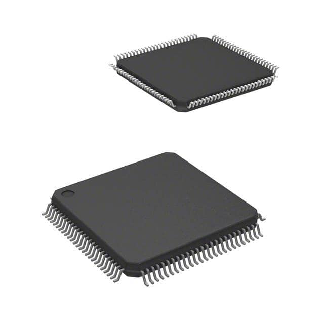
- Part No.:
- LM3S6100-IQC25-A2
- Manufacturer:
- Texas Instruments
- Category:
- Microcontrollers
- Package:
- 100-LQFP
- Datasheet:
-
 LM3S6100-IQC25-A2.pdf
- Description:
- IC MCU 32BIT 64KB FLASH 100LQFP
- Quantity:
- Payment:

- Shipping:

Inventory:1,042
Please send an inquiry. Send us your inquiry, and we will respond immediately.
Product details
Overview
LM3S6100-IQC25-A2 from Texas Instruments is a 32-bit ARM Cortex-M3 microcontroller with 256 KB flash, 64 KB SRAM, integrated Ethernet MAC, dual UARTs, SSI, GPIO, timers, and analog comparator. It operates at up to 50 MHz and supports industrial temperature range (–40°C to +85°C) in a 100-pin LQFP package. It serves as a system-on-chip controller for embedded networked devices requiring real-time control and wired connectivity.
For engineers reviewing the LM3S6100-IQC25-A2 datasheet, LM3S6100-IQC25-A2 pinout, LM3S6100-IQC25-A2 application, or LM3S6100-IQC25-A2 equivalent, key selection criteria include Ethernet MAC integration, 50 MHz Cortex-M3 performance, 100-pin LQFP footprint, industrial temperature rating, and absence of external PHY requirement.
Technical Context
The LM3S6100-IQC25-A2 implements the ARMv7-M architecture with NVIC, SysTick, MPU, and Thumb-2 instruction set. It integrates a full Ethernet MAC (MII interface only, no PHY), two UARTs supporting IrDA/SIR, one SSI port, eight 16/32-bit GPTMs, and a single analog comparator with internal reference.
It lacks USB, CAN, or ADC peripherals - distinguishing it from higher-tier Stellaris variants. Clocking is managed via an on-chip PLL with support for external crystal (1–25 MHz) or internal oscillator, and power management includes Sleep, Deep-Sleep, and Hibernate modes with wake-on-GPIO/UART/SSI.
Key Specifications
| Parameter | Value and Actual Design Meaning |
|---|---|
| CPU Core | ARM Cortex-M3, 32-bit RISC, up to 50 MHz - enables deterministic real-time execution with hardware divide and single-cycle multiply. |
| Flash Memory | 256 KB on-chip flash - sufficient for standalone firmware with Ethernet stack, TCP/IP, and application logic without external memory. |
| SRAM | 64 KB on-chip SRAM - supports Ethernet frame buffering, protocol stacks, and real-time data processing. |
| Ethernet Interface | MII-only MAC (no PHY) - requires external PHY IC (e.g., DP83848) and discrete magnetics; not plug-and-play Ethernet. |
| Operating Temperature | –40°C to +85°C - qualified for industrial environments including factory automation and remote monitoring nodes. |
| Package | 100-pin LQFP (14 × 14 mm, 0.5 mm pitch) - compatible with standard surface-mount assembly and debug via JTAG/SWD. |
| Peripherals | 2× UART, 1× SSI, 8× GPTM, 1× Analog Comparator, GPIO (up to 80 pins) - supports motor control I/O, serial sensor interfacing, and watchdog supervision. |
Pinout & Package
Package: 100-pin LQFP (Pb-free, RoHS-compliant), body size 14 mm × 14 mm, 0.5 mm lead pitch, exposed thermal pad (not electrically connected).
| Pin/Terminal | Circuit Role | Design Meaning |
|---|---|---|
| VDD, VDDA, VDDC | Power supply inputs | VDD (digital core), VDDA (analog), VDDC (clock system) - require separate 3.3 V filtering; VDDA must be clean for comparator reference stability. |
| GND | Ground reference | Multiple dedicated GND pins - mandatory star grounding near VDD pins to minimize noise coupling into analog and clock domains. |
| PD0–PD7, PE0–PE5, PF0–PF4, PG0–PG7, PH0–PH7, PK0–PK7 | GPIO banks | 80 total GPIOs with alternate functions - each bank supports digital input/output, interrupt, and peripheral mapping (e.g., UART0 on PA0/PA1). |
| RMII_TXD0, RMII_TXD1, RMII_TXEN, RMII_RXD0, RMII_RXD1, RMII_CRS_DV, RMII_REF_CLK | Ethernet MII signals | Dedicated 7-pin MII subset - connects directly to external PHY; no internal PHY or transformer integration. |
| U0RX, U0TX, U1RX, U1TX | UART I/O | Two independent full-duplex UART channels - support RS-232/RS-485 level-shifting and IrDA modulation via external circuitry. |
| SSI0CLK, SSI0FSS, SSI0RX, SSI0TX | Synchronous Serial Interface | Four-wire SPI-compatible interface - drives sensors, EEPROMs, or DACs with programmable bit rate and frame format. |
| XTAL, XTAL32K | Clock inputs | Primary 1–25 MHz crystal input and optional 32.768 kHz RTC crystal - enables precise timekeeping and low-power wake-up capability. |
Key Features
| Feature | Design Value |
|---|---|
| Integrated Ethernet MAC | Reduces BOM count by eliminating need for external MAC IC; requires external PHY but simplifies protocol stack integration in bare-metal or FreeRTOS environments. |
| ARM Cortex-M3 Core | Delivers 1.25 DMIPS/MHz performance with nested vectored interrupts - ensures low-latency response to Ethernet packet arrivals and timer events. |
| On-chip Flash & SRAM | 256 KB flash + 64 KB SRAM eliminates external memory interface - reduces PCB layer count and EMI risk in compact industrial designs. |
| Industrial Temperature Range | Rated for –40°C to +85°C operation - validated across thermal cycling and voltage extremes, suitable for uncontrolled cabinet or outdoor enclosure deployment. |
| Dual UART with IrDA Support | Enables local diagnostics over IR and remote configuration via RS-232/485 - avoids dedicated debug ports and simplifies field service access. |
Applications
| Industrial Ethernet Node | Remote Sensor Gateway |
|---|---|
Use Scenario: Standalone PLC I/O module communicating over Modbus TCP in factory floor networks. IC Role / Device Role / Timing Role: Primary system controller executing real-time I/O scanning, TCP/IP stack, and Modbus protocol parsing. Use Value: Integrated Ethernet MAC eliminates external MAC+PHY complexity while 50 MHz Cortex-M3 ensures sub-10 ms cycle times for 100-node networks. | Use Scenario: Battery-powered environmental sensor aggregator transmitting data via Ethernet to cloud gateway. IC Role / Device Role / Timing Role: Central coordinator managing sensor polling, data formatting, and Ethernet frame transmission. Use Value: Low-power sleep modes (Hibernate with RTC wake) extend battery life; dual UARTs enable simultaneous sensor command and debug logging. |
| Networked Motor Controller | Building Automation Panel |
Use Scenario: AC induction motor drive with speed feedback, fault monitoring, and EtherNet/IP interface. IC Role / Device Role / Timing Role: Real-time motion controller handling PWM generation, encoder capture, and network command interpretation. Use Value: Eight general-purpose timers support simultaneous PWM, quadrature decoding, and watchdog supervision - all synchronized to Ethernet packet timing. | Use Scenario: HVAC control panel integrating temperature, humidity, and damper actuator control with BACnet/IP support. IC Role / Device Role / Timing Role: Application processor running BACnet stack, UI logic, and peripheral drivers. Use Value: 64 KB SRAM accommodates BACnet object tables and concurrent Ethernet/UART traffic; analog comparator monitors supply rail integrity. |
Equivalent & Alternatives
The following parts are listed as comparable options for similar microcontroller applications.
| Alternative Part | Technical Difference | Application Difference | Selection Advice |
|---|---|---|---|
| LM3S6965-IQC50-A2 | Higher clock (50 MHz vs. 25 MHz base), 256 KB flash, 64 KB SRAM, adds USB OTG and CAN - same 100-pin LQFP package. | Supports USB device/host and CAN bus - required for automotive diagnostics or PC-connected firmware updates. | Select when USB or CAN is mandatory; LM3S6100-IQC25-A2 remains optimal for Ethernet-only, cost-sensitive industrial nodes. |
| TM4C123GH6PM | Newer ARM Cortex-M4F core (80 MHz), FPU, 256 KB flash, 32 KB SRAM, integrated PHY option, enhanced peripherals - 64-pin LQFP. | Smaller footprint, floating-point math acceleration, and optional PHY reduce component count - but requires PCB redesign and software migration. | Choose for new designs needing higher performance or FPU; LM3S6100-IQC25-A2 suits legacy Stellaris codebases and fixed-footprint upgrades. |
Compared with LM3S6100-IQC25-A2, LM3S6965-IQC50-A2 adds USB/CAN at identical pinout, while TM4C123GH6PM offers M4F performance and PHY integration in smaller package - both require firmware adaptation, making LM3S6100-IQC25-A2 ideal for stable, Ethernet-centric industrial deployments.
Availability
LM3S6100-IQC25-A2 is available at Aetrix Electronics and suitable for industrial Ethernet nodes, remote sensor gateways, networked motor controllers, and building automation panels requiring stable component supply and long-term manufacturability.
Supply support for LM3S6100-IQC25-A2 includes scheduled delivery planning, volume procurement assistance, BOM continuity management, traceable sourcing, and lifecycle availability coordination for OEM customers, industrial embedded developers, connected-device designers, and electronics production programs.
Manufacturer
Texas Instruments is a global semiconductor company headquartered in Dallas, Texas, delivering analog, embedded processing, and wireless technologies since 1930.
The Stellaris LM3S family was designed specifically for cost-sensitive, real-time embedded applications requiring Ethernet connectivity and deterministic control - targeting industrial automation, building systems, and networked instrumentation.
FAQ
Does LM3S6100-IQC25-A2 include an integrated Ethernet PHY?
No, LM3S6100-IQC25-A2 contains only an Ethernet MAC with MII interface. An external PHY IC (e.g., TI DP83848) and Ethernet magnetics are required for physical-layer connectivity. This separation allows design flexibility in PHY selection and signal integrity optimization.
What is the maximum operating frequency of LM3S6100-IQC25-A2?
The LM3S6100-IQC25-A2 operates at up to 50 MHz using its on-chip PLL. The "25" in the part number refers to the ambient temperature grade (–40°C to +85°C), not clock speed. Its Cortex-M3 core delivers consistent 50 MHz performance under industrial thermal conditions.
Which development tools support LM3S6100-IQC25-A2 firmware development?
LM3S6100-IQC25-A2 is supported by TI's Code Composer Studio v5–6, Keil MDK-ARM v4–5, and IAR Embedded Workbench for ARM. StellarisWare Peripheral Driver Library and LM3S6100-specific startup files are included in TI's official SDK releases through 2014.
Is LM3S6100-IQC25-A2 pin-compatible with other Stellaris LM3S devices?
LM3S6100-IQC25-A2 uses a 100-pin LQFP package shared with LM3S6965-IQC50-A2 and LM3S8962-IQC50-A2, enabling mechanical compatibility. However, peripheral pin mappings differ - for example, Ethernet MII signals occupy different pins across variants - so PCB layout is not interchangeable.
Does LM3S6100-IQC25-A2 support USB or CAN interfaces?
No, LM3S6100-IQC25-A2 does not include USB or CAN controllers. It provides Ethernet MAC, dual UARTs, SSI, timers, GPIO, and analog comparator only. For USB or CAN, consider LM3S6965-IQC50-A2 or newer TM4C series devices.
LM3S6100-IQC25-A2 Specifications
- Product attributes
- Attribute value
- Manufacturer:
- Texas Instruments
- Package/Case:
- 100-LQFP
- Series:
- Stellaris® ARM® Cortex®-M3S 6000
- Packaging:
- Tray
- Product Status:
- Active
- Programmable:
- Verified
- Core Processor:
- ARM® Cortex®-M3
- Core Size:
- 32-Bit Single-Core
- Speed:
- 25MHz
- Connectivity:
- Ethernet, IrDA, Microwire, SPI, SSI, UART/USART
- Peripherals:
- Brown-out Detect/Reset, POR, PWM, WDT
- Number of I/O:
- 30
- Program Memory Size:
- 64KB (64K x 8)
- Program Memory Type:
- FLASH
- EEPROM Size:
- -
- RAM Size:
- 16K x 8
- Voltage - Supply (Vcc/Vdd):
- 2.25V ~ 2.75V
- Data Converters:
- -
- Oscillator Type:
- Internal
- Operating Temperature:
- -40°C ~ 85°C (TA)
- Grade:
- -
- Qualification:
- -
- Mounting Type:
- Surface Mount
- Supplier Device Package:
LM3S6100-IQC25-A2 FAQ
1.How can I place an order for LM3S6100-IQC25-A2 through Aetrix?
Please submit a Request for Quotation (RFQ) for LM3S6100-IQC25-A2 on Aetrix. Our sales agent will provide a competitive quotation and guide you through the order confirmation once you accept the terms.
2.Are the price and stock information for LM3S6100-IQC25-A2 reliable?
The price and inventory of LM3S6100-IQC25-A2 are updated periodically and may fluctuate due to market conditions. Stock and pricing data are typically refreshed every 24 hours. Quotation validity for LM3S6100-IQC25-A2 is usually 5 days.
3.What payment methods are accepted for LM3S6100-IQC25-A2?
We accept Wire Transfer, PayPal, Credit Card, Western Union, MoneyGram, and Escrow for LM3S6100-IQC25-A2 transactions.
Note: Certain payment methods may incur a processing fee.
4.How is shipping managed for LM3S6100-IQC25-A2?
LM3S6100-IQC25-A2 orders can be shipped via leading logistics carriers, including DHL, UPS, FedEx, TNT, or Registered Mail.
Once your LM3S6100-IQC25-A2 order is processed, you will receive an email with the shipment details and tracking number.
Note: Tracking information may take up to 24 hours to appear. Express delivery typically takes 3–5 business days.
5.How can I obtain technical support or documentation for LM3S6100-IQC25-A2?
For technical support, including LM3S6100-IQC25-A2 datasheets, pinout diagrams, or application guidance, please contact our engineering support team. They can provide detailed documentation and assistance for your LM3S6100-IQC25-A2 requirements.
6.How does Aetrix verify that LM3S6100-IQC25-A2 is sourced from the original manufacturer or authorized distributors?
All LM3S6100-IQC25-A2 products on Aetrix are procured from qualified distributors and authorized channels. Our dedicated quality assurance team conducts strict verification, including traceability checks and, if necessary, third-party testing. This ensures that LM3S6100-IQC25-A2 meets industry standards.
7.What is the process for return or replacement of LM3S6100-IQC25-A2?
All LM3S6100-IQC25-A2 units undergo pre-shipment inspection (PSI). If there is an issue with LM3S6100-IQC25-A2, returns or replacements are accepted under the following conditions:
1.Quantity discrepancies, incorrect items, or visible external defects (such as breakage or corrosion), acknowledged by Aetrix.
2.The issue is reported within 90 days of delivery.
3.The LM3S6100-IQC25-A2 part is unused and in its original packaging.
Return procedure for LM3S6100-IQC25-A2:
1.Submit a request within 90 days.
2.Obtain a Return Material Authorization (RMA) from Aetrix.
LM3S6100-IQC25-A2 Tags

-
ATTINY4-TSHR
Microchip Technology
-
ATTINY10-TSHR
Microchip Technology
-
ATTINY10-TS8R
Microchip Technology

-
ATTINY202-SSNR
Microchip Technology
-
ATTINY202-SSFR
Microchip Technology
-
ATTINY402-SSNR
Microchip Technology

-
PIC16F15213T-I/MF
Microchip Technology
-
PIC16F15213-E/MF
Microchip Technology

-
PIC10F200T-I/OT
Microchip Technology
-
ATTINY412-SSNR
Microchip Technology
-
PIC10F202T-I/OT
Microchip Technology

-
ATTINY404-SSNR
Microchip Technology
Tech Hub

A practical engineering guide to 3.3V and 5V logic compatibility, input thresholds, resistor dividers, translator ICs, MOSFET level shifting, I2C pull-ups, timing limits and power-sequencing risks.

The 74HC595 uses push-pull logic outputs, while the TPIC6B595 uses 50 V open-drain DMOS sinks for higher-power loads. This guide compares timing, current limits, 3.3 V interfacing, load wiring, thermal…

The 74HC595 converts serial data into eight stable parallel outputs. This guide covers pin functions, shift and storage timing, OE and MR behavior, drive-current limits, cascading, voltage compatibilit…

A technical comparison of level-sensitive latches and edge-triggered flip-flops, covering timing windows, setup and hold limits, master–slave operation, time borrowing, race-through, HDL inference and…

A D latch stores one bit while Enable controls when data can pass. This reference covers gate-level operation, truth tables, transparency, setup and hold timing, LE versus OE, common ICs and practical …

An SR latch stores one bit through cross-coupled feedback. This engineering reference covers NOR and NAND implementations, truth tables, forbidden-state recovery, gated operation, switch debouncing, fa…

Latch circuits retain one bit through feedback. This technical reference covers SR and D latches, truth tables, transparency, timing limits, latch-versus-flip-flop behavior, applications and common log…

An engineering guide to LED driver operation, constant-current and constant-voltage outputs, linear and switching topologies, dimming, IC selection, calculations, replacement compatibility, and fault c…

Operational amplifier guide covering op amp basics, feedback, ideal vs real op amps, common configurations, buffer circuits, offset, bias current, gain-bandwidth, slew rate, rail-to-rail limits and sel…

Jumper cables guide covering safe connection order, red and black clamp placement, final ground connection, cable gauge, length, clamp quality, copper vs CCA cables, jump starter comparison and battery…


