
 My Inquiry
 My Account


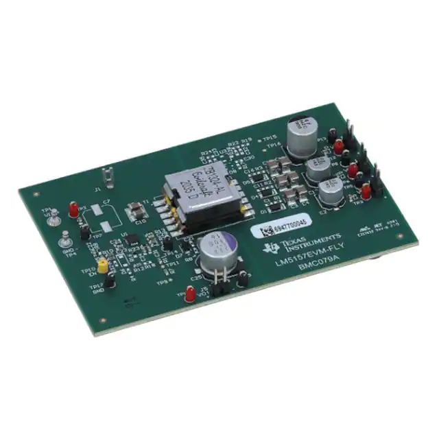
Texas Instruments LM5157EVM-FLY
- Part No.:
- LM5157EVM-FLY
- Manufacturer:
- Texas Instruments
- Package:
- Datasheet:
-
 LM5157EVM-FLY.pdf
- Description:
- EVAL BOARD FOR LM5157
- Quantity:
- Payment:

- Shipping:

Inventory:1,438
Please send an inquiry. Send us your inquiry, and we will respond immediately.
Product details
Overview
LM5157EVM-FLY from Texas Instruments is an evaluation module designed to demonstrate the LM5157-Q1 wide-input non-synchronous flyback controller for multi-rail isolated power conversion in 3-phase inverter gate driver bias supplies. It delivers a regulated 10 V/250 mA main output and three isolated 20 V outputs (75 mA, 75 mA, 150 mA) from 8–16 V input at 250 kHz switching frequency, with peak efficiency >90% and ±1% main output regulation.
For engineers reviewing the LM5157EVM-FLY datasheet, LM5157EVM-FLY test setup, LM5157EVM-FLY application schematic, or LM5157EVM-FLY bill of materials, this module enables rapid validation of cross-regulated flyback topologies, hiccup-mode protection configuration, thermal performance under full load, and Bode plot-based loop stability analysis across input and load variations.
Technical Context
The LM5157EVM-FLY implements a transformer-coupled flyback architecture using the LM5157QRTERQ1 controller IC, supporting adjustable UVLO via external resistors and optional hiccup-mode overcurrent protection enabled by R13/C29. Its standard configuration uses Coilcraft ZB1324-AL transformer with five secondary windings and defined turns ratios (1:1, 1:1.2, 1:2.4) to achieve tight main output regulation and cross-regulation among isolated rails.
Test data confirms stable operation across –40°C to 150°C junction temperature range, with measured ripple <50 mV on Vo1 at 250 mA and <100 mV on Vo4 at 150 mA, while maintaining >91% peak efficiency at 12 V input and full load. The two-layer PCB (3.5 × 2.3 in) integrates all critical components-including polymer capacitors, Schottky rectifiers, and precision resistors-for automotive-grade reliability per AEC-Q200.
Key Specifications
| Parameter | Value and Actual Design Meaning |
|---|---|
| Input Voltage Range | 8 V to 16 V - supports automotive battery rail variations including cold-crank and load-dump conditions. |
| Main Output (Vo1) | 10 V ±1% at 250 mA - tightly regulated primary rail for gate driver logic and biasing. |
| Isolated Outputs (Vo2–Vo4) | Three 20 V rails at 75 mA, 75 mA, 150 mA - cross-regulated secondaries for high-side and low-side gate drive isolation. |
| Switching Frequency | 250 kHz - balances EMI performance, transformer size, and MOSFET conduction losses. |
| Peak Efficiency | >90% at VIN = 12 V, full load - minimizes thermal stress and improves system-level power density. |
| PCB Construction | 2-layer board, 3.5 × 2.3 inches - optimized for layout simplicity, thermal management, and quick prototyping. |
| Protection Features | Hiccup-mode short-circuit protection - configurable via R13/C29 to limit fault energy and enable auto-recovery. |
Availability
LM5157EVM-FLY is available at Aetrix Electronics and suitable for automotive inverter design, industrial motor control development, and isolated auxiliary supply validation requiring stable component supply, documented test procedures, and production-ready reference schematics.
Supply support for LM5157EVM-FLY includes scheduled delivery planning, volume procurement assistance, BOM continuity management, traceable sourcing, and lifecycle availability coordination for OEM customers, industrial embedded developers, connected-device designers, and electronics production programs.
Manufacturer
Texas Instruments is a global semiconductor company specializing in analog, embedded processing, and power management technologies, with leadership in automotive-grade power solutions and evaluation platforms.
The LM5157EVM-FLY belongs to TI's automotive-qualified flyback evaluation module family, engineered specifically to accelerate design-in of isolated bias supplies for IGBT and SiC gate drivers in traction inverters and industrial drives.
FAQ
What is the primary function of the LM5157EVM-FLY?
The LM5157EVM-FLY is an evaluation module that demonstrates the LM5157-Q1 non-synchronous flyback controller for generating multiple isolated output voltages from a single wide-input source. It provides a complete, tested hardware platform to validate performance metrics such as cross-regulation, efficiency, transient response, and thermal behavior-enabling engineers to rapidly assess feasibility before custom design. The LM5157EVM-FLY specifically targets gate driver bias applications in 3-phase inverters.
Can the LM5157EVM-FLY be used with input voltages outside 8–16 V?
No-the LM5157EVM-FLY is validated only for 8 V to 16 V input operation, with absolute maximum input voltage rated at 18 V. Operation below 7.5 V may prevent startup due to UVLO threshold, and exceeding 18 V risks damage to the LM5157QRTERQ1 controller and associated components like the ZB1324-AL transformer and DFLS160-7 rectifier. The LM5157EVM-FLY does not support extended input ranges without hardware modification and revalidation.
How are the three 20-V isolated outputs cross-regulated on the LM5157EVM-FLY?
Cross-regulation on the LM5157EVM-FLY is achieved through transformer coupling and shared feedback control: only the main 10-V output (Vo1) is directly regulated via the FB pin; Vo2, Vo3, and Vo4 derive their voltage from secondary windings with fixed turns ratios relative to the primary, relying on magnetic coupling and load balancing to maintain ±3% regulation across varying loads. Test data (Figures 6-3 to 6-7) confirms this behavior under 10–100% load conditions and 8–16 V input.
Does the LM5157EVM-FLY include thermal imaging data?
Yes-the LM5157EVM-FLY User's Guide includes a thermal image (Figure 6-28) captured at 12 V input and 100% load, showing hotspot temperatures within safe limits for the LM5157QRTERQ1 controller and power components. This data validates the two-layer PCB's thermal performance and confirms junction temperature remains below the 150°C maximum rating under full operational stress, supporting use in demanding automotive environments.
Is hiccup-mode protection enabled by default on the LM5157EVM-FLY?
No-hiccup-mode protection is optional and disabled by default (R13 = 0 Ω). It can be enabled by populating R13 as 62 kΩ and C29 as 47 nF, per Figure 6-25. The LM5157EVM-FLY User's Guide documents both configurations and provides oscilloscope waveforms comparing continuous current-limit versus hiccup recovery behavior, allowing designers to select the appropriate fault-handling strategy for their target application.
LM5157EVM-FLY Specifications
- Product attributes
- Attribute value
- Manufacturer:
- Texas Instruments
- Series:
- -
- Packaging:
- Box
- Product Status:
- Active
- Main Purpose:
- DC/DC Converter
- Outputs and Type:
- 4 Isolated Outputs
- Voltage - Output:
- 8.5 W
- Current - Output:
- 10V, 20V, 20V, 20V
- Voltage - Input:
- 250mA, 150mA, 75mA, 75mA
- Regulator Topology:
- 8V ~ 16V
- Frequency - Switching:
- Flyback
- Contents:
- 250kHz
- Utilized IC / Part:
- Board(s)
- Power - Output:
- LM5157
LM5157EVM-FLY FAQ
1.How can I place an order for LM5157EVM-FLY through Aetrix?
Please submit a Request for Quotation (RFQ) for LM5157EVM-FLY on Aetrix. Our sales agent will provide a competitive quotation and guide you through the order confirmation once you accept the terms.
2.Are the price and stock information for LM5157EVM-FLY reliable?
The price and inventory of LM5157EVM-FLY are updated periodically and may fluctuate due to market conditions. Stock and pricing data are typically refreshed every 24 hours. Quotation validity for LM5157EVM-FLY is usually 5 days.
3.What payment methods are accepted for LM5157EVM-FLY?
We accept Wire Transfer, PayPal, Credit Card, Western Union, MoneyGram, and Escrow for LM5157EVM-FLY transactions.
Note: Certain payment methods may incur a processing fee.
4.How is shipping managed for LM5157EVM-FLY?
LM5157EVM-FLY orders can be shipped via leading logistics carriers, including DHL, UPS, FedEx, TNT, or Registered Mail.
Once your LM5157EVM-FLY order is processed, you will receive an email with the shipment details and tracking number.
Note: Tracking information may take up to 24 hours to appear. Express delivery typically takes 3–5 business days.
5.How can I obtain technical support or documentation for LM5157EVM-FLY?
For technical support, including LM5157EVM-FLY datasheets, pinout diagrams, or application guidance, please contact our engineering support team. They can provide detailed documentation and assistance for your LM5157EVM-FLY requirements.
6.How does Aetrix verify that LM5157EVM-FLY is sourced from the original manufacturer or authorized distributors?
All LM5157EVM-FLY products on Aetrix are procured from qualified distributors and authorized channels. Our dedicated quality assurance team conducts strict verification, including traceability checks and, if necessary, third-party testing. This ensures that LM5157EVM-FLY meets industry standards.
7.What is the process for return or replacement of LM5157EVM-FLY?
All LM5157EVM-FLY units undergo pre-shipment inspection (PSI). If there is an issue with LM5157EVM-FLY, returns or replacements are accepted under the following conditions:
1.Quantity discrepancies, incorrect items, or visible external defects (such as breakage or corrosion), acknowledged by Aetrix.
2.The issue is reported within 90 days of delivery.
3.The LM5157EVM-FLY part is unused and in its original packaging.
Return procedure for LM5157EVM-FLY:
1.Submit a request within 90 days.
2.Obtain a Return Material Authorization (RMA) from Aetrix.
LM5157EVM-FLY Tags
-
DFR0571
DFRobot
-
DFR0379
DFRobot
-
DFR0205
DFRobot

-
1385
Adafruit Industries LLC
-
COM-15208
SparkFun Electronics
-
1944
Adafruit Industries LLC
-
2465
Adafruit Industries LLC
-
DC2468A
Analog Devices Inc.
-
DC2841A
Analog Devices Inc.

-
TPS552892EVM-111
Texas Instruments
-
TPS55289EVM-093
Texas Instruments
-
EPC9158
EPC
Tech Hub

A practical engineering guide to 3.3V and 5V logic compatibility, input thresholds, resistor dividers, translator ICs, MOSFET level shifting, I2C pull-ups, timing limits and power-sequencing risks.

The 74HC595 uses push-pull logic outputs, while the TPIC6B595 uses 50 V open-drain DMOS sinks for higher-power loads. This guide compares timing, current limits, 3.3 V interfacing, load wiring, thermal…

The 74HC595 converts serial data into eight stable parallel outputs. This guide covers pin functions, shift and storage timing, OE and MR behavior, drive-current limits, cascading, voltage compatibilit…

A technical comparison of level-sensitive latches and edge-triggered flip-flops, covering timing windows, setup and hold limits, master–slave operation, time borrowing, race-through, HDL inference and…

A D latch stores one bit while Enable controls when data can pass. This reference covers gate-level operation, truth tables, transparency, setup and hold timing, LE versus OE, common ICs and practical …

An SR latch stores one bit through cross-coupled feedback. This engineering reference covers NOR and NAND implementations, truth tables, forbidden-state recovery, gated operation, switch debouncing, fa…

Latch circuits retain one bit through feedback. This technical reference covers SR and D latches, truth tables, transparency, timing limits, latch-versus-flip-flop behavior, applications and common log…

An engineering guide to LED driver operation, constant-current and constant-voltage outputs, linear and switching topologies, dimming, IC selection, calculations, replacement compatibility, and fault c…

Operational amplifier guide covering op amp basics, feedback, ideal vs real op amps, common configurations, buffer circuits, offset, bias current, gain-bandwidth, slew rate, rail-to-rail limits and sel…

Jumper cables guide covering safe connection order, red and black clamp placement, final ground connection, cable gauge, length, clamp quality, copper vs CCA cables, jump starter comparison and battery…


