
 My Inquiry
 My Account


Texas Instruments LM628N-8
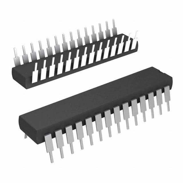
- Part No.:
- LM628N-8
- Manufacturer:
- Texas Instruments
- Category:
- Motor Drivers, Controllers
- Package:
- 28-DIP (0.600", 15.24mm)
- Datasheet:
-
 LM628N-8.pdf
- Description:
- IC MOTOR DRIVER 4.5V-5.5V 28DIP
- Quantity:
- Payment:

- Shipping:

Inventory:3,886
Please send an inquiry. Send us your inquiry, and we will respond immediately.
Product details
Overview
LM628N-8 from Texas Instruments is a dedicated 32-bit precision motion controller IC for closed-loop DC and brushless DC servo systems, featuring programmable digital PID filtering, trapezoidal velocity profile generation, and quadrature encoder interface with index pulse support. It delivers 8-bit parallel DAC output, operates at up to 8 MHz clock frequency, and targets industrial positioning stages, CNC axes, and automated test equipment requiring deterministic real-time motion control.
For engineers reviewing the LM628N-8 datasheet, LM628N-8 pinout, LM628N-8 application, or LM628N-8 equivalent, key selection criteria include its 28-pin PDIP package, 8-bit DAC output mode (not PWM), 1.0–8.0 MHz clock range, −40°C to +85°C operating temperature, and compatibility with incremental encoders delivering A/B/INDEX signals.
Technical Context
The LM628N-8 implements an NMOS-based SDA core processor executing real-time motion algorithms including 32-bit position/velocity/acceleration registers, programmable derivative sampling interval (256 μs minimum at 8 MHz), and fixed 2048/fCLK intervals for proportional/integral terms. Its PID filter uses saturated 16-bit error input, 24-bit integral accumulation (top 16 bits used), and user-configurable 16-bit coefficients (kp, ki, kd) with integration limit (il).
It supports two DAC output configurations: latched 8-bit parallel (Pins 18–25, MSB-to-LSB) or multiplexed 12-bit (using Pins 18–24 plus strobe on Pin 25), both offset-binary coded (0x80 = zero torque). Host communication occurs via 8-bit parallel asynchronous interface (D0–D7, CS, RD, WR, PS) with busy-bit handshaking and real-time interrupt signaling (HI pin).
Key Specifications
| Parameter | Value and Actual Design Meaning |
|---|---|
| Function | Dedicated motion controller IC performing real-time position/velocity/acceleration computation and digital PID compensation for servo loops. |
| Clock Frequency | 1.0–8.0 MHz - determines sampling rate (2048/fCLK ≈ 256 μs at 8 MHz) and max encoder capture rate (1.0 MHz at 8 MHz clock). |
| DAC Output | 8-bit parallel (latched) or 12-bit multiplexed - directly interfaces to external DACs; zero torque at 0x80 (8-bit) or 0x800 (12-bit) offset-binary code. |
| Encoder Interface | Quadrature A/B inputs + INDEX input - provides 4× resolution enhancement; requires ≥8 clock periods per encoder state for valid capture. |
| Operating Temperature | −40°C to +85°C - validated for industrial embedded motion control environments without derating. |
| Supply Voltage | 4.5 V to 5.5 V - single 5-V rail operation compatible with standard TTL/CMOS logic interfaces. |
| Package | 28-pin PDIP (N-suffix) - through-hole mounting; thermal performance supported by copper trace heat sinking per TI guidelines. |
Pinout & Package
LM628N-8 is housed in a 28-pin plastic dual in-line package (PDIP), designated by the "N" suffix. Thermal management relies on PCB copper area surrounding leads and ground plane conduction per TI's power dissipation guidance (605 mW max at TA ≤85°C).
| Pin/Terminal | Circuit Role | Design Meaning |
|---|---|---|
| 1 | Index (IN) Input | Optional encoder index pulse input; must be tied high if unused; triggers index position capture when low with Pins 2 & 3. |
| 2, 3 | Encoder A, B Inputs | Quadrature phase signals; define motor direction and increment/decrement position register; require ≥8 clock periods per state. |
| 4–11 | Host I/O Port D0–D7 | Bi-directional 8-bit data bus for command/data transfer; controlled by CS, RD, WR, and PS signals. |
| 12 | Chip Select (CS) | Active-low enable for host read/write operations; must be asserted before RD or WR strobes. |
| 13 | Read (RD) | Active-low strobe to read status byte (PS=low) or data words (PS=high); initiates synchronous data fetch. |
| 14 | GND | Power-supply return reference; critical for noise immunity in analog feedback paths and DAC output stability. |
| 15 | Write (WR) | Active-low strobe to write commands (PS=low) or data words (PS=high); latches data on rising edge. |
| 16 | Port Select (PS) | Selects command port (low) or data port (high); determines whether D0–D7 carries commands/status or trajectory/filter data. |
| 17 | Host Interrupt (HI) | Active-high open-drain output signaling interrupt conditions (e.g., index capture, error threshold exceeded). |
| 18–25 | DAC0–DAC7 Output | 8-bit latched parallel DAC output port (MSB=Pin 18, LSB=Pin 25); outputs 0x80 at reset to center 8-bit DAC. |
| 26 | Clock (CLK) | CMOS-compatible input accepting 1–8 MHz square wave; drives internal timing for sampling, filtering, and encoder decoding. |
| 27 | Reset (RST) | Active-low, edge-triggered reset; requires ≥8 clock periods low; initializes registers, zeros filters, sets DAC to zero-torque code. |
| 28 | VDD | +5 V supply input; must be decoupled locally with 0.1 μF ceramic capacitor; tolerates 4.5–5.5 V per operating ratings. |
Key Features
| Feature | Design Value |
|---|---|
| 32-bit position/velocity/acceleration registers | Enables sub-micron positioning resolution over ±1.07 billion counts with 16-bit fractional scaling for velocity/acceleration. |
| Programmable digital PID filter | Supports full 16-bit kp/ki/kd coefficient loading and integration limit (il) to stabilize diverse mechanical loads without external tuning components. |
| Trapezoidal velocity profile generator | Permits dynamic on-the-fly updates of target position, max velocity, and acceleration during motion-critical for synchronized multi-axis moves. |
| Quadrature encoder interface with index support | Delivers 4× effective encoder line resolution and absolute homing via index pulse capture, eliminating need for external counters or FPGA logic. |
| 8-bit parallel DAC output (LM628-specific) | Direct connection to off-chip DACs without multiplexing overhead; avoids timing complexity and external latch requirements of 12-bit mode. |
Applications
| Industrial CNC Axis Control | Automated Test Equipment Positioning |
|---|---|
|
Use Scenario: Precise linear actuator control in milling machine X/Y/Z axes using 500-line incremental encoder feedback and H-bridge amplifier. IC Role / Device Role / Timing Role: Real-time trajectory generation and PID compensation engine; computes position error every 256 μs and updates DAC output synchronously with encoder state changes. Use Value: Eliminates host CPU motion computation load; enables smooth trapezoidal moves with <100 μs jitter and repeatable ±1-count positioning accuracy over 100-revolution travel. |
Use Scenario: High-speed probe positioning in semiconductor wafer testers, where rapid settle-to-position (<50 ms) and repeatability are mandatory. IC Role / Device Role / Timing Role: Dedicated motion coprocessor managing closed-loop position control independently of test sequencer; handles encoder interrupts and DAC updates autonomously. Use Value: Reduces system latency by offloading motion math; achieves 0.01% velocity regulation during ramp phases using programmable derivative sampling interval. |
| Lab Automation Robotic Arm Joint | Print Head Carriage Control |
|
Use Scenario: 4-degree-of-freedom robotic arm joint with brushless DC motor, optical encoder, and current-mode amplifier in biomedical instrumentation. IC Role / Device Role / Timing Role: Servo controller executing position-mode motion profiles while maintaining zero static error via integral windup limiting (il parameter). Use Value: Guarantees zero steady-state position error under constant payload torque; supports dynamic re-targeting mid-move without overshoot via LPEI/LPES interrupt handling. |
Use Scenario: Bidirectional carriage movement in wide-format inkjet printers using belt-driven mechanism and 200-line encoder. IC Role / Device Role / Timing Role: Motion timing master generating precise velocity ramps and coordinating start/stop with print data streaming via parallel host interface. Use Value: Enables consistent dot placement accuracy (<±2 μm) across full print swath by eliminating host-induced timing jitter in velocity profile execution. |
Equivalent & Alternatives
The following parts are listed as comparable options for similar motion controller applications.
| Alternative Part | Technical Difference | Application Difference | Selection Advice |
|---|---|---|---|
| LM629N-8 | Replaces 8-bit DAC output with 8-bit sign-magnitude PWM output on Pins 18–19; no DAC0–DAC7 parallel port functionality. | Suitable for direct H-switch driving without external DAC; incompatible with existing LM628N-8 DAC-based amplifier designs. | Select LM629N-8 only when replacing discrete DAC + op-amp stage with integrated PWM motor drive; requires PCB layout change for output routing. |
| MC33035 | Brushless DC motor controller with built-in commutation logic and 3-phase gate drive; lacks 32-bit trajectory generator and quadrature decoder. | Targets sensorless or Hall-effect-commutated BLDC motors; not suitable for high-resolution encoder-based positioning tasks. | Choose MC33035 for cost-sensitive BLDC fan/pump control; avoid for precision position servo applications requiring LM628N-8's computational features. |
Compared with LM629N-8, LM628N-8 provides direct DAC interfacing essential for analog amplifier topologies, while MC33035 offers integrated power-stage control but omits encoder-based closed-loop positioning capability entirely-making LM628N-8 irreplaceable for high-accuracy motion systems requiring software-defined trajectories and PID tuning.
Availability
LM628N-8 is available at Aetrix Electronics and suitable for industrial CNC axis control, automated test equipment positioning, and lab automation robotic arm joint applications requiring stable component supply across extended production lifecycles.
Supply support for LM628N-8 includes scheduled delivery planning, volume procurement assistance, BOM continuity management, traceable sourcing, and lifecycle availability coordination for OEM customers, industrial embedded developers, connected-device designers, and electronics production programs.
Manufacturer
Texas Instruments is a global semiconductor leader specializing in analog, embedded processing, and high-reliability components for industrial, automotive, and communications markets.
The LM628 product line was designed specifically for deterministic, real-time digital motion control in resource-constrained embedded systems-enabling precise servo loop execution without host CPU intervention.
FAQ
What is the maximum encoder quadrature capture rate supported by the LM628N-8?
The LM628N-8 supports a maximum encoder-state capture rate of 1.0 MHz when operated at its 8 MHz clock frequency. This is derived from the requirement that each encoder A/B state must persist for a minimum of 8 clock periods-yielding 8,000,000 ÷ 8 = 1,000,000 state transitions per second. The LM628N-8 achieves 4× resolution enhancement over physical encoder lines due to its quadrature decoding method, making it suitable for high-speed positioning applications where fine-grained feedback is critical.
Does the LM628N-8 support both 8-bit and 12-bit DAC output modes?
Yes, the LM628N-8 supports both output configurations via software command: PORT8 (0x05) selects latched 8-bit parallel output on Pins 18–25, while PORT12 (0x06) enables multiplexed 12-bit output using Pins 18–24 and strobe on Pin 25. The LM628N-8 defaults to 8-bit mode after reset (outputting 0x80), and the selected mode persists until reconfigured. Note that LM629 variants do not support either DAC mode-they provide PWM outputs instead.
How does the LM628N-8 handle real-time motion parameter updates during active movement?
The LM628N-8 permits dynamic updates to target position, maximum velocity, and acceleration parameters while motion is in progress-via LTRJ command-enabling synchronized multi-axis trajectories and responsive error recovery. Commands like STT (start motion) and UDF (update filter) execute without halting motion, and interrupt conditions (e.g., index capture or position error threshold breach) are signaled immediately on the HI pin. This real-time adaptability is central to the LM628N-8's role in high-performance motion systems.
What is the function of the derivative sampling interval in the LM628N-8 PID filter?
The derivative sampling interval in the LM628N-8 is programmable from 2048/fCLK to (2048 × 256)/fCLK in steps of 2048/fCLK, yielding 256 μs to 65,536 μs at 8 MHz. It decouples derivative term evaluation from the main control loop sample rate, allowing damping behavior to be tuned independently for mechanical systems with varying inertia and resonance-improving stability in low-velocity or high-inertia applications without compromising proportional/integral responsiveness.
Is the LM628N-8 pin-compatible with the LM629N-8?
No, the LM628N-8 and LM629N-8 are not pin-compatible. While both use the same 28-pin PDIP package and share identical pin assignments for power, clock, reset, host interface, and encoder inputs, their output pins differ fundamentally: LM628N-8 uses Pins 18–25 for 8-/12-bit DAC data, whereas LM629N-8 repurposes Pins 18–19 for PWM sign/magnitude signals and leaves Pins 20–25 unused. Direct replacement requires PCB redesign and firmware adaptation.
LM628N-8 Specifications
- Product attributes
- Attribute value
- Manufacturer:
- Texas Instruments
- Series:
- -
- Package/Case:
- 28-DIP (0.600", 15.24mm)
- Packaging:
- Tube
- Product Status:
- Obsolete
- Motor Type - Stepper:
- -
- Motor Type - AC, DC:
- Brushless DC (BLDC) Servo, Brushed DC Servo
- Function:
- Controller - Commutation, Direction Management
- Output Configuration:
- Pre-Driver - Half Bridge (4)
- Interface:
- Parallel
- Technology:
- -
- Step Resolution:
- -
- Applications:
- General Purpose
- Current - Output:
- -
- Voltage - Supply:
- 4.5V ~ 5.5V
- Voltage - Load:
- -
- Operating Temperature:
- -40°C ~ 85°C (TA)
- Grade:
- -
- Qualification:
- -
- Mounting Type:
- Through Hole
- Supplier Device Package:
- 28-PDIP
LM628N-8 FAQ
1.How can I place an order for LM628N-8 through Aetrix?
Please submit a Request for Quotation (RFQ) for LM628N-8 on Aetrix. Our sales agent will provide a competitive quotation and guide you through the order confirmation once you accept the terms.
2.Are the price and stock information for LM628N-8 reliable?
The price and inventory of LM628N-8 are updated periodically and may fluctuate due to market conditions. Stock and pricing data are typically refreshed every 24 hours. Quotation validity for LM628N-8 is usually 5 days.
3.What payment methods are accepted for LM628N-8?
We accept Wire Transfer, PayPal, Credit Card, Western Union, MoneyGram, and Escrow for LM628N-8 transactions.
Note: Certain payment methods may incur a processing fee.
4.How is shipping managed for LM628N-8?
LM628N-8 orders can be shipped via leading logistics carriers, including DHL, UPS, FedEx, TNT, or Registered Mail.
Once your LM628N-8 order is processed, you will receive an email with the shipment details and tracking number.
Note: Tracking information may take up to 24 hours to appear. Express delivery typically takes 3–5 business days.
5.How can I obtain technical support or documentation for LM628N-8?
For technical support, including LM628N-8 datasheets, pinout diagrams, or application guidance, please contact our engineering support team. They can provide detailed documentation and assistance for your LM628N-8 requirements.
6.How does Aetrix verify that LM628N-8 is sourced from the original manufacturer or authorized distributors?
All LM628N-8 products on Aetrix are procured from qualified distributors and authorized channels. Our dedicated quality assurance team conducts strict verification, including traceability checks and, if necessary, third-party testing. This ensures that LM628N-8 meets industry standards.
7.What is the process for return or replacement of LM628N-8?
All LM628N-8 units undergo pre-shipment inspection (PSI). If there is an issue with LM628N-8, returns or replacements are accepted under the following conditions:
1.Quantity discrepancies, incorrect items, or visible external defects (such as breakage or corrosion), acknowledged by Aetrix.
2.The issue is reported within 90 days of delivery.
3.The LM628N-8 part is unused and in its original packaging.
Return procedure for LM628N-8:
1.Submit a request within 90 days.
2.Obtain a Return Material Authorization (RMA) from Aetrix.
LM628N-8 Tags

-
DRV2603RUNR
Texas Instruments

-
DRV8837CDSGR
Texas Instruments

-
DRV8837DSGR
Texas Instruments
-
DRV8838DSGR
Texas Instruments

-
DRV8839DSSR
Texas Instruments

-
EMC2301-1-ACZL-TR
Microchip Technology
-
DRV8231ADSGR
Texas Instruments

-
EMC2302-2-AIZL-TR
Microchip Technology

-
DRV8800PWPR
Texas Instruments
-
DRV8835DSSR
Texas Instruments

-
EMC2303-1-KP-TR
Microchip Technology

-
DRV8876PWPR
Texas Instruments
Tech Hub

A practical engineering guide to 3.3V and 5V logic compatibility, input thresholds, resistor dividers, translator ICs, MOSFET level shifting, I2C pull-ups, timing limits and power-sequencing risks.

The 74HC595 uses push-pull logic outputs, while the TPIC6B595 uses 50 V open-drain DMOS sinks for higher-power loads. This guide compares timing, current limits, 3.3 V interfacing, load wiring, thermal…

The 74HC595 converts serial data into eight stable parallel outputs. This guide covers pin functions, shift and storage timing, OE and MR behavior, drive-current limits, cascading, voltage compatibilit…

A technical comparison of level-sensitive latches and edge-triggered flip-flops, covering timing windows, setup and hold limits, master–slave operation, time borrowing, race-through, HDL inference and…

A D latch stores one bit while Enable controls when data can pass. This reference covers gate-level operation, truth tables, transparency, setup and hold timing, LE versus OE, common ICs and practical …

An SR latch stores one bit through cross-coupled feedback. This engineering reference covers NOR and NAND implementations, truth tables, forbidden-state recovery, gated operation, switch debouncing, fa…

Latch circuits retain one bit through feedback. This technical reference covers SR and D latches, truth tables, transparency, timing limits, latch-versus-flip-flop behavior, applications and common log…

An engineering guide to LED driver operation, constant-current and constant-voltage outputs, linear and switching topologies, dimming, IC selection, calculations, replacement compatibility, and fault c…

Operational amplifier guide covering op amp basics, feedback, ideal vs real op amps, common configurations, buffer circuits, offset, bias current, gain-bandwidth, slew rate, rail-to-rail limits and sel…

Jumper cables guide covering safe connection order, red and black clamp placement, final ground connection, cable gauge, length, clamp quality, copper vs CCA cables, jump starter comparison and battery…


