
 My Inquiry
 My Account


Texas Instruments LM629N-8/NOPB
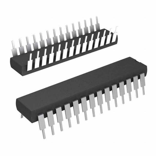
- Part No.:
- LM629N-8/NOPB
- Manufacturer:
- Texas Instruments
- Category:
- Motor Drivers, Controllers
- Package:
- 28-DIP (0.600", 15.24mm)
- Datasheet:
-
 LM629N-8/NOPB.pdf
- Description:
- IC MOTOR DRIVER 4.5V-5.5V 28DIP
- Quantity:
- Payment:

- Shipping:

Inventory:3,849
Please send an inquiry. Send us your inquiry, and we will respond immediately.
Product details
Overview
LM629N-8/NOPB from Texas Instruments is a dedicated 8-bit PWM-output motion controller IC for brushless DC and servo motor systems, featuring 32-bit position/velocity/acceleration registers, programmable digital PID filtering with 16-bit coefficients, internal trapezoidal velocity profile generation, and quadrature encoder interface with index pulse support. It operates at up to 8 MHz clock frequency and delivers sign-magnitude PWM output for direct H-bridge drive in industrial positioning systems.
For engineers reviewing the LM629N-8/NOPB datasheet, LM629N-8/NOPB pinout, LM629N-8/NOPB application, or LM629N-8/NOPB equivalent, key selection considerations include its 8-bit PWM output architecture (vs. LM628's DAC), 28-pin PDIP package, −40°C to +85°C operating range, real-time interrupt support, and compatibility with incremental encoders delivering quadrature A/B and index signals.
Technical Context
The LM629N-8/NOPB implements a fixed-function SDA-core motion processor executing real-time trajectory computation and digital PID control at user-defined sampling intervals. Its derivative term sampling interval is programmable from 256 μs to 65.536 ms (for 8 MHz clock), while proportional and integral terms sample every 256 μs. The device uses saturated 16-bit error arithmetic, 24-bit integral accumulation (top 16 bits used), and offset-binary 8-bit PWM output mapping (sign on Pin 18, magnitude on Pin 19).
It supports two operational modes - position mode (trapezoidal profile tracking) and velocity mode (constant-speed motion) - with all trajectory parameters stored as 32-bit signed integers (position) or 16-bit fractional values (velocity/acceleration). Host communication occurs via 8-bit parallel asynchronous interface with chip-select, port-select, read, and write strobes, and status polling via busy-bit flag.
Key Specifications
| Parameter | Value and Actual Design Meaning |
|---|---|
| Output Type | 8-bit sign-magnitude PWM: Pin 18 = sign (active-high), Pin 19 = magnitude (0–255), enables direct H-switch control without external DAC. |
| Max Clock Frequency | 8.0 MHz: Enables 256 μs base sampling interval for PID and trajectory calculations; supports encoder-state capture up to 1.0 MHz. |
| Position Resolution | 32-bit signed count range: −1,073,741,824 to +1,073,741,823 counts - sufficient for sub-micron precision over multi-meter travel with high-line encoders. |
| PID Filter Coefficients | 16-bit programmable kp, ki, kd: ki scaled with 8-bit right-shift for stable low-gain integration; derivative sampling independently configurable. |
| Operating Temperature | −40°C to +85°C: Validated for industrial embedded motion control environments including factory automation and CNC peripherals. |
| Supply Voltage | 4.5 V to 5.5 V: Compatible with standard 5 V logic rails; 110 mA typical supply current at 6 MHz ensures predictable thermal design in PDIP package. |
Pinout & Package
LM629N-8/NOPB is housed in a 28-pin plastic dual in-line package (PDIP), with lead finish NiPdAu and RoHS-compliant /NOPB marking. Thermal performance relies on PCB copper area acting as heatsink due to solid-copper lead frame construction.
| Pin | Circuit Role | Design Meaning |
|---|---|---|
| 1 | Index (IN) Input | Optional encoder index pulse input; must be pulled high if unused; triggers index position capture when Pins 1–3 are simultaneously low. |
| 2, 3 | Encoder A/B Inputs | Quadrature phase inputs; Pin 2 leads Pin 3 by 90° in forward rotation; minimum dwell time = 8 clock periods (320 ns @ 8 MHz). |
| 4–11 | Host Data Bus (D0–D7) | Bi-directional 8-bit parallel interface for command/data transfer; synchronized by CS, PS, RD, WR signals. |
| 12 | Chip Select (CS) | Active-low enable for host read/write operations; must be asserted before PS/RD/WR strobes. |
| 13 | Read (RD) | Active-low strobe to read status byte (PS = low) or data words (PS = high); initiates Hi-Z after T12 = 180 ns. |
| 14 | GND | Power-supply return; serves as reference for all analog and digital signals including encoder and PWM outputs. |
| 15 | Write (WR) | Active-low strobe to write commands (PS = low) or data words (PS = high); latches data on rising edge. |
| 16 | Port Select (PS) | Selects command port (low) for status/commands or data port (high) for 16-bit word transfers; controls internal register mapping. |
| 17 | Host Interrupt (HI) | Active-high open-drain output signaling interrupt conditions (e.g., index capture, error threshold breach, breakpoint hit). |
| 18 | PWM Sign Output | Active-high sign bit for H-bridge direction control; complements magnitude signal on Pin 19 to define torque polarity. |
| 19 | PWM Magnitude Output | 8-bit PWM duty-cycle output (0–100%); zero = 0x00 (off), full scale = 0xFF; maps directly to H-bridge gate drive timing. |
| 26 | CLK Input | CMOS-compatible clock input; accepts 1–8 MHz crystal or oscillator; determines all timing intervals including encoder sampling and PID execution. |
| 27 | Reset (RST) | Active-low, edge-triggered reset; requires ≥8 clock periods low; initializes position to zero, clears filters, masks SBPA/SBPR interrupts. |
| 28 | VDD | +5 V power supply; regulated 4.5–5.5 V range ensures stable operation of internal NMOS logic and output drivers. |
Key Features
| Feature | Design Value |
|---|---|
| Trapezoidal Velocity Profile Generator | Hardware-accelerated real-time trajectory engine supporting dynamic updates to target position, max velocity, and acceleration during motion - eliminates host CPU burden in closed-loop positioning. |
| Programmable Derivative Sampling Interval | Configurable from 256 μs to 65.536 ms in 256 μs steps; allows optimal derivative term tuning for mechanical loads with widely varying time constants (e.g., lightweight stages vs. heavy gantries). |
| Quadrature Encoder Interface with Index Support | Four-times encoder line resolution via state-transition counting; index pulse capture enables absolute position homing without external microcontroller intervention. |
| Real-time Host Interrupts | Six interrupt sources (SBPA, SBPR, LPEI, LPES, SIP, HI) with maskable priority; enables deterministic response to motion events without polling overhead. |
| 8-bit Sign-Magnitude PWM Output | Dedicated Pin 18 (sign) and Pin 19 (magnitude) eliminate need for external logic or DAC; simplifies interface to discrete H-bridge or integrated motor drivers like L298 or DRV8871. |
Applications
| Industrial CNC Axis Control | Automated Test Equipment Positioning |
|---|---|
Use Scenario: Precise linear actuator control in benchtop CNC mills using 500-line optical encoders and bipolar stepper-to-servo conversion. IC Role / Device Role / Timing Role: LM629N-8/NOPB executes real-time trapezoidal profiling and PID correction at 256 μs intervals, synchronizing PWM output to encoder feedback for sub-10 μm repeatability. Use Value: Reduces host processor load by offloading motion math; enables smooth acceleration/deceleration without jerk-induced vibration in high-inertia axes. |
Use Scenario: Z-axis height adjustment in automated optical inspection systems requiring repeatable 0.1 mm positioning across thermal cycles. IC Role / Device Role / Timing Role: LM629N-8/NOPB maintains position hold via integral windup control and detects loss-of-step via LPEI interrupt, triggering system fault reporting. Use Value: Eliminates need for external position controller FPGA; built-in index capture ensures absolute position recovery after power loss. |
| Robotic Joint Actuation | Lab Automation Liquid Handling |
Use Scenario: Servo-driven elbow joint in collaborative robot arm using 2000-line encoder and brushed DC motor with H-bridge driver. IC Role / Device Role / Timing Role: LM629N-8/NOPB generates velocity-limited trajectories and applies sign-magnitude PWM to drive TI DRV8871 H-bridge, with real-time error monitoring. Use Value: Enables safe, compliant motion through programmable position error thresholds and immediate stop-on-error (LPES) response within 1.5 ms. |
Use Scenario: Multi-channel pipette carriage movement in high-throughput ELISA plate handlers requiring coordinated multi-axis moves with synchronized start/stop. IC Role / Device Role / Timing Role: LM629N-8/NOPB manages independent axis profiles and reports real position (RDRP) and velocity (RDRV) via host I/O for inter-axis synchronization. Use Value: Provides deterministic motion timing without host timing jitter; supports "on-the-fly" parameter updates for adaptive dispensing sequences. |
Equivalent & Alternatives
The following parts are listed as comparable options for similar motion controller applications.
| Alternative Part | Technical Difference | Application Difference | Selection Advice |
|---|---|---|---|
| LM629M-8/NOPB | SOIC-24 surface-mount package; identical electrical functionality and pinout mapping (with renumbered pins per Figure 2); same 8 MHz clock rating and PWM output structure. | Preferred for space-constrained PCBs and automated assembly; requires different footprint and thermal layout vs. PDIP. | Select LM629M-8/NOPB when board area or reflow compatibility is critical; verify encoder interface trace lengths meet SOIC signal integrity requirements. |
| LM628N-8/NOPB | Same 28-pin PDIP package and clock rating, but provides 8-bit or 12-bit parallel DAC output instead of PWM; lacks sign/magnitude PWM pins (18/19) and uses DAC0–DAC7 (Pins 18–25). | Requires external DAC and power amplifier; suitable where analog voltage drive (e.g., to LM675 op-amp) is preferred over PWM switching. | Choose LM628N-8/NOPB only when interfacing to legacy analog motor drivers; LM629N-8/NOPB offers lower BOM count for H-bridge-based designs. |
Compared with LM629M-8/NOPB, LM629N-8/NOPB trades surface-mount manufacturability for through-hole prototyping ease and higher thermal mass; compared with LM628N-8/NOPB, it replaces DAC dependency with integrated PWM drive - reducing component count and eliminating DAC settling-time latency in high-bandwidth loops.
Availability
LM629N-8/NOPB is available at Aetrix Electronics and suitable for industrial CNC axis control, automated test equipment positioning, robotic joint actuation, and lab automation liquid handling requiring stable component supply across long production lifecycles.
Supply support for LM629N-8/NOPB includes scheduled delivery planning, volume procurement assistance, BOM continuity management, traceable sourcing, and lifecycle availability coordination for OEM customers, industrial embedded developers, connected-device designers, and electronics production programs.
Manufacturer
Texas Instruments is a global semiconductor leader specializing in analog, embedded processing, and high-reliability components for industrial, automotive, and communications markets.
The LM629N-8/NOPB belongs to TI's precision motion controller product line, designed specifically to offload real-time trajectory generation and digital PID control from host microcontrollers in cost-sensitive, high-volume servo systems.
FAQ
What is the function of Pin 18 and Pin 19 on the LM629N-8/NOPB?
Pin 18 is the PWM sign output and Pin 19 is the PWM magnitude output of the LM629N-8/NOPB. Together they form an 8-bit sign-magnitude PWM signal: Pin 18 is active-high for positive torque and low for negative torque, while Pin 19 delivers an 8-bit duty-cycle value (0x00–0xFF) defining motor drive strength. This architecture enables direct connection to H-bridge drivers without external DAC or logic translation, distinguishing LM629N-8/NOPB from the DAC-output LM628 family.
Does the LM629N-8/NOPB support real-time parameter updates during motion?
Yes, the LM629N-8/NOPB supports real-time updates to key motion parameters during active movement. Commands such as STT (Start Motion), LTRJ (Load Trajectory), and UDF (Update Filter) allow dynamic changes to target position, maximum velocity, acceleration, and PID coefficients without halting motion. The device confirms successful execution via status byte transitions (e.g., from 0x00 to 0x84), and all updates occur within deterministic timing windows defined by the 256 μs base sampling interval.
How does the LM629N-8/NOPB interface with quadrature encoders?
The LM629N-8/NOPB interfaces with quadrature encoders via Pins 2 (A) and 3 (B), which accept differential or single-ended TTL-level phase signals. It decodes transitions to achieve 4× line resolution and enforces a minimum dwell time of 8 clock periods per state (320 ns at 8 MHz). An optional index pulse on Pin 1 enables absolute position homing. The device internally tracks position error against desired trajectory and feeds this into its PID filter - all without host CPU involvement.
What is the maximum encoder input frequency supported by the LM629N-8/NOPB?
The LM629N-8/NOPB supports a maximum quadrature encoder input frequency of 1.0 MHz when operated with an 8.0 MHz clock. This limit arises from the requirement that each encoder state must persist for at least 8 clock periods (8 × 125 ns = 1.0 μs), enabling reliable state transition detection. At lower clock frequencies (e.g., 6 MHz), the maximum supported encoder rate drops to 750 kHz. The device does not support RS-422 or differential encoder inputs natively - external line receivers may be required for long cable runs.
Can the LM629N-8/NOPB operate with a 3.3 V host interface?
No, the LM629N-8/NOPB requires a 5 V host interface. Its input logic thresholds are specified as VIH = 2.0 V minimum and VIL = 0.8 V maximum, but the device itself operates from a 4.5–5.5 V VDD supply and drives outputs at TTL-compatible levels. Connecting 3.3 V host signals directly risks violating the minimum VIH specification under worst-case voltage tolerances and may cause unreliable command recognition. Level-shifting circuitry is required for interoperability with 3.3 V microcontrollers.
LM629N-8/NOPB Specifications
- Product attributes
- Attribute value
- Manufacturer:
- Texas Instruments
- Series:
- -
- Package/Case:
- 28-DIP (0.600", 15.24mm)
- Packaging:
- Tube
- Product Status:
- Obsolete
- Motor Type - Stepper:
- -
- Motor Type - AC, DC:
- Brushless DC (BLDC) Servo, Brushed DC Servo
- Function:
- Controller - Commutation, Direction Management
- Output Configuration:
- Pre-Driver - Half Bridge (4)
- Interface:
- Parallel
- Technology:
- -
- Step Resolution:
- -
- Applications:
- General Purpose
- Current - Output:
- -
- Voltage - Supply:
- 4.5V ~ 5.5V
- Voltage - Load:
- -
- Operating Temperature:
- -40°C ~ 85°C (TA)
- Grade:
- -
- Qualification:
- -
- Mounting Type:
- Through Hole
- Supplier Device Package:
- 28-DIP
LM629N-8/NOPB FAQ
1.How can I place an order for LM629N-8/NOPB through Aetrix?
Please submit a Request for Quotation (RFQ) for LM629N-8/NOPB on Aetrix. Our sales agent will provide a competitive quotation and guide you through the order confirmation once you accept the terms.
2.Are the price and stock information for LM629N-8/NOPB reliable?
The price and inventory of LM629N-8/NOPB are updated periodically and may fluctuate due to market conditions. Stock and pricing data are typically refreshed every 24 hours. Quotation validity for LM629N-8/NOPB is usually 5 days.
3.What payment methods are accepted for LM629N-8/NOPB?
We accept Wire Transfer, PayPal, Credit Card, Western Union, MoneyGram, and Escrow for LM629N-8/NOPB transactions.
Note: Certain payment methods may incur a processing fee.
4.How is shipping managed for LM629N-8/NOPB?
LM629N-8/NOPB orders can be shipped via leading logistics carriers, including DHL, UPS, FedEx, TNT, or Registered Mail.
Once your LM629N-8/NOPB order is processed, you will receive an email with the shipment details and tracking number.
Note: Tracking information may take up to 24 hours to appear. Express delivery typically takes 3–5 business days.
5.How can I obtain technical support or documentation for LM629N-8/NOPB?
For technical support, including LM629N-8/NOPB datasheets, pinout diagrams, or application guidance, please contact our engineering support team. They can provide detailed documentation and assistance for your LM629N-8/NOPB requirements.
6.How does Aetrix verify that LM629N-8/NOPB is sourced from the original manufacturer or authorized distributors?
All LM629N-8/NOPB products on Aetrix are procured from qualified distributors and authorized channels. Our dedicated quality assurance team conducts strict verification, including traceability checks and, if necessary, third-party testing. This ensures that LM629N-8/NOPB meets industry standards.
7.What is the process for return or replacement of LM629N-8/NOPB?
All LM629N-8/NOPB units undergo pre-shipment inspection (PSI). If there is an issue with LM629N-8/NOPB, returns or replacements are accepted under the following conditions:
1.Quantity discrepancies, incorrect items, or visible external defects (such as breakage or corrosion), acknowledged by Aetrix.
2.The issue is reported within 90 days of delivery.
3.The LM629N-8/NOPB part is unused and in its original packaging.
Return procedure for LM629N-8/NOPB:
1.Submit a request within 90 days.
2.Obtain a Return Material Authorization (RMA) from Aetrix.
LM629N-8/NOPB Tags

-
DRV2603RUNR
Texas Instruments

-
DRV8837CDSGR
Texas Instruments

-
DRV8837DSGR
Texas Instruments
-
DRV8838DSGR
Texas Instruments

-
DRV8839DSSR
Texas Instruments

-
EMC2301-1-ACZL-TR
Microchip Technology
-
DRV8231ADSGR
Texas Instruments

-
EMC2302-2-AIZL-TR
Microchip Technology

-
DRV8800PWPR
Texas Instruments
-
DRV8835DSSR
Texas Instruments

-
EMC2303-1-KP-TR
Microchip Technology

-
DRV8876PWPR
Texas Instruments
Tech Hub

A practical engineering guide to 3.3V and 5V logic compatibility, input thresholds, resistor dividers, translator ICs, MOSFET level shifting, I2C pull-ups, timing limits and power-sequencing risks.

The 74HC595 uses push-pull logic outputs, while the TPIC6B595 uses 50 V open-drain DMOS sinks for higher-power loads. This guide compares timing, current limits, 3.3 V interfacing, load wiring, thermal…

The 74HC595 converts serial data into eight stable parallel outputs. This guide covers pin functions, shift and storage timing, OE and MR behavior, drive-current limits, cascading, voltage compatibilit…

A technical comparison of level-sensitive latches and edge-triggered flip-flops, covering timing windows, setup and hold limits, master–slave operation, time borrowing, race-through, HDL inference and…

A D latch stores one bit while Enable controls when data can pass. This reference covers gate-level operation, truth tables, transparency, setup and hold timing, LE versus OE, common ICs and practical …

An SR latch stores one bit through cross-coupled feedback. This engineering reference covers NOR and NAND implementations, truth tables, forbidden-state recovery, gated operation, switch debouncing, fa…

Latch circuits retain one bit through feedback. This technical reference covers SR and D latches, truth tables, transparency, timing limits, latch-versus-flip-flop behavior, applications and common log…

An engineering guide to LED driver operation, constant-current and constant-voltage outputs, linear and switching topologies, dimming, IC selection, calculations, replacement compatibility, and fault c…

Operational amplifier guide covering op amp basics, feedback, ideal vs real op amps, common configurations, buffer circuits, offset, bias current, gain-bandwidth, slew rate, rail-to-rail limits and sel…

Jumper cables guide covering safe connection order, red and black clamp placement, final ground connection, cable gauge, length, clamp quality, copper vs CCA cables, jump starter comparison and battery…


