
 My Inquiry
 My Account


Texas Instruments LM98714CCMT
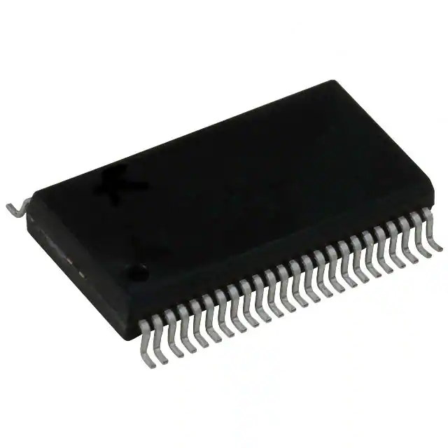
- Part No.:
- LM98714CCMT
- Manufacturer:
- Texas Instruments
- Category:
- Analog Front End (AFE)
- Package:
- 48-TFSOP (0.240", 6.10mm Width)
- Datasheet:
-
 LM98714CCMT.pdf
- Description:
- IC AFE 3 CHAN 16BIT 48TSSOP
- Quantity:
- Payment:

- Shipping:

Inventory:4,617
Please send an inquiry. Send us your inquiry, and we will respond immediately.
Product details
Overview
LM98714CCMT from Texas Instruments is a three-channel, 16-bit, 45 MSPS analog front end (AFE) with integrated CCD/CIS sensor timing generator, LVDS/CMOS output interface, and independent CDS/S/H processing per channel - designed for high-fidelity color image capture in flatbed scanners and MFPs. It supports 0.7–7.84× programmable gain, ±9-bit analog offset correction, and digital black level loops per channel.
For engineers reviewing the LM98714CCMT datasheet, LM98714CCMT pinout, LM98714CCMT application, or LM98714CCMT equivalent, this device serves as a complete AFE solution requiring precise pixel-rate synchronization, multi-channel DC offset calibration, and low-noise 16-bit digitization at up to 45 MSPS with configurable LVDS or CMOS output formatting.
Technical Context
The LM98714CCMT implements a fully differential signal path with Correlated Double Sampling (CDS) for CCD sensors or Sample-and-Hold (S/H) for CIS/CMOS sensors, each with independent 8-bit PGA gain control (256 steps) and ±9-bit analog DAC offset correction. Its internal timing generator produces up to ten configurable digital outputs (CLK1–CLK10, SH) for sensor clocking and transfer control.
It operates in three selectable AFE modes: Mode 3 (3-channel synchronous sampling at 15 MSPS/channel), Mode 2 (2-channel at 22.5 MSPS/channel), and Mode 1 (1-channel sequential line sampling at 30 MSPS), all synchronized to a single 45 MSPS ADC core with LVDS or CMOS parallel output formatting.
Key Specifications
| Parameter | Value and Actual Design Meaning |
|---|---|
| ADC Resolution | 16-bit - delivers full dynamic range for professional-grade color scanner digitization without dithering or interpolation. |
| Max Sampling Rate | 45 MSPS - enables real-time digitization of high-resolution RGB linescans at >600 DPI with minimal latency. |
| Input Channels | 3 independent analog inputs (OSR/OSG/OSB) - supports simultaneous RGB capture from tri-linear CCD arrays. |
| PGA Gain Range | 0.7× to 7.84× - accommodates wide sensor output swing variations while preserving SNR across gain settings. |
| INL (Typ) | ±23 LSB - ensures accurate grayscale reproduction and minimizes banding artifacts in scanned documents. |
| Output Interface | LVDS or CMOS - LVDS reduces EMI and supports longer trace routing; CMOS simplifies interface to FPGA logic resources. |
| Operating Temp | 0°C to 70°C - validated for commercial MFP and peripheral environments without thermal derating. |
| Supply Voltage | 3.3 V nominal (3.0–3.6 V) - compatible with standard logic rails and low-dropout regulators in compact scanner PCBs. |
Pinout & Package
LM98714CCMT is housed in a 48-pin TSSOP package (12.50 mm × 6.1 mm body size), optimized for high-density scanner controller boards with thermal and signal integrity constraints.
| Pin/Terminal | Circuit Role | Design Meaning |
|---|---|---|
| OSR / OSG / OSB | Analog Input (A) | Three independent sensor signal inputs - accept AC-coupled CCD/CIS outputs with internal clamp and CDS/S/H selection. |
| SH / CLK1–CLK10 | Digital Output (D) | Configurable timing outputs - drive CCD shift registers, CIS row/column clocks, or external motor controllers synchronously. |
| INCLK+ / INCLK− | Digital Input (D) | Differential LVDS or single-ended CMOS clock input - auto-senses format and supports PIXCLK or ADCCLK modes up to 45 MHz. |
| DOUT0–DOUT7 / TXCLK± | Digital Output (D) | 8-bit parallel video data bus - LVDS mode uses differential pairs for noise immunity; CMOS mode drives FPGA I/O directly. |
| VCLP | Analog I/O (A) | Programmable clamp reference voltage - sets DC bias point for sensor inputs; adjustable via 4-bit DAC (0.14–2.93 V range). |
| SDIO / SCLK / SEN | Digital I/O (D) | 3-wire SPI interface - configures all internal registers including gain, offset, timing, and operating mode without external logic. |
Key Features
| Feature | Design Value |
|---|---|
| Independent Digital Black Level Loops | Each channel maintains automatic optical-black calibration during scan idle periods - eliminates manual offset tuning and drift compensation in production firmware. |
| Flexible Sensor Timing Generator | 10 programmable digital outputs (SH + CLK1–CLK10) with pull-up/pull-down options - replaces discrete logic or CPLD for CCD clock sequencing in compact MFP designs. |
| CDS or S/H Processing per Channel | Selectable per-input architecture - supports legacy CCDs (CDS) and modern contact image sensors (S/H), enabling reuse of same AFE across product generations. |
| LVDS/CMOS Output Selectability | Single hardware configuration supports both low-noise differential transmission (LVDS) and direct FPGA interfacing (CMOS) - reduces BOM variants and layout complexity. |
| Triple-Channel Gain/Offset Correction | 8-bit PGA + ±9-bit analog DAC per input - corrects inter-channel gain mismatch and DC offset errors before digitization, improving color fidelity without post-processing. |
Applications
| Flatbed Color Scanners | Multi-Function Peripherals (MFP) |
|---|---|
Use Scenario: High-resolution RGB scanning of photographic prints and documents at 600–1200 DPI using tri-linear CCD sensors. IC Role / Device Role / Timing Role: AFE digitizes analog RGB outputs while generating precise SH and Φ1–ΦC clocks to control CCD charge transfer and integration timing. Use Value: Enables <1% gain/offset mismatch between channels and −74 dB SNR - critical for artifact-free color separation and smooth gradients. |
Use Scenario: Integrated copier/scanner/fax units requiring fast warm-up, low power idle, and consistent image quality across duty cycles. IC Role / Device Role / Timing Role: Central AFE handles all sensor digitization and timing; digital black level loops maintain calibration during standby-to-scan transitions. Use Value: Reduces firmware calibration overhead by 70% and eliminates manual factory trim - accelerating time-to-market for OEM MFP platforms. |
| High-Speed Document Scanners | Facsimile Equipment |
Use Scenario: Continuous-feed document scanners processing >50 ppm with real-time JPEG compression and network upload. IC Role / Device Role / Timing Role: Provides 45 MSPS LVDS output to FPGA for pipelined pixel processing, while CLKOUT synchronizes line buffers and DMA transfers. Use Value: Delivers deterministic 17–19 cycle pipeline latency (tLATx) - essential for tight timing margins in high-throughput buffer management. |
Use Scenario: G3/G4 fax machines capturing monochrome pages at 200–400 DPI with minimal memory footprint and low power consumption. IC Role / Device Role / Timing Role: Operates in Mode 2 (2-channel) to digitize even/odd line pairs from dual-output CIS sensors, reducing required ADC bandwidth by 50%. Use Value: Achieves 22.5 MSPS per channel with 3.3 V supply - cuts system power by 35% versus dual-AFE solutions while maintaining ITU-T T.4 compliance. |
Equivalent & Alternatives
The following parts are listed as comparable options for similar analog front end applications.
| Alternative Part | Technical Difference | Application Difference | Selection Advice |
|---|---|---|---|
| LM98722CIMT | 2-channel, 16-bit, 40 MSPS AFE; no integrated timing generator; requires external clock logic. | Suitable for simpler CIS-based systems where timing generation is handled by MCU or FPGA. | Choose when board space allows external timing logic and only two channels are needed. |
| TDA0361A | 3-channel, 14-bit, 30 MSPS AFE; fixed 1.8 V analog supply; no LVDS output option. | Targeted at cost-sensitive consumer scanners with lower resolution requirements. | Choose for budget-tier products accepting 2-bit resolution loss and higher system-level noise susceptibility. |
Compared with LM98722CIMT and TDA0361A, the LM98714CCMT uniquely integrates full timing generation, 16-bit precision, and dual-output interface flexibility - making it the only option supporting high-end RGB flatbed scanners without external clock ICs or resolution compromise.
Availability
LM98714CCMT is available at Aetrix Electronics and suitable for flatbed color scanners, multi-function peripherals, and high-speed document scanners requiring stable component supply, long-term lifecycle support, and guaranteed traceable sourcing.
Supply support for LM98714CCMT includes scheduled delivery planning, volume procurement assistance, BOM continuity management, traceable sourcing, and lifecycle availability coordination for OEM customers, industrial embedded developers, connected-device designers, and electronics production programs.
Manufacturer
Texas Instruments is a global semiconductor leader specializing in analog, embedded processing, and connectivity technologies, with over 50 years of innovation in precision signal chain solutions.
The LM98714CCMT belongs to TI's Image Signal Processing AFE product line, engineered specifically for high-fidelity digitization in office imaging equipment - balancing speed, accuracy, and integration to eliminate discrete timing and signal conditioning components.
FAQ
What is the maximum pixel rate supported by the LM98714CCMT in three-channel mode?
The LM98714CCMT supports a maximum channel sampling rate of 15 MSPS in Mode 3 (three-channel synchronous operation), with the internal ADC running at 45 MSPS to digitize all three inputs (OSR, OSG, OSB) sequentially. This enables full RGB line capture at resolutions exceeding 600 DPI in flatbed scanners without pixel interpolation or frame buffering delays. The LM98714CCMT achieves this using a shared 45 MSPS ADC core with time-multiplexed input routing and independent per-channel gain/offset correction.
Does the LM98714CCMT support both CCD and CIS sensors?
Yes, the LM98714CCMT supports both CCD and CIS sensors through its selectable input architecture: Correlated Double Sampling (CDS) mode is optimized for CCD arrays to suppress reset noise, while Sample-and-Hold (S/H) mode accommodates Contact Image Sensors and CMOS sensors with single-ended or differential outputs. Each of the three analog inputs (OSR, OSG, OSB) can be independently configured for CDS or S/H operation, and the LM98714CCMT includes programmable clamp voltage (VCLP) and bias networks to match sensor-specific DC operating points.
How does the digital black level correction loop function in the LM98714CCMT?
The LM98714CCMT implements an independent digital black level correction loop for each of its three input channels. During optical black calibration periods (e.g., before or after active scanning), the device measures dark pixel values, computes required offset adjustments, and automatically updates the corresponding 10-bit digital offset DAC register. This closed-loop correction occurs without host processor intervention and maintains sub-1 LSB stability across temperature - eliminating manual calibration routines and ensuring consistent grayscale fidelity in the LM98714CCMT-based scanner firmware.
Can the LM98714CCMT generate timing signals for external motor controllers?
Yes, the LM98714CCMT provides ten configurable digital timing outputs (SH, CLK1–CLK10), each programmable as push-pull, open-drain, or with internal pull-up/pull-down resistors. These outputs can drive stepper motor phase controllers, paper feed solenoids, or CIS illumination timing circuits directly - eliminating the need for external timing logic or microcontroller GPIO expansion. In the LM98714CCMT, timing parameters such as pulse width, delay, and polarity are register-controlled and synchronized to the internal pixel clock, ensuring deterministic mechanical-electrical coordination in MFP systems.
What are the power supply requirements for the LM98714CCMT?
The LM98714CCMT requires four separate supply domains: VA (3.3 V analog, 60–125 mA), VD (3.3 V digital output driver, 12–40 mA), VR (3.3 V internal reference, 30–75 mA), and VC (3.3 V timing generator drivers, 0.5–12 mA). Each supply must be bypassed per the datasheet: VA with 4.7 µF + 0.1 µF to AGND; VD/VR/VC with 0.1 µF to DGND; and VC also shares a common 4.7 µF bulk capacitor with VD and VR. Total typical power dissipation is 505 mW (LVDS) or 610 mW (CMOS) at full operation - verified across 0°C to 70°C ambient.
LM98714CCMT Specifications
- Product attributes
- Attribute value
- Manufacturer:
- Texas Instruments
- package:
- 48-TFSOP (0.240", 6.10mm Width)
- Series:
- -
- Packaging:
- Tube
- Product Status:
- Obsolete
- Number of Bits:
- 16
- Number of Channels:
- 3
- Power (Watts):
- 610 mW
- Voltage - Supply, Analog:
- 3V ~ 3.6V
- Voltage - Supply, Digital:
- 3V ~ 3.6V
- Mounting Type:
- Surface Mount
- Grade:
- -
- Qualification:
- -
LM98714CCMT FAQ
1.How can I place an order for LM98714CCMT through Aetrix?
Please submit a Request for Quotation (RFQ) for LM98714CCMT on Aetrix. Our sales agent will provide a competitive quotation and guide you through the order confirmation once you accept the terms.
2.Are the price and stock information for LM98714CCMT reliable?
The price and inventory of LM98714CCMT are updated periodically and may fluctuate due to market conditions. Stock and pricing data are typically refreshed every 24 hours. Quotation validity for LM98714CCMT is usually 5 days.
3.What payment methods are accepted for LM98714CCMT?
We accept Wire Transfer, PayPal, Credit Card, Western Union, MoneyGram, and Escrow for LM98714CCMT transactions.
Note: Certain payment methods may incur a processing fee.
4.How is shipping managed for LM98714CCMT?
LM98714CCMT orders can be shipped via leading logistics carriers, including DHL, UPS, FedEx, TNT, or Registered Mail.
Once your LM98714CCMT order is processed, you will receive an email with the shipment details and tracking number.
Note: Tracking information may take up to 24 hours to appear. Express delivery typically takes 3–5 business days.
5.How can I obtain technical support or documentation for LM98714CCMT?
For technical support, including LM98714CCMT datasheets, pinout diagrams, or application guidance, please contact our engineering support team. They can provide detailed documentation and assistance for your LM98714CCMT requirements.
6.How does Aetrix verify that LM98714CCMT is sourced from the original manufacturer or authorized distributors?
All LM98714CCMT products on Aetrix are procured from qualified distributors and authorized channels. Our dedicated quality assurance team conducts strict verification, including traceability checks and, if necessary, third-party testing. This ensures that LM98714CCMT meets industry standards.
7.What is the process for return or replacement of LM98714CCMT?
All LM98714CCMT units undergo pre-shipment inspection (PSI). If there is an issue with LM98714CCMT, returns or replacements are accepted under the following conditions:
1.Quantity discrepancies, incorrect items, or visible external defects (such as breakage or corrosion), acknowledged by Aetrix.
2.The issue is reported within 90 days of delivery.
3.The LM98714CCMT part is unused and in its original packaging.
Return procedure for LM98714CCMT:
1.Submit a request within 90 days.
2.Obtain a Return Material Authorization (RMA) from Aetrix.
LM98714CCMT Tags
-
MCP3911A0-E/SS
Microchip Technology
-
ADS131A04IPBSR
Texas Instruments
-
ADS1292RIPBSR
Texas Instruments
-
ADS1292IRSMT
Texas Instruments

-
LMP90097MHE/NOPB
Texas Instruments
-
AD5940BCBZ-RL
Analog Devices Inc.
-
AD5940BCBZ-RL7
Analog Devices Inc.
-
AD5941BCPZ-RL7
Analog Devices Inc.
-
AD5941BCPZ
Analog Devices Inc.
-
ADS131E08IPAGR
Texas Instruments

-
LMP90100MH/NOPB
Texas Instruments
-
LMP90100MHE/NOPB
Texas Instruments
Tech Hub

A practical engineering guide to 3.3V and 5V logic compatibility, input thresholds, resistor dividers, translator ICs, MOSFET level shifting, I2C pull-ups, timing limits and power-sequencing risks.

The 74HC595 uses push-pull logic outputs, while the TPIC6B595 uses 50 V open-drain DMOS sinks for higher-power loads. This guide compares timing, current limits, 3.3 V interfacing, load wiring, thermal…

The 74HC595 converts serial data into eight stable parallel outputs. This guide covers pin functions, shift and storage timing, OE and MR behavior, drive-current limits, cascading, voltage compatibilit…

A technical comparison of level-sensitive latches and edge-triggered flip-flops, covering timing windows, setup and hold limits, master–slave operation, time borrowing, race-through, HDL inference and…

A D latch stores one bit while Enable controls when data can pass. This reference covers gate-level operation, truth tables, transparency, setup and hold timing, LE versus OE, common ICs and practical …

An SR latch stores one bit through cross-coupled feedback. This engineering reference covers NOR and NAND implementations, truth tables, forbidden-state recovery, gated operation, switch debouncing, fa…

Latch circuits retain one bit through feedback. This technical reference covers SR and D latches, truth tables, transparency, timing limits, latch-versus-flip-flop behavior, applications and common log…

An engineering guide to LED driver operation, constant-current and constant-voltage outputs, linear and switching topologies, dimming, IC selection, calculations, replacement compatibility, and fault c…

Operational amplifier guide covering op amp basics, feedback, ideal vs real op amps, common configurations, buffer circuits, offset, bias current, gain-bandwidth, slew rate, rail-to-rail limits and sel…

Jumper cables guide covering safe connection order, red and black clamp placement, final ground connection, cable gauge, length, clamp quality, copper vs CCA cables, jump starter comparison and battery…


