
 My Inquiry
 My Account


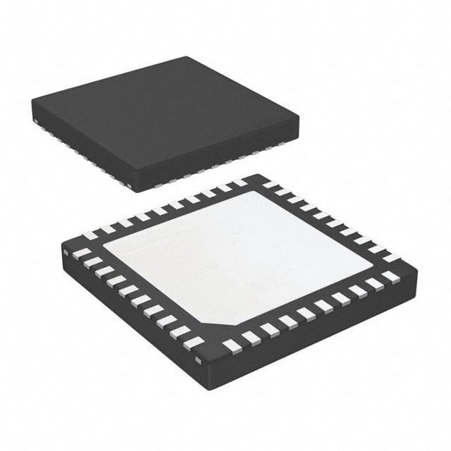
Texas Instruments LMH1983SQ/NOPB
- Part No.:
- LMH1983SQ/NOPB
- Manufacturer:
- Texas Instruments
- Category:
- Video Processing
- Package:
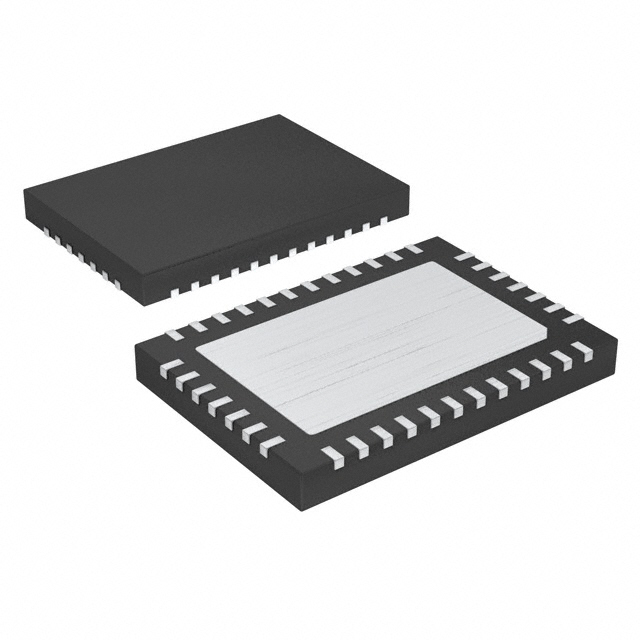
- 40-WFQFN Exposed Pad
- Datasheet:
-
 LMH1983SQ/NOPB.pdf
- Description:
- IC VIDEO CLOCK GENERATOR 40WQFN
- Quantity:
- Payment:

- Shipping:

Inventory:815
Please send an inquiry. Send us your inquiry, and we will respond immediately.
Product details
Overview
LMH1983SQ/NOPB from Texas Instruments is a programmable 3G/HD/SD video clock generator IC with four integrated PLLs, delivering genlocked 27 MHz, 148.5 MHz, 148.35 MHz, and 24.576 MHz clocks for SDI SerDes, FPGA reference cleaning, and audio embed/de-embed applications in broadcast equipment. It supports automatic input format detection (525i/1080p), digital holdover on loss of reference, and LVDS/LVCMOS outputs.
For engineers reviewing the LMH1983SQ/NOPB datasheet, LMH1983SQ/NOPB pinout, LMH1983SQ/NOPB application, or LMH1983SQ/NOPB equivalent, this page provides verified technical context, jitter performance data (≤4 ps deterministic jitter at 148.35 MHz), dual-stage PLL architecture details, frame-synchronized TOF pulse generation, and real-world selection guidance against comparable A/V clock generators.
Technical Context
The LMH1983SQ/NOPB implements a two-stage PLL architecture: PLL1 uses an external 27 MHz VCXO and loop filter to generate a low-jitter reference, while PLL2–PLL4 integrate on-chip VCOs to produce synchronized video (148.5/148.35 MHz) and audio (24.576 MHz) clocks. All four PLLs support independent top-of-frame (TOF) timing pulses with programmable alignment.
It features automatic HVF sync detection, I²C programmability (3 address options), 3×2 video clock crosspoint routing, and configurable loss-of-reference behavior-enabling digital holdover (±0.5 ppm typical accuracy) or free-run mode via VC_LPF analog control. Output jitter is specified at ≤4 ps (TIE deterministic) for CLKout3 at 148.35 MHz under default conditions.
Key Specifications
| Parameter | Value and Actual Design Meaning |
|---|---|
| Output Clocks | Four independent LVDS outputs: CLKout1 (27 MHz), CLKout2 (148.5 MHz), CLKout3 (148.35 MHz), CLKout4 (24.576 MHz) |
| Deterministic Jitter | ≤4 ps TIE at CLKout3 (148.35 MHz); ≤8 ps at CLKout2 (148.5 MHz); ≤15 ps at CLKout4 (24.576 MHz) |
| Random Jitter | 3.5 ps TIE (CLKout3), 3.0 ps (CLKout2), 2.7 ps (CLKout1), 3.4 ps (CLKout4) |
| Frame Timing Outputs | Fout1–Fout4 provide programmable top-of-frame (TOF) pulses synchronized to respective clock outputs |
| Supply Voltage | 3.3 V ±5% single supply; total IDD = 170–212 mA (all PLLs active) |
| Operating Temperature | -40°C to +85°C ambient; junction limit 150°C |
| I²C Interface | 7-bit slave address selectable via ADDR pin (0x65/0x66/0x67); SDA/SCL require 4.7 kΩ pull-ups |
Pinout & Package
LMH1983SQ/NOPB is housed in a 40-pin WQFN package (6.00 mm × 6.00 mm) with exposed thermal pad (DAP) requiring PCB ground connection. Power distribution includes eight VDD pins (3.3 V for PLL1, logic, CLKout drivers, and LDO bias rails), four GND pins, and dedicated bypass capacitor terminals (Cbyp2/Cbyp3/Cbyp4).
| Pin/Terminal | Circuit Role | Design Meaning |
|---|---|---|
| 1–2, 10, 16, 19–20, 31–32, 38 | VDD | Separate 3.3 V supply domains for PLL1, logic I/O, CLKout1–4 drivers, and internal LDOs-enabling noise isolation and rail-specific decoupling |
| 3–5, 7, 9, 11–13, 17, 22, 28, 30, 36–37 | Hin/Vin/Fin/ADDR/SDA/SCL/NO_LOCK/NO_ALIGN/NO_REF/Fout4/Fout3/Fout2/Fout1 | LVCMOS inputs/outputs for sync detection, I²C control, status flags, and frame timing-supporting auto-polarity correction and programmable TOF alignment |
| 14–15, 23–24, 28–29, 35–36 | CLKout4±/CLKout3±/CLKout2±/CLKout1± | Differential LVDS clock outputs with adjustable swing (247–454 mV) and common-mode voltage (1.125–1.375 V) via I²C register 0x3A |
| 33–34 | XOin−/XOin+ | Dual-mode VCXO input: accepts 27 MHz LVCMOS (bias XOin− to VDD/2) or LVDS (direct differential drive)-required for register access and PLL1 reference |
| 40 | VC_LPF | Analog output controlling external VCXO frequency; used for holdover (DAC holds voltage) or free-run (external bias sets frequency) |
Key Features
| Feature | Design Value |
|---|---|
| Four independent PLLs with TOF generation | Each of four outputs (CLKout1–4) has a dedicated top-of-frame pulse (Fout1–4) with programmable timing relative to its clock edge-enabling frame-accurate genlock across mixed A/V standards |
| Dual-stage PLL architecture | PLL1 (external VCXO + loop filter) cleans input jitter before feeding PLL2–PLL4 (integrated VCOs), achieving ≤4 ps deterministic jitter at 148.35 MHz without external clock cleaners |
| Digital holdover on loss of reference | Maintains output frequency within ±0.5 ppm of prior locked value by holding VC_LPF voltage-critical for seamless failover in broadcast infrastructure during reference interruption |
| 3×2 video clock crosspoint | Routes any of three video PLL outputs (PLL1/2/3) to any of two video clock outputs (CLKout2/CLKout3), enabling flexible clock assignment for multi-standard SDI transmitters (e.g., 1080p/59.94 and 525i/29.97 simultaneously) |
| Auto-format detection & soft resync | Recognizes 525i, 1080p, and other HVF sync patterns without host intervention; allows glitchless re-synchronization to new reference sources during live switching |
Applications
| Triple-Rate SDI Transmitters | FPGA Reference Clock Cleaning |
|---|---|
|
Use Scenario: Generating compliant 3G-SDI (1080p/59.94), HD-SDI (1080i/59.94), and SD-SDI (525i/29.97) serial digital video clocks with embedded audio timing. IC Role / Device Role / Timing Role: Primary clock generator providing genlocked 148.5 MHz (3G), 148.35 MHz (HD), and 27 MHz (SD) clocks plus frame-synced TOF pulses for serializer timing and audio word clock alignment. Use Value: Eliminates need for discrete VCXOs and multiple PLL ICs; meets SMPTE ST 292/424 jitter specs (<0.2 UI peak-to-peak) using internal low-jitter architecture. |
Use Scenario: Supplying ultra-low-jitter reference clocks to Xilinx or Intel FPGAs used in video processing pipelines, where phase noise directly impacts ADC/DAC sampling integrity. IC Role / Device Role / Timing Role: High-stability clock source delivering 148.5 MHz or 148.35 MHz LVDS clocks with ≤4 ps deterministic jitter to FPGA transceiver banks and logic fabric. Use Value: Reduces bit-error rates in high-speed SerDes links and improves signal-to-noise ratio in video digitization by minimizing clock-induced sampling uncertainty. |
| Audio Embed/De-embed Systems | Frame Synchronizers (Genlock/DARS) |
|
Use Scenario: Providing synchronized 24.576 MHz audio word clock and 148.35 MHz video clock to AES3 embedders/de-embedders operating on 1080p/59.94 SDI streams. IC Role / Device Role / Timing Role: Dual-domain timing engine generating audio clock (PLL4) and video clock (PLL3) with precise phase relationship-ensuring zero-audio-frame-skew during embedding. Use Value: Enables sample-accurate audio/video alignment without external delay calibration; supports dynamic format switching (e.g., 1080p ↔ 720p) with soft resync. |
Use Scenario: Genlocking multiple video sources (cameras, playback servers) to a common house reference in live production switchers or distributed antenna relay systems (DARS). IC Role / Device Role / Timing Role: Reference-tracking clock generator producing stable local clocks aligned to incoming H/V/F sync, with holdover capability during reference loss. Use Value: Maintains frame coherence across all downstream devices for >1 second after reference failure-preventing visible frame slips or audio dropouts during switchover. |
Equivalent & Alternatives
The following parts are listed as comparable options for similar video clock generation applications.
| Alternative Part | Technical Difference | Application Difference | Selection Advice |
|---|---|---|---|
| LMH1981MTX/NOPB | Single PLL architecture; no PLL2–PLL4; outputs only 27 MHz and derived TOF; no audio clock generation | Limited to SD/HD baseband sync separation-not suitable for 3G-SDI or multi-clock A/V systems | Select when only HVF sync extraction and basic 27 MHz genlock are required; lower cost but no multi-rate flexibility |
| Si5338A-A-GM | Four-output programmable clock generator with fractional-N synthesis; no dedicated TOF outputs; jitter performance varies by configuration (typ. 0.6 ps RMS) | Broad applicability beyond broadcast (datacom, test equipment); requires complex register setup for video timing | Choose for non-broadcast designs needing arbitrary frequencies or tighter RMS jitter; avoid when TOF pulse synchronization or SMPTE compliance is mandatory |
Compared with LMH1983SQ/NOPB, LMH1981MTX/NOPB lacks multi-PLL video clock synthesis and audio clock capability, while Si5338A-A-GM offers superior RMS jitter but requires extensive configuration to replicate frame-locked TOF behavior and does not natively support SMPTE video standard timing modes.
Availability
LMH1983SQ/NOPB is available at Aetrix Electronics and suitable for broadcast infrastructure, professional video equipment, and FPGA-based media processing systems requiring stable component supply, long-term lifecycle support, and guaranteed traceable sourcing.
Supply support for LMH1983SQ/NOPB includes scheduled delivery planning, volume procurement assistance, BOM continuity management, traceable sourcing, and lifecycle availability coordination for OEM customers, industrial embedded developers, connected-device designers, and electronics production programs.
Manufacturer
Texas Instruments is a global semiconductor leader specializing in analog and embedded processing technologies, with deep expertise in high-performance timing solutions for professional video and communications markets.
The LMH1983SQ/NOPB belongs to TI's broadcast-grade video clock generator product line, designed specifically to replace discrete PLL/VCXO combinations in SMPTE-compliant SDI equipment while simplifying layout and improving jitter performance.
FAQ
What is the primary function of the LMH1983SQ/NOPB in a broadcast video system?
The LMH1983SQ/NOPB serves as a fully integrated video clock generator that produces genlocked 27 MHz, 148.5 MHz, 148.35 MHz, and 24.576 MHz clocks for SDI transmitters, FPGA reference cleaning, and audio embed/de-embed functions. Its four PLLs and dedicated TOF outputs enable frame-accurate synchronization across mixed A/V standards without external clock cleaners-making LMH1983SQ/NOPB essential for SMPTE-compliant broadcast infrastructure.
How does the LMH1983SQ/NOPB achieve low output jitter without external clock cleaning circuits?
The LMH1983SQ/NOPB achieves low jitter through its dual-stage PLL architecture: PLL1 uses an external 27 MHz VCXO and loop filter to generate an ultra-clean reference, which then feeds PLL2–PLL4 with integrated VCOs. This design attenuates input timing jitter at the first stage, enabling deterministic jitter as low as 4 ps at 148.35 MHz-meeting stringent SMPTE ST 292/424 output jitter requirements without additional components. The LMH1983SQ/NOPB thus eliminates the need for external clock cleaners in most broadcast designs.
Can the LMH1983SQ/NOPB operate without an external 27 MHz VCXO?
No-the LMH1983SQ/NOPB requires an external 27 MHz VCXO connected to XOin+ and XOin− pins for PLL1 operation and I²C register access. However, the device supports an alternative OSCin mode on Fout4 pin: when enabled via I²C, a 27 MHz clock applied there can bypass PLL1 and directly feed PLL2–PLL4 for standalone audio/video clock generation. In all cases, the LMH1983SQ/NOPB cannot function without a 27 MHz timing source-either via XOin or OSCin.
What happens to LMH1983SQ/NOPB outputs during loss of reference (LOR)?
Upon loss of reference, the LMH1983SQ/NOPB enters either digital holdover or free-run mode based on configuration. In holdover mode, it maintains output frequency within ±0.5 ppm of the last locked value by holding the VC_LPF control voltage-preserving frame alignment for up to ~1 second. In free-run mode, an external bias on VC_LPF sets the output frequency. Both modes assert the NO_REF flag, and the LMH1983SQ/NOPB supports glitch-less resynchronization when reference returns.
Does the LMH1983SQ/NOPB support automatic detection of video input formats like 525i or 1080p/59.94?
Yes-the LMH1983SQ/NOPB features hardware-based auto-format detection that recognizes major video standards including 525i/29.97, 1080p/59.94, 720p/59.94, and 1080i/59.94 from Hin/Vin/Fin inputs. Detection completes within 2–4 frames, and the device automatically configures PLL dividers and TOF timing accordingly. This eliminates manual register programming for format changes and enables LMH1983SQ/NOPB to adapt dynamically to live video source switching in production environments.
LMH1983SQ/NOPB Specifications
- Product attributes
- Attribute value
- Manufacturer:
- Texas Instruments
- Series:
- -
- Package/Case:
- 40-WFQFN Exposed Pad
- Packaging:
- Tape & Reel (TR)
- Product Status:
- Active
- Function:
- Generator
- Applications:
- Professional Video
- Standards:
- NTSC, PAL
- Control Interface:
- I2C
- Voltage - Supply:
- 3.3V ~ 3.6V
- Mounting Type:
- Surface Mount
- Grade:
- -
- Qualification:
- -
- Supplier Device Package:
- 40-WQFN (6x6)
LMH1983SQ/NOPB FAQ
1.How can I place an order for LMH1983SQ/NOPB through Aetrix?
Please submit a Request for Quotation (RFQ) for LMH1983SQ/NOPB on Aetrix. Our sales agent will provide a competitive quotation and guide you through the order confirmation once you accept the terms.
2.Are the price and stock information for LMH1983SQ/NOPB reliable?
The price and inventory of LMH1983SQ/NOPB are updated periodically and may fluctuate due to market conditions. Stock and pricing data are typically refreshed every 24 hours. Quotation validity for LMH1983SQ/NOPB is usually 5 days.
3.What payment methods are accepted for LMH1983SQ/NOPB?
We accept Wire Transfer, PayPal, Credit Card, Western Union, MoneyGram, and Escrow for LMH1983SQ/NOPB transactions.
Note: Certain payment methods may incur a processing fee.
4.How is shipping managed for LMH1983SQ/NOPB?
LMH1983SQ/NOPB orders can be shipped via leading logistics carriers, including DHL, UPS, FedEx, TNT, or Registered Mail.
Once your LMH1983SQ/NOPB order is processed, you will receive an email with the shipment details and tracking number.
Note: Tracking information may take up to 24 hours to appear. Express delivery typically takes 3–5 business days.
5.How can I obtain technical support or documentation for LMH1983SQ/NOPB?
For technical support, including LMH1983SQ/NOPB datasheets, pinout diagrams, or application guidance, please contact our engineering support team. They can provide detailed documentation and assistance for your LMH1983SQ/NOPB requirements.
6.How does Aetrix verify that LMH1983SQ/NOPB is sourced from the original manufacturer or authorized distributors?
All LMH1983SQ/NOPB products on Aetrix are procured from qualified distributors and authorized channels. Our dedicated quality assurance team conducts strict verification, including traceability checks and, if necessary, third-party testing. This ensures that LMH1983SQ/NOPB meets industry standards.
7.What is the process for return or replacement of LMH1983SQ/NOPB?
All LMH1983SQ/NOPB units undergo pre-shipment inspection (PSI). If there is an issue with LMH1983SQ/NOPB, returns or replacements are accepted under the following conditions:
1.Quantity discrepancies, incorrect items, or visible external defects (such as breakage or corrosion), acknowledged by Aetrix.
2.The issue is reported within 90 days of delivery.
3.The LMH1983SQ/NOPB part is unused and in its original packaging.
Return procedure for LMH1983SQ/NOPB:
1.Submit a request within 90 days.
2.Obtain a Return Material Authorization (RMA) from Aetrix.
LMH1983SQ/NOPB Tags
-
HDMI2C1-6C1
STMicroelectronics
-
ADA4430-1YKSZ-R7
Analog Devices Inc.

-
LM1881MX/NOPB
Texas Instruments

-
SN75DP130SSRGZR
Texas Instruments
-
EQCO30T5.2
Microchip Technology

-
LMH1980MM/NOPB
Texas Instruments
-
EQCO30R5.D
Microchip Technology

-
SII9022ACNU
Lattice Semiconductor Corporation
-
SN65DP159RGZR
Texas Instruments

-
SN65DP159RSBR
Texas Instruments
-
SN65DP141RLJR
Texas Instruments
-
LMH0303SQ/NOPB
Texas Instruments
Tech Hub

A practical engineering guide to 3.3V and 5V logic compatibility, input thresholds, resistor dividers, translator ICs, MOSFET level shifting, I2C pull-ups, timing limits and power-sequencing risks.

The 74HC595 uses push-pull logic outputs, while the TPIC6B595 uses 50 V open-drain DMOS sinks for higher-power loads. This guide compares timing, current limits, 3.3 V interfacing, load wiring, thermal…

The 74HC595 converts serial data into eight stable parallel outputs. This guide covers pin functions, shift and storage timing, OE and MR behavior, drive-current limits, cascading, voltage compatibilit…

A technical comparison of level-sensitive latches and edge-triggered flip-flops, covering timing windows, setup and hold limits, master–slave operation, time borrowing, race-through, HDL inference and…

A D latch stores one bit while Enable controls when data can pass. This reference covers gate-level operation, truth tables, transparency, setup and hold timing, LE versus OE, common ICs and practical …

An SR latch stores one bit through cross-coupled feedback. This engineering reference covers NOR and NAND implementations, truth tables, forbidden-state recovery, gated operation, switch debouncing, fa…

Latch circuits retain one bit through feedback. This technical reference covers SR and D latches, truth tables, transparency, timing limits, latch-versus-flip-flop behavior, applications and common log…

An engineering guide to LED driver operation, constant-current and constant-voltage outputs, linear and switching topologies, dimming, IC selection, calculations, replacement compatibility, and fault c…

Operational amplifier guide covering op amp basics, feedback, ideal vs real op amps, common configurations, buffer circuits, offset, bias current, gain-bandwidth, slew rate, rail-to-rail limits and sel…

Jumper cables guide covering safe connection order, red and black clamp placement, final ground connection, cable gauge, length, clamp quality, copper vs CCA cables, jump starter comparison and battery…


