
 My Inquiry
 My Account


Texas Instruments LMH1983SQX/NOPB
- Part No.:
- LMH1983SQX/NOPB
- Manufacturer:
- Texas Instruments
- Category:
- Video Processing
- Package:
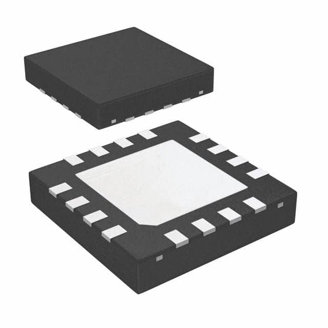
- 40-WFQFN Exposed Pad
- Datasheet:
-
 LMH1983SQX/NOPB.pdf
- Description:
- IC VIDEO CLOCK GENERATOR 40WQFN
- Quantity:
- Payment:

- Shipping:

Inventory:4,192
Please send an inquiry. Send us your inquiry, and we will respond immediately.
Product details
Overview
LMH1983SQX/NOPB from Texas Instruments is a programmable 3G/HD/SD video clock generator IC with four integrated PLLs, generating synchronized 27 MHz, 148.5 MHz, 148.35 MHz, and 24.576 MHz clocks for SDI SerDes, FPGA reference, and audio embed/de-embed applications. It supports genlock to HVF sync inputs and delivers sub-4 ps deterministic jitter on HD video outputs.
For engineers reviewing the LMH1983SQX/NOPB datasheet, LMH1983SQX/NOPB pinout, LMH1983SQX/NOPB application, or LMH1983SQX/NOPB equivalent, key selection criteria include dual-stage PLL architecture (VCXO-based PLL1 + VCO-based PLL2–PLL4), 40-pin WQFN package with exposed thermal pad, LVDS clock outputs, I²C programmability, and digital holdover capability during loss of reference.
Technical Context
The LMH1983SQX/NOPB implements a two-stage analog PLL architecture: PLL1 uses an external 27 MHz VCXO and loop filter (via VC_LPF) for ultra-low-jitter reference generation, while PLL2–PLL4 are on-chip VCO-based PLLs deriving from PLL1's clean output. PLL2 and PLL3 provide fixed-ratio multiplication to 148.5 MHz and 148.35 MHz for SMPTE-compliant HD-SDI; PLL4 generates 24.576 MHz (or 98.304 MHz / 2X) for AES3 audio timing.
It features three independent 2×2 video clock crosspoints, four programmable frame timing outputs (Fout1–Fout4), automatic input format detection (525i/1080p/29.97/59.94 Hz), and real-time status flags (NO_REF, NO_LOCK, NO_ALIGN). All four clock outputs support LVDS differential signaling with <4 ps deterministic jitter at 148.35 MHz and <15 ps at 24.576 MHz.
Key Specifications
| Parameter | Value and Actual Design Meaning |
|---|---|
| Output Clocks | Four independent LVDS outputs: CLKout1 (27 MHz), CLKout2 (148.5 MHz), CLKout3 (148.35 MHz), CLKout4 (24.576 MHz default) |
| Deterministic Jitter | 4 ps (CLKout3 @ 148.35 MHz), 8 ps (CLKout2 @ 148.5 MHz), 15 ps (CLKout4 @ 24.576 MHz) - meets SMPTE ST 259/424 jitter compliance without external cleaning |
| PLL Architecture | Dual-stage: PLL1 (external 27 MHz VCXO + analog loop filter), PLL2–PLL4 (integrated VCOs with programmable dividers) |
| Frame Timing Outputs | Fout1–Fout4: Four LVCMOS TOF (Top-of-Frame) pulses, each assignable to PLL1/2/3/4, with ≤22 ns delay alignment |
| Supply & Interface | 3.3 V single supply; I²C interface (3 address options: 0x65/0x66/0x67); 40-pin WQFN (6.0 × 6.0 mm, 0.5 mm pitch, exposed DAP) |
| Holdover Accuracy | ±0.5 ppm typical frequency retention during loss of reference, enabled via internal 10-bit DAC controlling VCXO bias |
| Input Reference Support | Hin/Vin/Fin (LVCMOS), 27 MHz XOin (LVCMOS/LVDS), OSCin (27 MHz external clock for PLL4 bypass mode) |
Pinout & Package
LMH1983SQX/NOPB is housed in a 40-pin WQFN package (6.0 mm × 6.0 mm, 0.5 mm pitch) with exposed die attach pad (DAP) requiring PCB grounding for thermal and electrical integrity.
| Pin/Terminal | Circuit Role | Design Meaning |
|---|---|---|
| 1,2,10,16,19,20,21,31,32,38,39 | VDD | Dedicated 3.3 V power domains per PLL stage and I/O bank - decoupling required per pin (Cbyp2/Cbyp3/Cbyp4 specified) |
| 3,4,5 | Hin, Vin, Fin | LVCMOS video sync inputs for auto-format detection (525i, 1080p, 29.97/59.94 Hz); polarity-corrected internally |
| 14,15,23,24,28,29,35,36 | CLKout4±, CLKout3±, CLKout2±, CLKout1± | Differential LVDS clock outputs - each pair supports independent frequency selection and shutdown (Hi-Z) |
| 17,22,30,37 | Fout4, Fout3, Fout2, Fout1 | LVCMOS frame timing outputs - programmable TOF pulse assignment to PLL1–PLL4; active-low, format-synced |
| 11,12,13 | NO_LOCK, NO_ALIGN, NO_REF | Open-drain status flags - indicate PLL lock loss, output misalignment, or reference loss; maskable per PLL/output |
| 33,34 | XOin−, XOin+ | Differential or single-ended 27 MHz VCXO input - requires external loop filter on VC_LPF (Pin 40) for PLL1 control |
| 40 | VC_LPF | Analog output - carries charge-pump voltage for VCXO tuning; used for holdover (DAC) or free-run (bias) modes |
Key Features
| Feature | Design Value |
|---|---|
| Four independent PLLs with dedicated VCOs | Enables simultaneous genlocked generation of SD/HD/3G-SDI clocks (27/148.5/148.35 MHz) and AES3 audio clock (24.576 MHz) without external components |
| Programmable video clock crosspoint (3×2) | Routes any of three PLL outputs (PLL1/2/3) to any of two clock outputs (CLKout1–CLKout3), enabling flexible format switching in broadcast gear |
| Digital holdover with ±0.5 ppm accuracy | Maintains stable output frequency during brief reference loss using internal 10-bit DAC to hold VCXO control voltage - critical for frame-synchronous broadcast switching |
| Soft resynchronization | Glitch-free re-lock to new reference without disrupting downstream SerDes or FPGA logic - achieved via phase-aligned TOF pulse regeneration |
| I²C interface with 3-address select | Supports up to three devices on same bus (0x65/0x66/0x67); enables configuration of all PLL dividers, output formats, TOF timing, and status masks |
Applications
| Triple-Rate SDI Transmitter | FPGA Reference Clock Generation |
|---|---|
|
Use Scenario: Generating compliant 3G-SDI (1080p60), HD-SDI (1080i59.94), and SD-SDI (525i29.97) clocks with embedded audio timing in professional video infrastructure. IC Role / Device Role / Timing Role: Primary clock generator providing genlocked LVDS clocks (CLKout2/CLKout3) and frame-sync TOF pulses (Fout2/Fout3) to SDI encoder ASICs. Use Value: Eliminates need for discrete VCXOs and multiple PLL ICs; sub-4 ps jitter ensures SMPTE ST 424 eye diagram compliance without external jitter cleaners. |
Use Scenario: Supplying low-jitter, multi-frequency reference clocks to Xilinx or Intel FPGAs used in video processing pipelines with dynamic format switching. IC Role / Device Role / Timing Role: Centralized clock source delivering 27 MHz (configuration), 148.5 MHz (pixel clock), and 24.576 MHz (audio sample clock) simultaneously to FPGA banks. Use Value: Reduces board space and power vs. discrete oscillators; I²C programmability allows runtime clock reconfiguration during format transitions (e.g., 1080p → 4K). |
| Audio Embed/De-embed System | Frame Synchronizer (Genlock/DARS) |
|
Use Scenario: Providing precisely timed audio word clocks and video frame markers to AES3 embedders/de-embedders in broadcast routers and converters. IC Role / Device Role / Timing Role: Generates 24.576 MHz audio clock (CLKout4) and synchronized AVF pulse (Fout4) aligned to video frame boundaries. Use Value: Ensures zero-audio-frame-skew between embedded audio and video; TOF4 programmability supports AES3 channel alignment across multiple devices. |
Use Scenario: Maintaining precise phase alignment between incoming asynchronous video signals and local master timing in digital audio routing switches (DARS) or master control rooms. IC Role / Device Role / Timing Role: Genlocking all outputs to external HVF reference while retaining short-term stability during reference interruption via digital holdover. Use Value: ±0.5 ppm holdover accuracy prevents visible frame tearing during reference switchover; NO_REF/NO_LOCK flags enable automated failover logic. |
Equivalent & Alternatives
The following parts are listed as comparable options for similar video clock generation applications.
| Alternative Part | Technical Difference | Application Difference | Selection Advice |
|---|---|---|---|
| LMH1982SQX/NOPB | Three-PLL variant (no PLL4); lacks audio clock generation and Fout4; identical video clock specs and pinout | Not suitable for AES3 audio embed/de-embed; limited to video-only timing in SD/HD/3G systems | Select when audio clock functionality is unnecessary and BOM cost reduction is prioritized over feature flexibility |
| Si5338A-D-GM | Four-output clock generator with fractional-N synthesizers; no native HVF sync detection; higher integration (on-chip LDOs, EEPROM) | Requires external MCU for format detection logic; better suited for non-broadcast, multi-protocol timing (PCIe, USB, Ethernet) | Choose for mixed-signal systems needing programmable jitter filtering and multi-protocol support, not SMPTE-genlock-critical broadcast gear |
Compared with LMH1983SQX/NOPB, LMH1982SQX/NOPB reduces system complexity where audio clocking is handled externally, while Si5338A-D-GM offers broader protocol coverage but requires firmware-based sync interpretation - making LMH1983SQX/NOPB uniquely optimized for SMPTE-compliant, hardware-genlocked video infrastructure.
Availability
LMH1983SQX/NOPB is available at Aetrix Electronics and suitable for triple-rate SDI transmitter design, FPGA reference clock cleaning, and broadcast-grade audio embed/de-embed systems requiring stable component supply across long production lifecycles.
Supply support for LMH1983SQX/NOPB includes scheduled delivery planning, volume procurement assistance, BOM continuity management, traceable sourcing, and lifecycle availability coordination for OEM customers, industrial embedded developers, connected-device designers, and electronics production programs.
Manufacturer
Texas Instruments is a global semiconductor leader specializing in analog, embedded processing, and high-reliability signal chain solutions for industrial, automotive, and communications markets.
The LMH1983SQX/NOPB belongs to TI's broadcast video timing product line, engineered specifically for SMPTE-compliant genlock, frame synchronization, and multi-standard A/V clock generation in professional video equipment.
FAQ
What is the primary function of the LMH1983SQX/NOPB in broadcast video systems?
The LMH1983SQX/NOPB serves as a fully integrated video clock generator that produces genlocked 27 MHz, 148.5 MHz, 148.35 MHz, and 24.576 MHz clocks for SDI SerDes, FPGA reference, and AES3 audio timing. Its four PLLs, automatic HVF format detection, and TOF pulse generation make LMH1983SQX/NOPB essential for maintaining frame-accurate synchronization across professional broadcast infrastructure without external jitter cleaners.
How does the LMH1983SQX/NOPB achieve low jitter performance on its HD-SDI outputs?
The LMH1983SQX/NOPB achieves sub-4 ps deterministic jitter on CLKout3 (148.35 MHz) by using a dual-stage PLL architecture: PLL1 locks an external low-noise 27 MHz VCXO to the video reference, providing an ultra-clean base clock; PLL2 and PLL3 then multiply this stable reference with high-bandwidth VCOs. This architecture isolates input jitter and minimizes transfer, ensuring LMH1983SQX/NOPB meets SMPTE ST 424 jitter requirements without additional circuitry.
Can the LMH1983SQX/NOPB operate without an external VCXO?
No - the LMH1983SQX/NOPB requires an external 27 MHz VCXO connected to XOin+ and XOin− (Pins 33–34) for PLL1 operation. However, it supports an alternative "OSCin" mode on Pin 17 (Fout4) where a 27 MHz clock can be applied to bypass PLL1 and directly drive PLL4 for standalone audio clock generation - but video clock genlock functionality remains disabled without the VCXO.
What happens to the LMH1983SQX/NOPB outputs during loss of reference (LOR)?
During loss of reference, the LMH1983SQX/NOPB enters either digital holdover or free-run mode. In holdover, its internal 10-bit DAC holds the VCXO control voltage (via VC_LPF), maintaining output frequency within ±0.5 ppm of the last locked value. In free-run, an external bias sets the VCXO frequency. Both modes assert the NO_REF flag, and LMH1983SQX/NOPB continues outputting stable clocks without interruption - critical for broadcast continuity.
Is the LMH1983SQX/NOPB pin-compatible with other TI video clock generators?
Yes - the LMH1983SQX/NOPB shares the same 40-pin WQFN package, pinout, and power sequencing as the LMH1982SQX/NOPB. The two devices are hardware-compatible; LMH1983SQX/NOPB adds PLL4 and Fout4 functionality while retaining identical footprint, register map structure, and I²C interface behavior - enabling drop-in upgrade paths in existing designs requiring audio clock support.
LMH1983SQX/NOPB Specifications
- Product attributes
- Attribute value
- Manufacturer:
- Texas Instruments
- Series:
- -
- Package/Case:
- 40-WFQFN Exposed Pad
- Packaging:
- Tape & Reel (TR)
- Product Status:
- Active
- Function:
- Generator
- Applications:
- Professional Video
- Standards:
- NTSC, PAL
- Control Interface:
- I2C
- Voltage - Supply:
- 3.3V ~ 3.6V
- Mounting Type:
- Surface Mount
- Grade:
- -
- Qualification:
- -
- Supplier Device Package:
- 40-WQFN (6x6)
LMH1983SQX/NOPB FAQ
1.How can I place an order for LMH1983SQX/NOPB through Aetrix?
Please submit a Request for Quotation (RFQ) for LMH1983SQX/NOPB on Aetrix. Our sales agent will provide a competitive quotation and guide you through the order confirmation once you accept the terms.
2.Are the price and stock information for LMH1983SQX/NOPB reliable?
The price and inventory of LMH1983SQX/NOPB are updated periodically and may fluctuate due to market conditions. Stock and pricing data are typically refreshed every 24 hours. Quotation validity for LMH1983SQX/NOPB is usually 5 days.
3.What payment methods are accepted for LMH1983SQX/NOPB?
We accept Wire Transfer, PayPal, Credit Card, Western Union, MoneyGram, and Escrow for LMH1983SQX/NOPB transactions.
Note: Certain payment methods may incur a processing fee.
4.How is shipping managed for LMH1983SQX/NOPB?
LMH1983SQX/NOPB orders can be shipped via leading logistics carriers, including DHL, UPS, FedEx, TNT, or Registered Mail.
Once your LMH1983SQX/NOPB order is processed, you will receive an email with the shipment details and tracking number.
Note: Tracking information may take up to 24 hours to appear. Express delivery typically takes 3–5 business days.
5.How can I obtain technical support or documentation for LMH1983SQX/NOPB?
For technical support, including LMH1983SQX/NOPB datasheets, pinout diagrams, or application guidance, please contact our engineering support team. They can provide detailed documentation and assistance for your LMH1983SQX/NOPB requirements.
6.How does Aetrix verify that LMH1983SQX/NOPB is sourced from the original manufacturer or authorized distributors?
All LMH1983SQX/NOPB products on Aetrix are procured from qualified distributors and authorized channels. Our dedicated quality assurance team conducts strict verification, including traceability checks and, if necessary, third-party testing. This ensures that LMH1983SQX/NOPB meets industry standards.
7.What is the process for return or replacement of LMH1983SQX/NOPB?
All LMH1983SQX/NOPB units undergo pre-shipment inspection (PSI). If there is an issue with LMH1983SQX/NOPB, returns or replacements are accepted under the following conditions:
1.Quantity discrepancies, incorrect items, or visible external defects (such as breakage or corrosion), acknowledged by Aetrix.
2.The issue is reported within 90 days of delivery.
3.The LMH1983SQX/NOPB part is unused and in its original packaging.
Return procedure for LMH1983SQX/NOPB:
1.Submit a request within 90 days.
2.Obtain a Return Material Authorization (RMA) from Aetrix.
LMH1983SQX/NOPB Tags
-
HDMI2C1-6C1
STMicroelectronics
-
ADA4430-1YKSZ-R7
Analog Devices Inc.

-
LM1881MX/NOPB
Texas Instruments

-
SN75DP130SSRGZR
Texas Instruments
-
EQCO30T5.2
Microchip Technology

-
LMH1980MM/NOPB
Texas Instruments
-
EQCO30R5.D
Microchip Technology

-
SII9022ACNU
Lattice Semiconductor Corporation
-
SN65DP159RGZR
Texas Instruments

-
SN65DP159RSBR
Texas Instruments
-
SN65DP141RLJR
Texas Instruments
-
LMH0303SQ/NOPB
Texas Instruments
Tech Hub

A practical engineering guide to 3.3V and 5V logic compatibility, input thresholds, resistor dividers, translator ICs, MOSFET level shifting, I2C pull-ups, timing limits and power-sequencing risks.

The 74HC595 uses push-pull logic outputs, while the TPIC6B595 uses 50 V open-drain DMOS sinks for higher-power loads. This guide compares timing, current limits, 3.3 V interfacing, load wiring, thermal…

The 74HC595 converts serial data into eight stable parallel outputs. This guide covers pin functions, shift and storage timing, OE and MR behavior, drive-current limits, cascading, voltage compatibilit…

A technical comparison of level-sensitive latches and edge-triggered flip-flops, covering timing windows, setup and hold limits, master–slave operation, time borrowing, race-through, HDL inference and…

A D latch stores one bit while Enable controls when data can pass. This reference covers gate-level operation, truth tables, transparency, setup and hold timing, LE versus OE, common ICs and practical …

An SR latch stores one bit through cross-coupled feedback. This engineering reference covers NOR and NAND implementations, truth tables, forbidden-state recovery, gated operation, switch debouncing, fa…

Latch circuits retain one bit through feedback. This technical reference covers SR and D latches, truth tables, transparency, timing limits, latch-versus-flip-flop behavior, applications and common log…

An engineering guide to LED driver operation, constant-current and constant-voltage outputs, linear and switching topologies, dimming, IC selection, calculations, replacement compatibility, and fault c…

Operational amplifier guide covering op amp basics, feedback, ideal vs real op amps, common configurations, buffer circuits, offset, bias current, gain-bandwidth, slew rate, rail-to-rail limits and sel…

Jumper cables guide covering safe connection order, red and black clamp placement, final ground connection, cable gauge, length, clamp quality, copper vs CCA cables, jump starter comparison and battery…


