
 My Inquiry
 My Account


Texas Instruments LMK61A2-312M50SIAR
- Part No.:
- LMK61A2-312M50SIAR
- Manufacturer:
- Texas Instruments
- Category:
- Oscillators
- Package:
- 6-SMD Module
- Datasheet:
-
 LMK61A2-312M50SIAR.pdf
- Description:
- SILICONE OSC XO 312.5000MHZ LVDS
- Quantity:
- Payment:

- Shipping:

Inventory:4,543
Please send an inquiry. Send us your inquiry, and we will respond immediately.
Product details
Overview
LMK61A2-312M50SIAR from Texas Instruments is an ultra-low jitter LVDS oscillator generating a precise 312.5 MHz reference clock in a 7 mm × 5 mm 6-pin QFM package. It delivers ±50 ppm total frequency stability, 90 fs RMS jitter (typical at >100 MHz), and –70 dBc PSRR across 50 kHz–1 MHz supply ripple - enabling high-speed SerDes timing in 10G/25G Ethernet line cards and FPGA-based baseband units.
For engineers reviewing the LMK61A2-312M50SIAR datasheet, LMK61A2-312M50SIAR pinout, LMK61A2-312M50SIAR application, or LMK61A2-312M50SIAR equivalent, key selection criteria include differential LVDS output compliance (300–480 mV swing, 125 Ω impedance), OE-controlled high-impedance disable, industrial temperature operation (–40°C to +85°C), and compatibility with standard 7050 XO footprints.
Technical Context
The LMK61A2-312M50SIAR integrates a high-performance PLL-based oscillator core with factory-programmed 312.5 MHz LVDS output, eliminating external crystal and loop filter components. Its internal power conditioning provides robust immunity to supply noise, reducing system-level decoupling complexity.
It operates from a single 3.3 V ±5% supply and supports output enable/disable via LVCMOS-compatible OE pin with internal pull-up. The device is pre-configured for LVDS mode only - not reprogrammable in-system - and targets applications requiring deterministic low-jitter clocking without configuration overhead.
Key Specifications
| Parameter | Value and Actual Design Meaning |
|---|---|
| Output Frequency | 312.5 MHz - precisely matches IEEE 802.3ba 25GBASE-KR/CR and CPRI Option 7/8 reference requirements. |
| Output Format | LVDS - differential signaling with 125 Ω output impedance, compatible with TI's TSW14J56, Xilinx Kintex Ultrascale+, and Intel Stratix 10 SerDes receivers. |
| RMS Phase Jitter (12 kHz–20 MHz) | 100–200 fs typical - meets OC-192 SONET and 25G Ethernet jitter budgets without additional cleanup. |
| Total Frequency Tolerance | ±50 ppm - includes initial tolerance, temperature drift (–40°C to +85°C), voltage variation, solder reflow shift, and 10-year aging. |
| Supply Voltage | 3.3 V ±5% - aligns with standard FPGA I/O bank and ASIC core supply rails; eliminates need for dedicated LDO. |
| PSRR | –70 dBc at 50 kHz–1 MHz - suppresses switching noise from adjacent DC/DC converters without ferrite beads or extra filtering. |
| Package | 6-pin QFM (7.0 mm × 5.0 mm) - pin-compatible with industry-standard 7050 XO footprint, enabling drop-in replacement of legacy oscillators. |
Pinout & Package
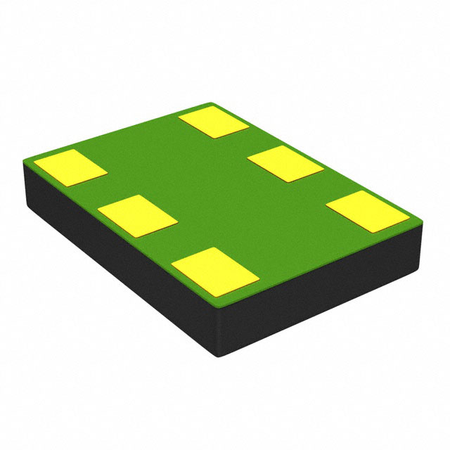
LMK61A2-312M50SIAR uses a 6-pin QFM (SIA) package measuring 7.0 mm × 5.0 mm × 0.9 mm, with exposed thermal pad connected to GND for enhanced thermal dissipation. Pin 1 (OE) is LVCMOS-compatible with internal pull-up; pins 4 and 5 form the LVDS differential pair (OUTP/OUTN); pin 3 is GND; pin 6 is VDD; pin 2 is NC.
| Pin/Terminal | Circuit Role | Design Meaning |
|---|---|---|
| 1 (OE) | Digital control input | Active-low output enable with internal pull-up; drives outputs to high-impedance when low - enables dynamic clock gating in power-sensitive systems. |
| 2 (NC) | No-connect | Unbonded die pad; must remain unconnected on PCB to avoid parasitic coupling or ESD path disruption. |
| 3 (GND) | Analog/digital ground | Common return for all internal circuitry; requires direct connection to solid ground plane via ≥3 thermal vias (0.3 mm diameter). |
| 4 (OUTN) | Differential LVDS output | Inverted leg of 312.5 MHz LVDS signal; routed as matched-length, controlled-impedance pair (100 Ω differential) to receiver. |
| 5 (OUTP) | Differential LVDS output | Non-inverted leg of 312.5 MHz LVDS signal; maintains <10 ps skew vs. OUTN for optimal common-mode rejection. |
| 6 (VDD) | Power supply | 3.3 V analog supply; requires local 10 µF/1 µF/0.1 µF bypass network mounted on component side with shortest possible trace to pin. |
Key Features
| Feature | Design Value |
|---|---|
| Ultra-low jitter (90 fs RMS typical) | Enables clean sampling in 25G+ SerDes PHYs without external jitter cleaners, reducing BOM count and board area. |
| –70 dBc PSRR at 50 kHz–1 MHz | Allows shared 3.3 V rail with noisy digital ICs (e.g., FPGAs, processors), eliminating dedicated low-noise LDOs. |
| ±50 ppm total frequency stability | Meets telecom-grade timing accuracy over full industrial temperature range and 10-year lifetime - no recalibration needed. |
| LVDS output (300–480 mV swing, 125 Ω) | Direct interface to Xilinx UltraScale+ GTY transceivers and Intel Stratix 10 H-tile without external termination resistors. |
| 6-pin 7050-compatible QFM package | Enables mechanical and layout compatibility with existing XO footprints, minimizing PCB redesign effort during upgrade. |
Applications
| 10G/25G Ethernet Line Cards | FPGA-Based Baseband Units (BBUs) |
|---|---|
|
Use Scenario: Providing reference clocks to multiple 25G KR/KR4 SerDes lanes in carrier-grade switch/router line cards. IC Role / Device Role / Timing Role: Primary low-jitter system clock source for PHY layer synchronization and gearbox logic. Use Value: 100–200 fs RMS jitter ensures BER <1e–12 under worst-case channel loss, eliminating need for retiming ICs. |
Use Scenario: Clocking multi-core FPGA fabric and high-speed ADC/DAC interfaces in 5G wireless infrastructure BBUs. IC Role / Device Role / Timing Role: Central timing hub delivering synchronized 312.5 MHz and derived clocks to processing blocks. Use Value: ±50 ppm stability maintains CPRI/ECPRI frame alignment across temperature and aging, avoiding packet slips. |
| Test & Measurement Equipment | Medical Imaging Systems |
|
Use Scenario: Generating stable sampling clocks for high-resolution oscilloscopes and bit-error-rate testers operating above 20 GS/s. IC Role / Device Role / Timing Role: Low-phase-noise clock generator for ADC front-end sampling and digital signal processing clocks. Use Value: –162 dBc/Hz phase noise floor at 10 MHz offset preserves SNR in wideband RF digitization paths. |
Use Scenario: Synchronizing time-of-flight measurements and parallel data acquisition in PET/MRI scanner backends. IC Role / Device Role / Timing Role: Deterministic jitter-free timing reference for high-speed data capture and beamforming engines. Use Value: Industrial temperature rating (–40°C to +85°C) and 125°C junction limit ensure reliability in thermally constrained enclosures. |
Equivalent & Alternatives
The following parts are listed as comparable options for similar ultra-low jitter oscillator applications.
| Alternative Part | Technical Difference | Application Difference | Selection Advice |
|---|---|---|---|
| LMK61E2-312M50SIAR | Same 312.5 MHz output but LVPECL format (1 GHz max), higher current draw (208 mA vs. 196 mA), ±50 ppm tolerance. | Requires 50 Ω AC-coupled termination and negative voltage margin; unsuitable for LVDS-only receivers. | Select only if system uses LVPECL inputs (e.g., older ASICs) and can accommodate higher power and different termination. |
| Si5338A-B-GM | Programmable 4-output clock generator (I²C-configurable), 100 fs RMS jitter, ±10 ppm initial accuracy, 3.3 V supply. | Supports multiple frequencies and formats simultaneously; requires firmware initialization and external EEPROM. | Choose when flexible multi-frequency generation is needed; avoid if single-fixed-frequency simplicity and zero-configuration are priorities. |
Compared with LMK61E2-312M50SIAR and Si5338A-B-GM, the LMK61A2-312M50SIAR offers plug-and-play LVDS timing with lowest design overhead, while maintaining best-in-class jitter and industrial reliability - ideal for volume production where configuration complexity and supply chain variability must be minimized.
Availability
LMK61A2-312M50SIAR is available at Aetrix Electronics and suitable for 10G/25G Ethernet line cards, FPGA-based baseband units, test and measurement equipment, and medical imaging systems requiring stable component supply, long-term lifecycle support, and guaranteed traceability.
Supply support for LMK61A2-312M50SIAR includes scheduled delivery planning, volume procurement assistance, BOM continuity management, traceable sourcing, and lifecycle availability coordination for OEM customers, industrial embedded developers, connected-device designers, and electronics production programs.
Manufacturer
Texas Instruments is a global semiconductor company headquartered in Dallas, Texas, specializing in analog, embedded processing, and high-performance timing solutions for industrial, automotive, and communications markets.
The LMK61XX family was designed to replace quartz-based oscillators in high-speed digital systems, delivering ultra-low jitter, superior PSRR, and factory-programmed flexibility - with the LMK61A2 series optimized specifically for LVDS output in telecom and datacenter infrastructure.
FAQ
What output format does the LMK61A2-312M50SIAR support?
The LMK61A2-312M50SIAR is factory-programmed exclusively for LVDS output. It delivers a 312.5 MHz differential signal with 300–480 mV swing, 125 Ω output impedance, and 45–55% duty cycle. Unlike programmable variants, it does not support LVPECL or HCSL modes - the LMK61A2-312M50SIAR is fixed-function and requires no configuration.
Does the LMK61A2-312M50SIAR require external configuration or programming?
No, the LMK61A2-312M50SIAR is fully factory-programmed and operates immediately upon power-up with no external configuration required. It has no I²C, SPI, or pin-strapping interface. The LMK61A2-312M50SIAR is a turnkey oscillator - simply apply 3.3 V, connect OE high (or leave floating due to internal pull-up), and use the LVDS outputs.
What is the maximum allowable supply voltage ripple for the LMK61A2-312M50SIAR?
The LMK61A2-312M50SIAR maintains –70 dBc PSRR against 50 mVpp sinusoidal ripple from 50 kHz to 1 MHz. This means a 50 mVpp ripple on the 3.3 V rail induces only –70 dBc spurious content in the 312.5 MHz output spectrum. The LMK61A2-312M50SIAR thus tolerates typical DC/DC switching noise without external filtering beyond standard 10 µF/1 µF/0.1 µF bypassing.
Can the LMK61A2-312M50SIAR be used in place of a 7050-package crystal oscillator?
Yes, the LMK61A2-312M50SIAR uses a 7 mm × 5 mm 6-pin QFM package that is mechanically and pinout-compatible with industry-standard 7050 XO footprints. Pin 1 (OE) maps to the enable function (often unused in basic XOs), while pins 4/5 (OUTP/OUTN) replace the single-ended output. The LMK61A2-312M50SIAR drops into existing layouts with minimal routing changes.
What is the startup time and output enable delay for the LMK61A2-312M50SIAR?
The LMK61A2-312M50SIAR has a typical start-up time of 10 ms - defined as the interval from VDD reaching 3.135 V to valid output - and an output enable delay of 50 µs from OE rising to VIH (1.4 V). These values are specified over –40°C to +85°C and ensure deterministic timing behavior in power-sequenced systems using the LMK61A2-312M50SIAR.
LMK61A2-312M50SIAR Specifications
- Product attributes
- Attribute value
- Manufacturer:
- Texas Instruments
- Series:
- LMK61XX
- Package/Case:
- 6-SMD Module
- Packaging:
- Tape & Reel (TR)
- Product Status:
- Active
- Base Resonator:
- Silicon
- Type:
- XO (Standard)
- Frequency:
- 312.5 MHz
- Function:
- Enable/Disable
- Output:
- LVDS
- Voltage - Supply:
- 3.3V
- Frequency Stability:
- ±50ppm
- Absolute Pull Range (APR):
- -
- Operating Temperature:
- -40°C ~ 85°C
- Spread Spectrum Bandwidth:
- -
- Current - Supply (Max):
- 196mA
- Ratings:
- -
- Mounting Type:
- Surface Mount
- Supplier Device Package:
- 6-QFM (7x5)
- Size / Dimension:
- 0.276" L x 0.197" W (7.00mm x 5.00mm)
- Height - Seated (Max):
- 0.045" (1.15mm)
LMK61A2-312M50SIAR FAQ
1.How can I place an order for LMK61A2-312M50SIAR through Aetrix?
Please submit a Request for Quotation (RFQ) for LMK61A2-312M50SIAR on Aetrix. Our sales agent will provide a competitive quotation and guide you through the order confirmation once you accept the terms.
2.Are the price and stock information for LMK61A2-312M50SIAR reliable?
The price and inventory of LMK61A2-312M50SIAR are updated periodically and may fluctuate due to market conditions. Stock and pricing data are typically refreshed every 24 hours. Quotation validity for LMK61A2-312M50SIAR is usually 5 days.
3.What payment methods are accepted for LMK61A2-312M50SIAR?
We accept Wire Transfer, PayPal, Credit Card, Western Union, MoneyGram, and Escrow for LMK61A2-312M50SIAR transactions.
Note: Certain payment methods may incur a processing fee.
4.How is shipping managed for LMK61A2-312M50SIAR?
LMK61A2-312M50SIAR orders can be shipped via leading logistics carriers, including DHL, UPS, FedEx, TNT, or Registered Mail.
Once your LMK61A2-312M50SIAR order is processed, you will receive an email with the shipment details and tracking number.
Note: Tracking information may take up to 24 hours to appear. Express delivery typically takes 3–5 business days.
5.How can I obtain technical support or documentation for LMK61A2-312M50SIAR?
For technical support, including LMK61A2-312M50SIAR datasheets, pinout diagrams, or application guidance, please contact our engineering support team. They can provide detailed documentation and assistance for your LMK61A2-312M50SIAR requirements.
6.How does Aetrix verify that LMK61A2-312M50SIAR is sourced from the original manufacturer or authorized distributors?
All LMK61A2-312M50SIAR products on Aetrix are procured from qualified distributors and authorized channels. Our dedicated quality assurance team conducts strict verification, including traceability checks and, if necessary, third-party testing. This ensures that LMK61A2-312M50SIAR meets industry standards.
7.What is the process for return or replacement of LMK61A2-312M50SIAR?
All LMK61A2-312M50SIAR units undergo pre-shipment inspection (PSI). If there is an issue with LMK61A2-312M50SIAR, returns or replacements are accepted under the following conditions:
1.Quantity discrepancies, incorrect items, or visible external defects (such as breakage or corrosion), acknowledged by Aetrix.
2.The issue is reported within 90 days of delivery.
3.The LMK61A2-312M50SIAR part is unused and in its original packaging.
Return procedure for LMK61A2-312M50SIAR:
1.Submit a request within 90 days.
2.Obtain a Return Material Authorization (RMA) from Aetrix.
LMK61A2-312M50SIAR Tags
-
ECS-2333-160-BN-TR
ECS Inc.
-
ECS-2333-240-BN-TR
ECS Inc.
-
KC2016Z25.0000C1KX00
KYOCERA AVX
-0.035-Thick.jpg)
-
ECS-2033-250-BN
ECS Inc.
-
O 25,0-JO32-B-1V3-1-T1-LF
Jauch Quartz
-
SIT1533AI-H4-DCC-32.768E
SiTime
-
ECS-2333-500-BN-TR
ECS Inc.
-
COM1305-50.000-EXT-T-TR
Raltron Electronics
-
SG-210STF 24.0000ML0
EPSON
-
ECS-3225MV-320-CN-TR
ECS Inc.
-
ECS-2033-240-BN
ECS Inc.
-
ECS-2333-120-BN-TR
ECS Inc.
Tech Hub

A practical engineering guide to 3.3V and 5V logic compatibility, input thresholds, resistor dividers, translator ICs, MOSFET level shifting, I2C pull-ups, timing limits and power-sequencing risks.

The 74HC595 uses push-pull logic outputs, while the TPIC6B595 uses 50 V open-drain DMOS sinks for higher-power loads. This guide compares timing, current limits, 3.3 V interfacing, load wiring, thermal…

The 74HC595 converts serial data into eight stable parallel outputs. This guide covers pin functions, shift and storage timing, OE and MR behavior, drive-current limits, cascading, voltage compatibilit…

A technical comparison of level-sensitive latches and edge-triggered flip-flops, covering timing windows, setup and hold limits, master–slave operation, time borrowing, race-through, HDL inference and…

A D latch stores one bit while Enable controls when data can pass. This reference covers gate-level operation, truth tables, transparency, setup and hold timing, LE versus OE, common ICs and practical …

An SR latch stores one bit through cross-coupled feedback. This engineering reference covers NOR and NAND implementations, truth tables, forbidden-state recovery, gated operation, switch debouncing, fa…

Latch circuits retain one bit through feedback. This technical reference covers SR and D latches, truth tables, transparency, timing limits, latch-versus-flip-flop behavior, applications and common log…

An engineering guide to LED driver operation, constant-current and constant-voltage outputs, linear and switching topologies, dimming, IC selection, calculations, replacement compatibility, and fault c…

Operational amplifier guide covering op amp basics, feedback, ideal vs real op amps, common configurations, buffer circuits, offset, bias current, gain-bandwidth, slew rate, rail-to-rail limits and sel…

Jumper cables guide covering safe connection order, red and black clamp placement, final ground connection, cable gauge, length, clamp quality, copper vs CCA cables, jump starter comparison and battery…


