
 My Inquiry
 My Account


Texas Instruments LP5012RUKR
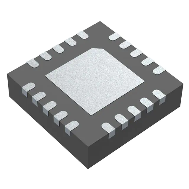
- Part No.:
- LP5012RUKR
- Manufacturer:
- Texas Instruments
- Category:
- LED Drivers
- Package:
- 20-WFQFN Exposed Pad
- Datasheet:
-
 LP5012RUKR.pdf
- Description:
- IC LED DRVR LIN PWM 35MA 20WQFN
- Quantity:
- Payment:

- Shipping:

Inventory:2,805
Please send an inquiry. Send us your inquiry, and we will respond immediately.
Product details
Overview
LP5012RUKR from Texas Instruments is a 12-channel, 12-bit PWM constant-current sink LED driver optimized for RGB lighting control in human-machine interface applications. It operates from 2.7 V to 5.5 V, delivers up to 35 mA per channel at VCC ≥ 3.3 V, features 29-kHz PWM switching to eliminate audible noise, and achieves ±5% device-to-device and channel-to-channel current accuracy. It is used in smart speaker indicator systems requiring smooth breathing/fading effects with minimal MCU overhead.
For engineers reviewing the LP5012RUKR datasheet, LP5012RUKR pinout, LP5012RUKR application, or LP5012RUKR equivalent, this page provides verified technical context on its I²C-controlled RGB bank architecture, ultra-low 10 µA power-save mode, 20-pin WQFN package with exposed thermal pad, and real-world implementation constraints for battery-powered smart home devices.
Technical Context
The LP5012RUKR integrates twelve independent 12-bit PWM generators clocked at 29 kHz, each accepting separate 8-bit color-mixing and 8-bit brightness-control inputs. Its three programmable RGB banks (A/B/C) enable synchronized global effects-e.g., fade-in/fade-out-without per-channel register writes, reducing I²C traffic and MCU load.
It implements hardware-based 3-phase PWM phase-shifting across output groups (OUT0/3/6/9, OUT1/4/7/10, OUT2/5/8/11) to reduce peak input current and ceramic capacitor ringing. Current setting is unified via a single external IREF resistor, with two hardware address pins (ADDR0/ADDR1) supporting up to four devices on one I²C bus at 400-kHz fast-mode speed.
Key Specifications
| Parameter | Value and Actual Design Meaning |
|---|---|
| VCC Range | 2.7 V to 5.5 V - supports direct connection to common system rails without level shifters. |
| Max Output Current | 35 mA per channel at VCC ≥ 3.3 V - enables driving high-brightness RGB LEDs with single-sink topology. |
| PWM Resolution & Frequency | 12-bit resolution at 29 kHz - ensures flicker-free, smooth dimming and eliminates audible coil/LED noise. |
| Quiescent Current | 10 µA typical in power-save mode (all LEDs off >30 ms) - critical for battery-operated smart locks and sensors. |
| I²C Interface | 400-kHz fast-mode compatible - allows rapid configuration of all 12 channels within single I²C transactions using auto-increment. |
| Current Accuracy | ±5% device-to-device and ±5% channel-to-channel - guarantees consistent color balance across multi-LED arrays without per-channel calibration. |
| Output Voltage Headroom | 6 V max - accommodates common 2–3 V forward-voltage RGB LEDs with margin for series resistors or voltage drops. |
Pinout & Package
LP5012RUKR uses a 20-pin WQFN package (RUK) with 3.00 mm × 3.00 mm body and exposed thermal pad (GND). The thermal pad must be soldered to PCB ground for thermal performance and electrical reference.
| Pin/Terminal | Circuit Role | Design Meaning |
|---|---|---|
| OUT0–OUT11 | Constant-current sink outputs | 12 dedicated LED drive terminals; each sinks up to 35 mA; unused pins may float. |
| EN | Chip enable input | Active-high logic control; pulls device into shutdown (1 µA) when low. |
| SCL / SDA | I²C bus interface | Supports 1.8-V/3.3-V/5-V logic levels; SDA is bidirectional with open-drain behavior. |
| ADDR0 / ADDR1 | Hardware slave address selection | Set device I²C address; two pins allow 4 unique addresses (0x60–0x63) on same bus. |
| IREF | Global current reference input | Connects external resistor to set all channel currents simultaneously; 0.7 V reference voltage. |
| VCAP | Internal LDO output filter | Requires 1-µF ceramic capacitor to GND; placement adjacent to pin is mandatory for stability. |
| VCC / GND | Power supply and ground | VCC powers digital and analog blocks; exposed thermal pad serves as primary GND return path. |
Key Features
| Feature | Design Value |
|---|---|
| Independent RGB bank control (A/B/C) | Enables synchronized breathing/fade effects across grouped LEDs using only 4 registers-reducing I²C writes by >75% vs per-channel updates. |
| Logarithmic or linear brightness scaling | Configurable via Log_Scale_EN register; logarithmic mode matches human eye response without color distortion during dimming. |
| 3-phase PWM phase-shifting | Distributes LED turn-on timing across three phases to cut peak input current by ~40% and suppress ceramic capacitor acoustic noise. |
| Auto-increment register access | Allows writing brightness/color values for consecutive channels in one I²C transaction-critical for real-time animation frame updates. |
| Broadcast I²C address | Enables simultaneous configuration of multiple LP5012RUKR devices (e.g., all set to same breathing pattern) without individual addressing. |
Applications
| Smart Speaker Indicator System | Smart Doorbell Status Lighting |
|---|---|
|
Use Scenario: Voice assistant status feedback (listening, processing, error) via multi-color LED ring. IC Role / Device Role / Timing Role: 12-channel RGB driver providing synchronized color transitions and smooth breathing effects under MCU command via I²C. Use Value: Eliminates audible PWM noise at 29 kHz while maintaining 12-bit dimming resolution-ensuring quiet operation during voice capture. |
Use Scenario: Visual alert for doorbell press, motion detection, or low-battery warning on compact video doorbell PCB. IC Role / Device Role / Timing Role: Constant-current sink driver managing 3–4 RGB LEDs with shared bank control for uniform status indication. Use Value: 10 µA power-save mode extends battery life in wireless doorbells; 3.3-V compatibility simplifies integration with SoC I/O rails. |
| Electronic Smart Lock UI | Smoke/Heat Detector Indicator |
|
Use Scenario: Secure access feedback (unlock success, failed attempt, tamper alert) using color-coded LED patterns on lock faceplate. IC Role / Device Role / Timing Role: Low-quiescent-current LED controller enabling always-on visual status without draining coin-cell or rechargeable battery. Use Value: Shutdown current ≤1 µA preserves battery for >1 year in standby; IREF-based current matching ensures consistent LED brightness over temperature. |
Use Scenario: Life-safety visual signaling (alarm active, fault, low battery) in battery-powered smoke detectors with strict energy budgets. IC Role / Device Role / Timing Role: Precision current sink driver delivering calibrated red/green/blue output for unambiguous hazard indication. Use Value: ±5% channel-to-channel accuracy prevents color imbalance that could impair hazard recognition; 2.7-V minimum VCC supports aging battery operation. |
Equivalent & Alternatives
The following parts are listed as comparable options for similar RGB LED driver applications.
| Alternative Part | Technical Difference | Application Difference | Selection Advice |
|---|---|---|---|
| TLC59116IPWR | 16-channel, 12-bit PWM, but no integrated phase-shifting or RGB bank control; higher 25 mA max per channel; requires external current-setting resistors per channel. | Lacks hardware-accelerated breathing/fade modes; software must manage all 16 channels individually-increasing MCU load and I²C traffic. | Select when more than 12 channels are needed and phase-shifting is not required; avoid when minimizing firmware complexity is critical. |
| IS31FL3729-QFLS4-TR | 18-channel, 12-bit PWM with auto-breathing engine and 27 kHz PWM; supports matrix scanning; no hardware bank grouping; higher 40 mA per channel. | Includes built-in breathing timer but no RGB bank register mapping-requires host MCU to compute and update all channels per frame. | Prefer for applications needing >12 channels or matrix LED layouts; LP5012RUKR remains superior for simple RGB group control with minimal host intervention. |
Compared with TLC59116IPWR and IS31FL3729-QFLS4-TR, LP5012RUKR uniquely combines hardware RGB bank control, 3-phase PWM shifting, and ultra-low 10 µA power-save mode-making it optimal for battery-constrained smart home indicators where firmware simplicity and acoustic silence are non-negotiable.
Availability
LP5012RUKR is available at Aetrix Electronics and suitable for smart speaker interfaces, video doorbell status lighting, and electronic smart lock UIs requiring stable component supply, long-term lifecycle support, and guaranteed traceable sourcing.
Supply support for LP5012RUKR includes scheduled delivery planning, volume procurement assistance, BOM continuity management, traceable sourcing, and lifecycle availability coordination for OEM customers, industrial embedded developers, connected-device designers, and electronics production programs.
Manufacturer
Texas Instruments is a global semiconductor company specializing in analog and embedded processing technologies, with leadership in precision analog, power management, and interface solutions.
The LP50xx family was designed specifically for low-power, high-fidelity RGB LED control in consumer IoT interfaces-emphasizing firmware efficiency, acoustic silence, and seamless integration with resource-constrained microcontrollers.
FAQ
What is the maximum output current per channel for LP5012RUKR, and under what conditions?
The LP5012RUKR delivers up to 35 mA per channel when VCC is ≥ 3.3 V and the Max_Current_Option bit is set to 1. At full VCC range (2.7–5.5 V), the maximum is 25.5 mA per channel. This is set globally via the IREF pin and a single external resistor-no per-channel trimming is required. The LP5012RUKR maintains ±5% channel-to-channel current matching across this range, ensuring consistent LED brightness in multi-element arrays.
How does LP5012RUKR achieve audible-noise-free LED dimming?
The LP5012RUKR uses a fixed 29-kHz PWM switching frequency-well above the 20-kHz human hearing threshold-to eliminate audible coil whine or ceramic capacitor ringing. It further reduces mechanical vibration through its 3-phase PWM phase-shifting scheme, which staggers LED activation timing across three output groups. This combination ensures silent operation in noise-sensitive environments like smart speakers and bedroom-mounted doorbells-without sacrificing 12-bit dimming resolution.
Can LP5012RUKR drive RGB LEDs with different forward voltages on the same device?
Yes. Each of the 12 OUTx pins operates as an independent constant-current sink with up to 6 V headroom, allowing direct connection to red (≈2.0 V), green (≈3.2 V), and blue (≈3.4 V) LEDs-even when mixed on one LP5012RUKR. Current is set globally via IREF, so brightness uniformity depends on matching LED binning and thermal design. The ±5% channel-to-channel accuracy ensures minimal visible variation across colors when properly laid out.
What is the role of the VCAP pin on LP5012RUKR, and how must it be implemented?
The VCAP pin is the output of the internal LDO that powers the analog circuitry. It must be decoupled to GND with a 1-µF X7R ceramic capacitor placed directly adjacent to the pin-no vias or traces longer than 2 mm. Failure to meet this requirement causes instability in current regulation and PWM timing. This capacitor is not optional; it is mandatory for specified performance and appears in all TI reference designs for LP5012RUKR.
Does LP5012RUKR support both logarithmic and linear brightness control, and how is it configured?
Yes. LP5012RUKR supports selectable logarithmic or linear brightness scaling via the global Log_Scale_EN register. When enabled, it applies a perceptually uniform dimming curve ideal for human-interface lighting; when disabled, it uses linear scaling-enabling precise software-defined curves. Both modes operate at full 12-bit resolution. This dual-mode capability is unique to the LP50xx family and avoids the color distortion common in single-register RGB drivers using logarithmic scaling.
LP5012RUKR Specifications
- Product attributes
- Attribute value
- Manufacturer:
- Texas Instruments
- Series:
- -
- Package/Case:
- 20-WFQFN Exposed Pad
- Packaging:
- Tape & Reel (TR)
- Product Status:
- Active
- Type:
- Linear
- Topology:
- Constant Current
- Internal Switch(s):
- No
- Number of Outputs:
- 12
- Voltage - Supply (Min):
- 2.7V
- Voltage - Supply (Max):
- 5.5V
- Voltage - Output:
- 0V ~ 5.5V
- Current - Output / Channel:
- 35mA
- Frequency:
- 29kHz
- Dimming:
- Analog, PWM
- Applications:
- LED Lighting
- Operating Temperature:
- -40°C ~ 85°C (TA)
- Grade:
- -
- Qualification:
- -
- Mounting Type:
- Surface Mount
- Supplier Device Package:
- 20-WQFN (3x3)
LP5012RUKR FAQ
1.How can I place an order for LP5012RUKR through Aetrix?
Please submit a Request for Quotation (RFQ) for LP5012RUKR on Aetrix. Our sales agent will provide a competitive quotation and guide you through the order confirmation once you accept the terms.
2.Are the price and stock information for LP5012RUKR reliable?
The price and inventory of LP5012RUKR are updated periodically and may fluctuate due to market conditions. Stock and pricing data are typically refreshed every 24 hours. Quotation validity for LP5012RUKR is usually 5 days.
3.What payment methods are accepted for LP5012RUKR?
We accept Wire Transfer, PayPal, Credit Card, Western Union, MoneyGram, and Escrow for LP5012RUKR transactions.
Note: Certain payment methods may incur a processing fee.
4.How is shipping managed for LP5012RUKR?
LP5012RUKR orders can be shipped via leading logistics carriers, including DHL, UPS, FedEx, TNT, or Registered Mail.
Once your LP5012RUKR order is processed, you will receive an email with the shipment details and tracking number.
Note: Tracking information may take up to 24 hours to appear. Express delivery typically takes 3–5 business days.
5.How can I obtain technical support or documentation for LP5012RUKR?
For technical support, including LP5012RUKR datasheets, pinout diagrams, or application guidance, please contact our engineering support team. They can provide detailed documentation and assistance for your LP5012RUKR requirements.
6.How does Aetrix verify that LP5012RUKR is sourced from the original manufacturer or authorized distributors?
All LP5012RUKR products on Aetrix are procured from qualified distributors and authorized channels. Our dedicated quality assurance team conducts strict verification, including traceability checks and, if necessary, third-party testing. This ensures that LP5012RUKR meets industry standards.
7.What is the process for return or replacement of LP5012RUKR?
All LP5012RUKR units undergo pre-shipment inspection (PSI). If there is an issue with LP5012RUKR, returns or replacements are accepted under the following conditions:
1.Quantity discrepancies, incorrect items, or visible external defects (such as breakage or corrosion), acknowledged by Aetrix.
2.The issue is reported within 90 days of delivery.
3.The LP5012RUKR part is unused and in its original packaging.
Return procedure for LP5012RUKR:
1.Submit a request within 90 days.
2.Obtain a Return Material Authorization (RMA) from Aetrix.
LP5012RUKR Tags

-
BCR402RE6327HTSA1
Infineon Technologies

-
BCR430UXTSA2
Infineon Technologies

-
BCR420UE6433HTMA1
Infineon Technologies
-
BCR420UE6327HTSA1
Infineon Technologies
-
BCR421UE6327HTSA1
Infineon Technologies

-
LYT1604D-TL
Power Integrations

-
HV9910CLG-G
Microchip Technology

-
CL2N8-G
Microchip Technology

-
BCR420UW6-7
Diodes Incorporated
-
BCR421UW6-7
Diodes Incorporated

-
BCR420UFD-7
Diodes Incorporated
-
BCR421UFD-7
Diodes Incorporated
Tech Hub

A practical engineering guide to 3.3V and 5V logic compatibility, input thresholds, resistor dividers, translator ICs, MOSFET level shifting, I2C pull-ups, timing limits and power-sequencing risks.

The 74HC595 uses push-pull logic outputs, while the TPIC6B595 uses 50 V open-drain DMOS sinks for higher-power loads. This guide compares timing, current limits, 3.3 V interfacing, load wiring, thermal…

The 74HC595 converts serial data into eight stable parallel outputs. This guide covers pin functions, shift and storage timing, OE and MR behavior, drive-current limits, cascading, voltage compatibilit…

A technical comparison of level-sensitive latches and edge-triggered flip-flops, covering timing windows, setup and hold limits, master–slave operation, time borrowing, race-through, HDL inference and…

A D latch stores one bit while Enable controls when data can pass. This reference covers gate-level operation, truth tables, transparency, setup and hold timing, LE versus OE, common ICs and practical …

An SR latch stores one bit through cross-coupled feedback. This engineering reference covers NOR and NAND implementations, truth tables, forbidden-state recovery, gated operation, switch debouncing, fa…

Latch circuits retain one bit through feedback. This technical reference covers SR and D latches, truth tables, transparency, timing limits, latch-versus-flip-flop behavior, applications and common log…

An engineering guide to LED driver operation, constant-current and constant-voltage outputs, linear and switching topologies, dimming, IC selection, calculations, replacement compatibility, and fault c…

Operational amplifier guide covering op amp basics, feedback, ideal vs real op amps, common configurations, buffer circuits, offset, bias current, gain-bandwidth, slew rate, rail-to-rail limits and sel…

Jumper cables guide covering safe connection order, red and black clamp placement, final ground connection, cable gauge, length, clamp quality, copper vs CCA cables, jump starter comparison and battery…


