
 My Inquiry
 My Account


Texas Instruments LP8552TLX-E04/NOPB
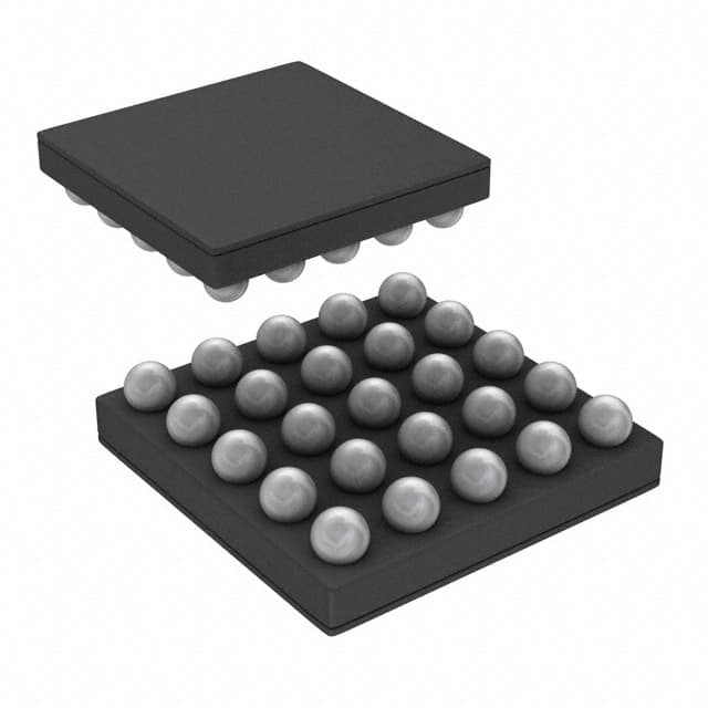
- Part No.:
- LP8552TLX-E04/NOPB
- Manufacturer:
- Texas Instruments
- Category:
- LED Drivers
- Package:
- 25-WFBGA, DSBGA
- Datasheet:
-
 LP8552TLX-E04/NOPB.pdf
- Description:
- IC LED DRVR RGLTR PWM 25DSBGA
- Quantity:
- Payment:

- Shipping:

Inventory:3,703
Please send an inquiry. Send us your inquiry, and we will respond immediately.
Product details
Overview
LP8552TLX-E04/NOPB from Texas Instruments is a high-efficiency, six-channel white LED backlight driver IC with integrated 44-V boost converter, adaptive output voltage control, and I²C/PWM dual-brightness interface. It delivers up to 210 mA per channel (400 mA peak), supports 2.7–22 V input, and targets notebook LCD backlight systems requiring precise dimming, thermal safety, and VSYNC synchronization.
For engineers reviewing the LP8552TLX-E04/NOPB datasheet, LP8552TLX-E04/NOPB pinout, LP8552TLX-E04/NOPB application, or LP8552TLX-E04/NOPB equivalent, this page provides verified technical context, real-world pin functions, confirmed efficiency curves, validated alternative options, and supply-chain support details specific to the E04 variant's EEPROM configuration and DSBGA-25 package.
Technical Context
The LP8552TLX-E04/NOPB implements an adaptive boost architecture that dynamically adjusts output voltage based on real-time LED string voltage monitoring-minimizing power loss across varying forward voltages. Its internal 5-MHz oscillator feeds a programmable PLL, enabling VSYNC-synchronized PWM generation (58–55 kHz) or fixed-frequency operation at 156/312/625/1250 kHz.
It integrates six independent current sinks with 8-bit programmable current setting (via RISET resistor and EEPROM), 13-bit PWM resolution (with dithering), and proprietary Phase-Shift PWM to reduce peak inductor current and audible noise. Fault detection covers LED open/short, overtemperature (150°C shutdown), overvoltage (44 V max), and undervoltage lockout (configurable thresholds: 2.7 V, 5.4 V, or 8.1 V).
Key Specifications
| Parameter | Value and Actual Design Meaning |
|---|---|
| Input Voltage Range | 2.7 V to 22 V - supports single- to 5-cell Li-ion batteries without external regulators. |
| Boost Output Voltage | Up to 44 V - enables driving long LED strings (e.g., 10+ white LEDs in series) with adaptive headroom control. |
| LED Channel Current | 210 mA typical per channel (400 mA peak) - sufficient for medium-size notebook panels (13–15.6 inch). |
| PWM Resolution | 13-bit true resolution with dithering - achieves smooth brightness transitions without visible stepping during fade effects. |
| Switching Frequency | 156/312/625/1250 kHz selectable - higher frequencies allow smaller external inductors (e.g., 15 µH) and reduced EMI. |
| Thermal Protection | 150°C junction shutdown with 130°C hysteresis - prevents permanent damage during sustained high-power operation. |
| VSYNC Sync Range | 58–55,000 Hz - locks to standard display refresh rates (60 Hz) and accommodates variable-refresh-rate panels. |
Pinout & Package
LP8552TLX-E04/NOPB uses a 25-pin DSBGA (YZR) package measuring 2.49 mm × 2.49 mm with 0.4-mm pitch. The package features dedicated ground domains (GND_SW, GND_S, GND_L) for noise isolation between boost, logic, and LED return paths.
| Pin/Terminal | Circuit Role | Design Meaning |
|---|---|---|
| A1, A2, B1, B2, E4 | GND_SW / GND_S / GND_L | Separate ground returns isolate boost switching noise (GND_SW), digital logic (GND_S), and LED current sink (GND_L) to prevent coupling. |
| C1 | VIN | Main power input (2.7–22 V); powers boost stage and internal LDO - requires 10 µF ceramic input capacitor. |
| D1 | VLDO | 5-V LDO output; supplies external circuitry or serves as reference when VIN < 5.5 V - bypassed with 1 µF ceramic. |
| A3 | EN | Active-high enable; must be pulled high to activate boost and LED drivers - supports system-level power sequencing. |
| A4 | PWM | Analog brightness control input; accepts 0.1–25 kHz PWM signal - internally measured for duty cycle and used for phase-shifted output. |
| B3 | ISET | Current-setting node; connects to RISET resistor (e.g., 16 kΩ sets ~23 mA) - floating if EEPROM current config is used. |
| C5, D5, E1–E5 | OUT1–OUT6 | Six constant-current sinks; each drives one LED string - supports open/short fault detection per channel. |
| C3 | FAULT | Open-drain fault indicator; asserts low on LED fault, overtemp, or overvoltage - simplifies system-level error reporting. |
Key Features
| Feature | Design Value |
|---|---|
| Adaptive Boost Voltage Control | Monitors LED string voltage in real time and minimizes VOUT to only what's required - reduces power loss by up to 15% vs. fixed-output designs. |
| VSYNC-Synchronized PWM | Uses internal PLL to lock LED dimming frequency precisely to display vertical sync - eliminates flicker and beat interference in video playback. |
| Phase-Shift PWM Mode | Staggers turn-on timing across OUT1–OUT6 channels - cuts peak boost inductor current by ~30%, allowing smaller 15 µH inductors and quieter operation. |
| EEPROM-Configurable Parameters | Stores 8-bit current settings, PWM resolution (8–13 bit), dither mode, thermal trip point, and slope rate - eliminates need for external configuration components. |
| Multi-Level Fault Protection | Detects open/short LED faults, overtemperature (150°C shutdown), input UVLO (configurable thresholds), and boost overvoltage - ensures robust field reliability. |
Applications
| Notebook LCD Backlight | Industrial Panel Display |
|---|---|
Use Scenario: Driving 6-string white LED backlight for 14-inch notebook panel with 23 mA per string and 60 Hz VSYNC input. IC Role / Device Role / Timing Role: Primary LED driver with adaptive boost, VSYNC-locked PWM dimming, and thermal derating at >110°C junction. Use Value: Achieves >94% efficiency at 12 V input and 35 V boost, reduces audible coil whine via phase-shift PWM, and maintains luminance stability across battery discharge. |
Use Scenario: Backlight control for ruggedized 10.1-inch industrial HMI with extended temperature range (−30°C to 85°C ambient). IC Role / Device Role / Timing Role: Constant-current LED driver with EEPROM-stored thermal thresholds and open-fault detection for unattended operation. Use Value: Enables fail-safe shutdown on LED string failure, supports wide-input operation down to 2.7 V, and retains configuration through power cycles without external memory. |
| Medical Diagnostic Monitor | Automotive Infotainment Display |
Use Scenario: High-reliability backlight for 15.6-inch medical imaging display requiring consistent luminance and fault logging. IC Role / Device Role / Timing Role: Precision current sink with 0.5% matching across channels and I²C-accessible fault registers for diagnostic reporting. Use Value: Ensures uniform brightness across full screen, logs open-circuit events to host MCU, and maintains ±3% current accuracy over temperature. |
Use Scenario: LED backlight in automotive infotainment unit with CAN-based system controller and 12 V nominal supply. IC Role / Device Role / Timing Role: LED driver with UVLO set to 5.4 V to prevent brownout during cold cranking, and FAULT pin tied to microcontroller interrupt. Use Value: Survives load-dump transients up to 24 V, provides immediate fault signaling for dashboard warning, and supports PWM dimming synchronized to display frame rate. |
Equivalent & Alternatives
The following parts are listed as comparable options for similar LED backlight driver applications.
| Alternative Part | Technical Difference | Application Difference | Selection Advice |
|---|---|---|---|
| LP8557TLE/NOPB | Same DSBGA-25 package; adds analog current control via ISET pin and enhanced EEPROM flexibility but lacks VSYNC sync capability. | Preferred where system lacks VSYNC signal but requires fine-grained analog dimming alongside PWM. | Select LP8557TLE/NOPB only if VSYNC synchronization is unnecessary and analog current tuning is prioritized over phase-shift noise reduction. |
| TPS61165DRVR | Single-channel, 40-V boost LED driver in 6-pin WSON; no integrated EEPROM, no VSYNC sync, no multi-channel current matching. | Suitable for cost-sensitive, single-string applications where board space is constrained and system-level MCU handles all dimming logic. | Choose TPS61165DRVR only for simple single-string designs without thermal derating, fault logging, or multi-string synchronization requirements. |
Compared with LP8552TLX-E04/NOPB, LP8557TLE/NOPB trades VSYNC sync for expanded analog control, while TPS61165DRVR sacrifices channel count, intelligence, and protection for minimal footprint and BOM cost - neither matches the E04 variant's balance of integration, reliability, and display-timing precision.
Availability
LP8552TLX-E04/NOPB is available at Aetrix Electronics and suitable for notebook backlight design, industrial HMI development, and medical display manufacturing requiring stable component supply, long-term lifecycle assurance, and traceable sourcing.
Supply support for LP8552TLX-E04/NOPB includes scheduled delivery planning, volume procurement assistance, BOM continuity management, traceable sourcing, and lifecycle availability coordination for OEM customers, industrial embedded developers, connected-device designers, and electronics production programs.
Manufacturer
Texas Instruments is a global semiconductor leader specializing in analog, embedded processing, and power management ICs, with decades of expertise in power-efficient LED driver architectures.
The LP8552 product line was engineered specifically for high-efficiency, thermally robust LCD backlight control in portable computing - emphasizing adaptive voltage regulation, VSYNC synchronization, and integrated fault resilience for battery-powered systems.
FAQ
What is the key functional difference between LP8552TLX-E04/NOPB and other LP8552 variants like E00 or E05?
The LP8552TLX-E04/NOPB is factory-configured with EEPROM address A0h = 01111111, A1h = 11110101, and A5h = 01000101 - defining default settings for PWM resolution (13-bit), phase-shift PWM enabled, and thermal derating threshold at 110°C. Unlike E00 (no dithering) or E05 (lower current limit), the E04 variant prioritizes smooth dimming and thermal safety for mid-to-high brightness notebook use cases. LP8552TLX-E04/NOPB retains full I²C reprogrammability post-deployment.
Does LP8552TLX-E04/NOPB require external resistors for basic operation, or can it run from EEPROM defaults alone?
LP8552TLX-E04/NOPB can operate using only its factory-programmed EEPROM defaults - including 23 mA LED current, 13-bit PWM resolution, and 625 kHz boost frequency - eliminating need for RISET or RFSET resistors. However, ISET and FSET pins remain accessible for fine-tuning: RISET adjusts current (e.g., 16 kΩ = 23 mA), and RFSET sets PWM frequency (e.g., 120 kΩ = 9.6 kHz). LP8552TLX-E04/NOPB supports both resistor-based and register-based configuration.
How does the Phase-Shift PWM mode in LP8552TLX-E04/NOPB reduce audible noise compared to standard PWM?
LP8552TLX-E04/NOPB staggers the turn-on timing of its six LED outputs by fixed phase offsets - distributing the boost converter's current demand across the PWM period instead of concentrating it at one instant. This lowers peak inductor current by up to 30%, reducing mechanical vibration in ferrite-core inductors and eliminating 1–20 kHz coil whine. LP8552TLX-E04/NOPB implements this natively without external timing components or firmware overhead.
Can LP8552TLX-E04/NOPB drive LED strings with different forward voltages simultaneously?
Yes - LP8552TLX-E04/NOPB's adaptive boost control monitors each LED string's cathode voltage via the OUTx pins and dynamically adjusts VOUT to the minimum level needed for the highest-Vf string. This allows mixed-string configurations (e.g., 8-LED and 10-LED strings) without overvoltage stress on lower-Vf strings. LP8552TLX-E04/NOPB maintains individual current regulation per channel regardless of inter-string Vf variance.
What fault conditions trigger the FAULT pin on LP8552TLX-E04/NOPB, and how is recovery handled?
The FAULT pin on LP8552TLX-E04/NOPB asserts low for LED open/short, junction temperature ≥150°C, VIN below UVLO threshold (set to 5.4 V for E04), or boost overvoltage ≥44 V. Recovery is automatic: after fault removal (e.g., cooling below 130°C or restoring VIN), LP8552TLX-E04/NOPB resumes operation within 6 ms. All fault states are also readable via I²C register 0x1A, enabling host MCU diagnostics without relying solely on the FAULT pin.
LP8552TLX-E04/NOPB Specifications
- Product attributes
- Attribute value
- Manufacturer:
- Texas Instruments
- Series:
- -
- Package/Case:
- 25-WFBGA, DSBGA
- Packaging:
- Tape & Reel (TR)
- Product Status:
- Active
- Type:
- DC DC Regulator
- Topology:
- Step-Up (Boost)
- Internal Switch(s):
- Yes
- Number of Outputs:
- 6
- Voltage - Supply (Min):
- 2.7V
- Voltage - Supply (Max):
- 22V
- Voltage - Output:
- 40V
- Current - Output / Channel:
- 450mA
- Frequency:
- -
- Dimming:
- PWM
- Applications:
- Backlight
- Operating Temperature:
- -40°C ~ 85°C (TA)
- Grade:
- -
- Qualification:
- -
- Mounting Type:
- Surface Mount
- Supplier Device Package:
- 25-DSBGA
LP8552TLX-E04/NOPB FAQ
1.How can I place an order for LP8552TLX-E04/NOPB through Aetrix?
Please submit a Request for Quotation (RFQ) for LP8552TLX-E04/NOPB on Aetrix. Our sales agent will provide a competitive quotation and guide you through the order confirmation once you accept the terms.
2.Are the price and stock information for LP8552TLX-E04/NOPB reliable?
The price and inventory of LP8552TLX-E04/NOPB are updated periodically and may fluctuate due to market conditions. Stock and pricing data are typically refreshed every 24 hours. Quotation validity for LP8552TLX-E04/NOPB is usually 5 days.
3.What payment methods are accepted for LP8552TLX-E04/NOPB?
We accept Wire Transfer, PayPal, Credit Card, Western Union, MoneyGram, and Escrow for LP8552TLX-E04/NOPB transactions.
Note: Certain payment methods may incur a processing fee.
4.How is shipping managed for LP8552TLX-E04/NOPB?
LP8552TLX-E04/NOPB orders can be shipped via leading logistics carriers, including DHL, UPS, FedEx, TNT, or Registered Mail.
Once your LP8552TLX-E04/NOPB order is processed, you will receive an email with the shipment details and tracking number.
Note: Tracking information may take up to 24 hours to appear. Express delivery typically takes 3–5 business days.
5.How can I obtain technical support or documentation for LP8552TLX-E04/NOPB?
For technical support, including LP8552TLX-E04/NOPB datasheets, pinout diagrams, or application guidance, please contact our engineering support team. They can provide detailed documentation and assistance for your LP8552TLX-E04/NOPB requirements.
6.How does Aetrix verify that LP8552TLX-E04/NOPB is sourced from the original manufacturer or authorized distributors?
All LP8552TLX-E04/NOPB products on Aetrix are procured from qualified distributors and authorized channels. Our dedicated quality assurance team conducts strict verification, including traceability checks and, if necessary, third-party testing. This ensures that LP8552TLX-E04/NOPB meets industry standards.
7.What is the process for return or replacement of LP8552TLX-E04/NOPB?
All LP8552TLX-E04/NOPB units undergo pre-shipment inspection (PSI). If there is an issue with LP8552TLX-E04/NOPB, returns or replacements are accepted under the following conditions:
1.Quantity discrepancies, incorrect items, or visible external defects (such as breakage or corrosion), acknowledged by Aetrix.
2.The issue is reported within 90 days of delivery.
3.The LP8552TLX-E04/NOPB part is unused and in its original packaging.
Return procedure for LP8552TLX-E04/NOPB:
1.Submit a request within 90 days.
2.Obtain a Return Material Authorization (RMA) from Aetrix.
LP8552TLX-E04/NOPB Tags

-
BCR402RE6327HTSA1
Infineon Technologies

-
BCR430UXTSA2
Infineon Technologies

-
BCR420UE6433HTMA1
Infineon Technologies
-
BCR420UE6327HTSA1
Infineon Technologies
-
BCR421UE6327HTSA1
Infineon Technologies

-
LYT1604D-TL
Power Integrations

-
HV9910CLG-G
Microchip Technology

-
CL2N8-G
Microchip Technology

-
BCR420UW6-7
Diodes Incorporated
-
BCR421UW6-7
Diodes Incorporated

-
BCR420UFD-7
Diodes Incorporated
-
BCR421UFD-7
Diodes Incorporated
Tech Hub

A practical engineering guide to 3.3V and 5V logic compatibility, input thresholds, resistor dividers, translator ICs, MOSFET level shifting, I2C pull-ups, timing limits and power-sequencing risks.

The 74HC595 uses push-pull logic outputs, while the TPIC6B595 uses 50 V open-drain DMOS sinks for higher-power loads. This guide compares timing, current limits, 3.3 V interfacing, load wiring, thermal…

The 74HC595 converts serial data into eight stable parallel outputs. This guide covers pin functions, shift and storage timing, OE and MR behavior, drive-current limits, cascading, voltage compatibilit…

A technical comparison of level-sensitive latches and edge-triggered flip-flops, covering timing windows, setup and hold limits, master–slave operation, time borrowing, race-through, HDL inference and…

A D latch stores one bit while Enable controls when data can pass. This reference covers gate-level operation, truth tables, transparency, setup and hold timing, LE versus OE, common ICs and practical …

An SR latch stores one bit through cross-coupled feedback. This engineering reference covers NOR and NAND implementations, truth tables, forbidden-state recovery, gated operation, switch debouncing, fa…

Latch circuits retain one bit through feedback. This technical reference covers SR and D latches, truth tables, transparency, timing limits, latch-versus-flip-flop behavior, applications and common log…

An engineering guide to LED driver operation, constant-current and constant-voltage outputs, linear and switching topologies, dimming, IC selection, calculations, replacement compatibility, and fault c…

Operational amplifier guide covering op amp basics, feedback, ideal vs real op amps, common configurations, buffer circuits, offset, bias current, gain-bandwidth, slew rate, rail-to-rail limits and sel…

Jumper cables guide covering safe connection order, red and black clamp placement, final ground connection, cable gauge, length, clamp quality, copper vs CCA cables, jump starter comparison and battery…


