
 My Inquiry
 My Account


Microchip Technology LPC47M112-MW
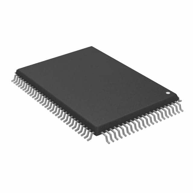
- Part No.:
- LPC47M112-MW
- Manufacturer:
- Microchip Technology
- Category:
- Specialized
- Package:
- 100-BQFP
- Datasheet:
-
 LPC47M112-MW.pdf
- Description:
- IC INTERFACE SPECIALIZED 100QFP
- Quantity:
- Payment:

- Shipping:

Inventory:3,440
Please send an inquiry. Send us your inquiry, and we will respond immediately.
Product details
Overview
LPC47M112-MW from Microchip Technology is a 3.3V (5V-tolerant) LPC-interface Super I/O controller implementing PC98/PC99 compliance, ACPI 1.0 support, and integrated fan speed control with two tachometer inputs. It integrates a licensed CMOS 765B floppy disk controller, dual NS16C550A-compatible UARTs with 16-byte FIFOs, IEEE 1284 EPP/ECP parallel port with ChiProtect, and 8042-compatible keyboard/mouse interface - deployed in legacy industrial PCs and embedded x86 systems requiring consolidated I/O management.
For engineers reviewing the LPC47M112-MW datasheet, LPC47M112-MW pinout, LPC47M112-MW application, or LPC47M112-MW equivalent, this page delivers verified functional scope, validated pin assignments, confirmed power architecture (VCC/VTR dual-rail), exact LPC bus timing compliance, and real-world substitution guidance for end-of-life migration and board-level redesign.
Technical Context
The LPC47M112-MW implements a multiplexed LPC bus (LAD[3:0], nLFRAME, nLDRQ) compliant with Intel's LPC Interface Specification v1.0, supporting serialized IRQ and PME signaling for PCI-based host systems. Its internal architecture integrates discrete functional blocks - including a true CMOS 765B floppy controller core, advanced digital data separator with programmable precompensation, and dual UARTs with independent 16-byte FIFOs - all managed via shared configuration registers accessible through ISA Plug-and-Play register sets.
Power management operates across three rails: VCC (3.3V main logic), VTR (3.3V trickle supply enabling wake-on-keyboard/mouse/fan events during VCC removal), and VREF (reference voltage). The device supports multiple low-power-down modes via sophisticated power control circuitry (PCC), with wake-up event routing to nIO_PME and nIO_SMI outputs, and hardware-level SMI assertion for system management firmware intervention.
Key Specifications
| Parameter | Value and Actual Design Meaning |
|---|---|
| LPC Interface | Fully compliant with Intel LPC v1.0 spec; uses LAD[3:0]/nLFRAME/nLDRQ; supports serialized IRQ and PME handshake for PCI host integration. |
| Floppy Controller | Licensed CMOS 765B core; 100% IBM PC/AT compatible; supports two drives; includes 16-byte FIFO, vertical recording, overrun/under-run detection. |
| UARTs | Two NS16C550A-compatible UARTs; each with 16-byte TX/RX FIFO; supports up to 460 kbps; full modem control (RTS/CTS/DTR/DSR/RI/DCD). |
| Parallel Port | IEEE 1284-compliant multi-mode port: Standard, EPP 1.7/1.9, and ECP; includes ChiProtect circuitry; 17-pin interface with bidirectional data and status lines. |
| Fan Control | Two dedicated fan speed control outputs (GP32/FAN2, GP33/FAN1) and two tachometer inputs (GP30/FAN_TACH2, GP31/FAN_TACH1); supports RPM monitoring and PWM-driven thermal regulation. |
| Power Architecture | 3.3V VCC operation with 5V-tolerant non-LPC pins; VTR rail enables wake-on-event functionality (keyboard, mouse, UART RI, GPIO) during VCC removal. |
| Package | 100-pin RoHS-compliant QFP, 3.2 mm body height; pin pitch 0.5 mm; footprint matches standard 100-pin QFP land pattern. |
Pinout & Package
100-pin QFP (3.2 mm height, 0.5 mm pitch), RoHS-compliant, with exposed thermal pad not electrically connected. Pin functions are multiplexed across LPC interface, FDD, UART, parallel, keyboard/mouse, infrared, game port, and 37 GPIOs - all defined in Microchip DS00002516A.
| Pin/Terminal | Circuit Role | Design Meaning |
|---|---|---|
| LAD[3:0] | LPC Multiplexed Bus | Time-multiplexed address/data/command lines; require external latch and timing coordination per LPC spec. |
| nLFRAME | LPC Frame Signal | Indicates start of LPC transaction cycle; active-low synchronous with PCI_CLK; defines command phase boundary. |
| GP33/FAN1 | Fan Speed Control Output | Open-drain or push-pull output (configurable); drives external fan PWM input or DC voltage level; 12 mA sink capability. |
| GP31/FAN_TACH1 | Fan Tachometer Input | Schmitt-trigger input; accepts TTL/CMOS pulses from fan tach sensor; used for closed-loop RPM measurement and alarm generation. |
| nIO_PME | Power Management Event Output | Open-drain active-low signal asserted by VTR-powered logic on wake events (e.g., keyboard press, UART RI); requires external pull-up. |
| KDAT / KCLK | Keyboard Interface | Bi-directional 8042-compatible serial data/clock pair; require external 10 kΩ pull-ups; support PS/2 keyboard and mouse protocols. |
Key Features
| Feature | Design Value |
|---|---|
| Integrated Floppy Controller | True CMOS 765B core with 100% IBM compatibility, 16-byte FIFO, vertical format support, and hardware overflow/underflow detection - eliminates need for external FDC IC. |
| Dual High-Speed UARTs | NS16C550A-compatible with 16-byte FIFOs per channel, baud rates up to 460 kbps, and full modem handshaking - enables robust serial console and modem connectivity without external UARTs. |
| ChiProtect Parallel Port | Hardware-level overvoltage protection on all parallel port pins (PD0–PD7, BUSY, SLCT, etc.) - prevents damage from hot-plug or miswired peripherals in industrial environments. |
| VTR-Powered Wake Logic | Dedicated 3.3V trickle rail powers wake sources (keyboard, mouse, UART RI, GPIOs, fan tach) independently of VCC - enables reliable resume-from-standby in headless embedded systems. |
| LPC Bus Integration | Reduces motherboard pin count vs. ISA; supports ACPI 1.0, SMI, PME, and Plug-and-Play - simplifies chipset-to-I/O communication in space-constrained x86 designs. |
Applications
| Industrial PC Baseboard | Legacy Embedded x86 System |
|---|---|
Use Scenario: Motherboard for ruggedized factory-floor PC running Windows CE or DOS-based HMI software. IC Role / Device Role / Timing Role: Centralized I/O hub managing floppy boot, serial debug ports, parallel printer interface, and thermal monitoring via onboard fans. Use Value: Reduces BOM count by integrating FDC, UARTs, parallel port, keyboard controller, and fan control - lowering PCB layer count and test complexity. |
Use Scenario: Fanless embedded controller for railway signaling cabinet with legacy peripheral requirements. IC Role / Device Role / Timing Role: Provides wake-on-serial (UART RI), secure parallel port access, and tachometer-based thermal shutdown - all operable under VTR-only standby mode. Use Value: Enables zero-power standby with deterministic wake latency (<50 ms) using only VTR rail, eliminating battery-backed RTC dependency. |
| Medical Diagnostic Equipment | Point-of-Sale Terminal |
Use Scenario: Ultrasound machine requiring floppy-based calibration update, IR printer interface, and dual serial ports for service diagnostics. IC Role / Device Role / Timing Role: Hosts IrDA 1.0 infrared port (IRTX2/IRRX2), MPU-401 MIDI UART for audio feedback, and dual UARTs for service/debug channels. Use Value: Single-chip support for FDA-regulated field-service interfaces - avoids qualification of multiple discrete I/O components. |
Use Scenario: Retail terminal with PS/2 keyboard/mouse, parallel receipt printer, and game port for barcode scanner emulation. IC Role / Device Role / Timing Role: Delivers 8042-compatible keyboard/mouse interface, ChiProtect-secured parallel port, and dual game port signals (J1B1/J1B2, J2B1/J2B2). Use Value: Prevents ESD-induced printer lockup via ChiProtect; ensures keyboard responsiveness during high-noise retail EM environment. |
Equivalent & Alternatives
The following parts are listed as comparable options for similar Super I/O controller applications.
| Alternative Part | Technical Difference | Application Difference | Selection Advice |
|---|---|---|---|
| Winbond W83627HF | ISA-based interface (not LPC); lacks VTR rail and true 32.768 kHz tachometer clock source; no ChiProtect on parallel port. | Requires ISA slot or bridge; cannot support VCC-off wake events; parallel port less robust in noisy environments. | Select only if migrating from ISA architecture and VTR-powered standby is unnecessary. |
| Nuvoton NCT6776D | LPC interface with modern ACPI 5.0 support; integrated hardware monitor (temp/volt/current); no floppy controller; no game port. | Targets modern BIOS/UEFI platforms; excludes legacy floppy and joystick support; adds digital thermal sensing. | Choose for new designs needing hardware monitoring and ACPI 5.0, but avoid when floppy boot or dual game port are mandatory. |
Compared with LPC47M112-MW, the W83627HF requires ISA infrastructure and lacks VTR-enabled wake reliability, while the NCT6776D drops floppy and game port support to add hardware monitoring - making LPC47M112-MW uniquely suited for legacy x86 systems requiring full PC98/PC99 peripheral consolidation.
Availability
LPC47M112-MW is available at Aetrix Electronics and suitable for industrial PC baseboards, legacy embedded x86 systems, and medical diagnostic equipment requiring stable component supply, long-term lifecycle assurance, and RoHS-compliant 100-pin QFP packaging.
Supply support for LPC47M112-MW includes scheduled delivery planning, volume procurement assistance, BOM continuity management, traceable sourcing, and lifecycle availability coordination for OEM customers, industrial embedded developers, connected-device designers, and electronics production programs.
Manufacturer
Microchip Technology is a global semiconductor company specializing in microcontrollers, analog devices, and interface ICs, with deep heritage in PC I/O and embedded control solutions.
The LPC47M112-MW belongs to Microchip's Super I/O product line, designed specifically to consolidate legacy PC peripheral functions - floppy, serial, parallel, keyboard, fan control, and power management - into a single LPC-connected device for cost-sensitive, space-constrained x86 platforms.
FAQ
What is the operating voltage range and tolerance for LPC47M112-MW?
LPC47M112-MW operates at nominal 3.3V VCC and is 5V-tolerant on all non-LPC pins (max 5.5V input). LPC interface pins (LAD[3:0], nLFRAME, nLDRQ, nLPCPD, nPCI_RESET, PCI_CLK, SER_IRQ) are strictly 3.3V-only and comply with PCI 3.3V DC specifications. VTR rail must be 3.3V to enable wake-on-event functionality during VCC removal.
Does LPC47M112-MW support floppy disk boot functionality?
Yes, LPC47M112-MW includes a licensed CMOS 765B floppy disk controller core that is 100% IBM PC/XT and PC/AT compatible, supports vertical recording format, detects overrun/under-run conditions, and provides direct drive support for two floppy drives - enabling full BIOS-level floppy boot capability in legacy x86 systems.
How does the VTR rail function in LPC47M112-MW, and what features depend on it?
The VTR rail powers wake-on-event logic (keyboard, mouse, UART RI, GPIOs, fan tachometers) and PME configuration registers when VCC is removed. Features requiring VTR include wake-on-specific-key, LED blink timing, and fan tachometer measurement under standby. If VTR is tied to VCC, these functions remain active only during normal operation - not during VCC-off states.
Is LPC47M112-MW pin-compatible with other Microchip Super I/O devices like LPC47B272?
No, LPC47M112-MW is not pin-compatible with LPC47B272. While both are LPC-interface Super I/O controllers, LPC47B272 uses a 128-pin QFP package and includes additional features (e.g., second floppy controller, enhanced power management) with different pin mapping, buffer types, and register layout - requiring PCB redesign for substitution.
What parallel port modes does LPC47M112-MW support, and how is ChiProtect implemented?
LPC47M112-MW supports Standard (PC/XT/AT/PS/2), EPP 1.7/1.9, and ECP modes per IEEE 1284. ChiProtect is integrated hardware overvoltage protection on all parallel port pins (PD0–PD7, BUSY, SLCT, PE, nACK, nERROR, nALF, nSTROBE), clamping transients to safe levels without external components - critical for industrial printer interfacing.
LPC47M112-MW Specifications
- Product attributes
- Attribute value
- Manufacturer:
- Microchip Technology
- Series:
- -
- Package/Case:
- 100-BQFP
- Packaging:
- Tray
- Product Status:
- Obsolete
- Applications:
- -
- Interface:
- LPC
- Voltage - Supply:
- 3.3V
- Supplier Device Package:
- 100-QFP (14x20)
- Grade:
- -
- Qualification:
- -
- Mounting Type:
- Surface Mount
LPC47M112-MW FAQ
1.How can I place an order for LPC47M112-MW through Aetrix?
Please submit a Request for Quotation (RFQ) for LPC47M112-MW on Aetrix. Our sales agent will provide a competitive quotation and guide you through the order confirmation once you accept the terms.
2.Are the price and stock information for LPC47M112-MW reliable?
The price and inventory of LPC47M112-MW are updated periodically and may fluctuate due to market conditions. Stock and pricing data are typically refreshed every 24 hours. Quotation validity for LPC47M112-MW is usually 5 days.
3.What payment methods are accepted for LPC47M112-MW?
We accept Wire Transfer, PayPal, Credit Card, Western Union, MoneyGram, and Escrow for LPC47M112-MW transactions.
Note: Certain payment methods may incur a processing fee.
4.How is shipping managed for LPC47M112-MW?
LPC47M112-MW orders can be shipped via leading logistics carriers, including DHL, UPS, FedEx, TNT, or Registered Mail.
Once your LPC47M112-MW order is processed, you will receive an email with the shipment details and tracking number.
Note: Tracking information may take up to 24 hours to appear. Express delivery typically takes 3–5 business days.
5.How can I obtain technical support or documentation for LPC47M112-MW?
For technical support, including LPC47M112-MW datasheets, pinout diagrams, or application guidance, please contact our engineering support team. They can provide detailed documentation and assistance for your LPC47M112-MW requirements.
6.How does Aetrix verify that LPC47M112-MW is sourced from the original manufacturer or authorized distributors?
All LPC47M112-MW products on Aetrix are procured from qualified distributors and authorized channels. Our dedicated quality assurance team conducts strict verification, including traceability checks and, if necessary, third-party testing. This ensures that LPC47M112-MW meets industry standards.
7.What is the process for return or replacement of LPC47M112-MW?
All LPC47M112-MW units undergo pre-shipment inspection (PSI). If there is an issue with LPC47M112-MW, returns or replacements are accepted under the following conditions:
1.Quantity discrepancies, incorrect items, or visible external defects (such as breakage or corrosion), acknowledged by Aetrix.
2.The issue is reported within 90 days of delivery.
3.The LPC47M112-MW part is unused and in its original packaging.
Return procedure for LPC47M112-MW:
1.Submit a request within 90 days.
2.Obtain a Return Material Authorization (RMA) from Aetrix.
LPC47M112-MW Tags

-
NVT4857UKAZ
NXP Semiconductors

-
TCA8418RTWR
Texas Instruments

-
PCA9546APWR
Texas Instruments

-
MD0100N8-G
Microchip Technology

-
PCA9548APW,118
NXP Semiconductors

-
PCA9540BDP,118
NXP Semiconductors

-
PCA9548APWR
Texas Instruments

-
PCA9546APW,118
NXP Semiconductors

-
PTN3360DBS,518
NXP Semiconductors

-
PCA9546ABS,118
NXP Semiconductors

-
PCA9518PWR
Texas Instruments

-
PCA9545APW,118
NXP Semiconductors
Tech Hub

TTL and CMOS logic families differ in thresholds, loading, output drive, power and timing. This engineering guide compares 74HC and 74HCT, calculates noise margins and checks 3.3 V/5 V compatibility.

A practical engineering guide to 3.3V and 5V logic compatibility, input thresholds, resistor dividers, translator ICs, MOSFET level shifting, I2C pull-ups, timing limits and power-sequencing risks.

The 74HC595 uses push-pull logic outputs, while the TPIC6B595 uses 50 V open-drain DMOS sinks for higher-power loads. This guide compares timing, current limits, 3.3 V interfacing, load wiring, thermal…

The 74HC595 converts serial data into eight stable parallel outputs. This guide covers pin functions, shift and storage timing, OE and MR behavior, drive-current limits, cascading, voltage compatibilit…

A technical comparison of level-sensitive latches and edge-triggered flip-flops, covering timing windows, setup and hold limits, master–slave operation, time borrowing, race-through, HDL inference and…

A D latch stores one bit while Enable controls when data can pass. This reference covers gate-level operation, truth tables, transparency, setup and hold timing, LE versus OE, common ICs and practical …

An SR latch stores one bit through cross-coupled feedback. This engineering reference covers NOR and NAND implementations, truth tables, forbidden-state recovery, gated operation, switch debouncing, fa…

Latch circuits retain one bit through feedback. This technical reference covers SR and D latches, truth tables, transparency, timing limits, latch-versus-flip-flop behavior, applications and common log…

An engineering guide to LED driver operation, constant-current and constant-voltage outputs, linear and switching topologies, dimming, IC selection, calculations, replacement compatibility, and fault c…

Operational amplifier guide covering op amp basics, feedback, ideal vs real op amps, common configurations, buffer circuits, offset, bias current, gain-bandwidth, slew rate, rail-to-rail limits and sel…


