
 My Inquiry
 My Account


Analog Devices Inc. LT3506AEFE#PBF
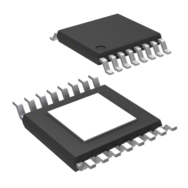
- Part No.:
- LT3506AEFE#PBF
- Manufacturer:
- Analog Devices Inc.
- Package:
- 16-TSSOP (0.173", 4.40mm Width) Exposed Pad
- Datasheet:
-
 LT3506AEFE#PBF.pdf
- Description:
- IC REG BUCK ADJ 1.6A DL 16TSSOP
- Quantity:
- Payment:

- Shipping:

Inventory:326
Please send an inquiry. Send us your inquiry, and we will respond immediately.
Product details
Overview
LT3506AEFE#PBF from Analog Devices (formerly Linear Technology) is a dual monolithic current-mode PWM step-down DC/DC converter with internal 2A bipolar NPN power switches, delivering two independent 1.6A outputs. It operates at 1.1MHz switching frequency, supports 3.6V–25V input, regulates to 0.8V feedback reference (±1%), and features anti-phase operation to reduce input ripple. Used in DSP power supplies and distributed power regulation where compact dual-rail generation is required.
For engineers reviewing the LT3506AEFE#PBF datasheet, LT3506AEFE#PBF pinout, LT3506AEFE#PBF application, or LT3506AEFE#PBF equivalent, key selection considerations include its 1.1MHz fixed-frequency operation, independent RUN/SS and PGOOD pins per channel, thermal shutdown and frequency foldback protection, and compatibility with ceramic output capacitors for low-ripple 1.6A dual-rail designs.
Technical Context
The LT3506AEFE#PBF implements constant-frequency current-mode control with shared master oscillator and independent slave oscillators per channel, enabling precise anti-phase (180°) switching to minimize input capacitor RMS current. Each regulator uses an internal 800mV reference and error amplifier with transconductance of 350μMhos to drive the VC pin, which directly controls peak switch current.
It integrates bipolar NPN power switches with typical VCE(SAT) of 210mV at 1A and supports external BOOST capacitor/diode networks to ensure full saturation. Frequency foldback activates below 0.4V on FB pins during overload, reducing switch current and thermal stress while maintaining regulation under short-circuit conditions.
Key Specifications
| Parameter | Value and Actual Design Meaning |
|---|---|
| Switching Frequency | 1.1MHz - enables use of sub-3mm inductors (e.g., 2.2μH) and <10μF ceramic output caps for ultra-compact layout |
| Input Voltage Range | 3.6V to 25V - supports 4-cell Li-ion, 5V/12V/24V rails, and unregulated wall adapters without pre-regulation |
| Output Current per Channel | 1.6A continuous - sustained across full temperature range with proper thermal pad soldering and PCB copper area |
| Feedback Reference Voltage | 0.800V ±1% - sets output accuracy; allows precise 1.2V, 1.8V, 3.3V, or 5V rails using standard 1% resistor dividers |
| Power Good Threshold | 720mV rising on FB - asserts open-collector PGOOD when output reaches 90% of target, enabling safe sequencing with microcontrollers |
| Shutdown Current | 30μA max - ensures ultra-low system standby power when both RUN/SS pins are pulled low |
| Thermal Shutdown | 125°C junction - protects device during overload or poor heatsinking; auto-recovery after cooldown |
Pinout & Package
LT3506AEFE#PBF is housed in a 16-lead plastic TSSOP narrow package (FE) with exposed thermal pad (Pin 17 = GND). The package measures 5mm × 4.4mm × 1.1mm and requires soldering of the exposed pad to PCB ground plane for thermal and electrical integrity (θJA = 45°C/W).
| Pin/Terminal | Circuit Role | Design Meaning |
|---|---|---|
| BOOST1 (1), BOOST2 (8) | Bootstrap drive supply | Connects via diode + capacitor to VOUT or VIN to generate >VIN gate drive for internal NPN switches |
| SW1 (2), SW2 (7) | Switch node output | Drives external inductor and catch diode; high dv/dt node requiring tight loop layout and ground shielding |
| VIN1 (3,4), VIN2 (5,6) | Input power supply inputs | VIN1 powers internal bias regulator and Channel 1 switch; VIN2 powers Channel 2 switch only - can be split for rail isolation |
| RUN/SS1 (13), RUN/SS2 (12) | Enable & soft-start control | Pull low to disable channel; capacitor to GND sets soft-start ramp time and limits inrush current during startup |
| PG1 (14), PG2 (11) | Power good indicator | Open-collector output pulled high externally; goes high when respective FB reaches 90% of 0.8V reference |
| VC1 (15), VC2 (10) | Error amplifier output | Controls peak switch current; clamped at 0.75V (on) and 1.9V (off); can be overridden for external loop control |
| FB1 (16), FB2 (9) | Feedback input | Regulated to 0.800V ±1%; connects to resistor divider tap - determines output voltage with VOUT = 0.8 × (1 + R1/R2) |
| Exposed Pad (17) | Thermal & electrical ground | Mandatory solder connection to PCB ground plane; primary path for heat dissipation and low-impedance return |
Key Features
| Feature | Design Value |
|---|---|
| Anti-phase switching | 180° phase shift between channels reduces input ripple current by up to 50%, allowing smaller input capacitors |
| Independent shutdown & soft-start | Separate RUN/SS pins per channel enable staggered power-up sequencing and individual fault recovery |
| Accurate 0.8V reference | ±1% tolerance over –40°C to +85°C ensures stable output voltage across industrial temperature range |
| Ceramic-capacitor optimized | No ESR requirement in control loop enables use of low-ESR X5R/X7R ceramics for <10mVpp output ripple |
| Integrated protection | Frequency foldback + thermal shutdown + cycle-by-cycle current limiting prevent damage during overload or short-circuit |
Applications
| DSP Power Supplies | Wall Transformer Regulation |
|---|---|
Use Scenario: Dual-rail power for TI C6000 or Analog Devices SHARC processors requiring 1.2V core and 3.3V I/O rails. IC Role / Device Role / Timing Role: Primary dual-output buck controller generating tightly regulated, sequenced voltages with independent PGOOD signaling. Use Value: Eliminates need for discrete sequencing ICs; 1.1MHz operation shrinks inductor size by 2× vs 575kHz LT3506, reducing board area by >30%. |
Use Scenario: Regulating noisy, unregulated 9–24V AC/DC wall adapters into clean 3.3V and 5V rails for IoT gateways. IC Role / Device Role / Timing Role: High-input-voltage dual buck regulator with wide VIN range and robust line transient response. Use Value: Withstands 25V abs max rating and 3.6V UVLO, tolerating adapter surges and brownouts without dropout or reset. |
| Distributed Power Regulation | Cable Modem Power Management |
Use Scenario: Local point-of-load conversion in telecom line cards where 12V or 48V backplane feeds multiple 1.8V/3.3V ASICs. IC Role / Device Role / Timing Role: Compact dual-channel regulator with anti-phase operation minimizing noise coupling into sensitive analog sections. Use Value: Reduced input ripple lowers EMI filter requirements; exposed pad enables direct thermal coupling to chassis for passive cooling. |
Use Scenario: Powering DOCSIS 3.1 cable modem SoCs with 1.0V CPU, 1.2V memory, and 3.3V interface rails from a single 12V input. IC Role / Device Role / Timing Role: Dual synchronous buck controller supporting independent enable, soft-start, and PGOOD for multi-rail SoC sequencing. Use Value: Independent RUN/SS pins allow firmware-controlled power-up order; 1.6A per channel meets peak burst current demands of QAM modulators. |
Equivalent & Alternatives
The following parts are listed as comparable options for similar dual-output buck regulator applications.
| Alternative Part | Technical Difference | Application Difference | Selection Advice |
|---|---|---|---|
| LT3506EFE#PBF | 575kHz switching frequency; lower efficiency at light loads; larger inductor/capacitor requirements | Better suited for cost-sensitive designs where board space is less constrained and EMI filtering favors lower frequency | Select LT3506EFE#PBF if 575kHz operation simplifies EMI compliance or existing BOM already uses LT3506-family magnetics |
| TPS54290PWPR | 2.2MHz operation; MOSFET-based (not bipolar); 2.5A per channel; no integrated BOOST diode requirement | Requires external high-side MOSFET drivers and bootstrap components; higher peak efficiency but more complex layout | Choose TPS54290PWPR when >2A output or MOSFET efficiency advantages outweigh added component count and design effort |
Compared with LT3506EFE#PBF, the LT3506AEFE#PBF delivers identical functionality at double the switching frequency-enabling 40% smaller passives-while retaining bipolar switch simplicity and integrated BOOST drive. Against TPS54290PWPR, it trades higher integration and lower external part count for slightly lower peak efficiency and fixed 1.1MHz operation.
Availability
LT3506AEFE#PBF is available at Aetrix Electronics and suitable for DSP power supplies, wall transformer regulation, and distributed power regulation requiring stable component supply, long-term industrial temperature support (–40°C to +85°C), and RoHS-compliant packaging.
Supply support for LT3506AEFE#PBF includes scheduled delivery planning, volume procurement assistance, BOM continuity management, traceable sourcing, and lifecycle availability coordination for OEM customers, industrial embedded developers, connected-device designers, and electronics production programs.
Manufacturer
Analog Devices acquired Linear Technology in 2017 and maintains its legacy power management portfolio with full technical support, simulation models, and application expertise.
The LT3506A product line delivers dual monolithic buck regulators optimized for space-constrained, high-density power systems requiring independent dual-rail generation with minimal external components and robust protection.
FAQ
What is the maximum output current per channel for LT3506AEFE#PBF?
The LT3506AEFE#PBF delivers up to 1.6A continuous output current per channel under typical conditions (TA = 25°C, 1.1MHz, proper thermal pad soldering, and adequate PCB copper). This rating holds across the full –40°C to +85°C operating range when thermal design meets θJA ≤ 45°C/W. Peak switch current limit is 2.0A minimum at low duty cycle, decreasing linearly to ~1.7A at 78% duty cycle.
Does LT3506AEFE#PBF require external Schottky diodes?
Yes, the LT3506AEFE#PBF requires external Schottky catch diodes (e.g., ON Semiconductor MBR5230LT3) connected from each SW pin to its respective output rail. Unlike synchronous buck controllers, it uses internal bipolar NPN switches and relies on external diodes for freewheeling current path during the off-time. Diode forward voltage directly impacts efficiency and thermal performance.
Can LT3506AEFE#PBF operate with only one channel enabled?
Yes, LT3506AEFE#PBF supports single-channel operation. Pulling RUN/SS2 low disables Channel 2 completely (including bias circuits), reducing quiescent current to ~3.8mA from VIN1. Channel 1 remains fully functional with independent soft-start, PGOOD, and regulation. No modifications to BOOST, FB, or VC networks are needed for single-channel use.
What is the purpose of the exposed pad on LT3506AEFE#PBF?
The exposed pad (Pin 17) on LT3506AEFE#PBF serves as both the primary thermal dissipation path and the main electrical ground connection. It must be soldered to a dedicated PCB ground plane with ≥4 thermal vias to achieve the specified θJA = 45°C/W. Failure to solder the pad results in excessive junction temperature, premature thermal shutdown, and potential reliability failure.
How does frequency foldback work in LT3506AEFE#PBF during overload?
When FB voltage drops below 0.4V due to overload or short-circuit, LT3506AEFE#PBF activates frequency foldback, reducing switching frequency from 1.1MHz to ~170kHz. This lowers peak switch current and power dissipation while maintaining regulation attempt. Foldback is automatic and self-resetting-frequency returns to 1.1MHz once FB rises above threshold, enabling graceful recovery without latch-off.
LT3506AEFE#PBF Specifications
- Product attributes
- Attribute value
- Manufacturer:
- Analog Devices Inc.
- Series:
- -
- Package/Case:
- 16-TSSOP (0.173", 4.40mm Width) Exposed Pad
- Packaging:
- Tube
- Product Status:
- Active
- Function:
- Step-Down
- Output Configuration:
- Positive
- Topology:
- Buck
- Output Type:
- Adjustable
- Number of Outputs:
- 2
- Voltage - Input (Min):
- 3.6V
- Voltage - Input (Max):
- 25V
- Voltage - Output (Min/Fixed):
- 0.8V
- Voltage - Output (Max):
- 22V
- Current - Output:
- 1.6A
- Frequency - Switching:
- 1.1MHz
- Synchronous Rectifier:
- No
- Operating Temperature:
- -40°C ~ 85°C (TA)
- Grade:
- -
- Qualification:
- -
- Mounting Type:
- Surface Mount
- Supplier Device Package:
- 16-TSSOP-EP
LT3506AEFE#PBF FAQ
1.How can I place an order for LT3506AEFE#PBF through Aetrix?
Please submit a Request for Quotation (RFQ) for LT3506AEFE#PBF on Aetrix. Our sales agent will provide a competitive quotation and guide you through the order confirmation once you accept the terms.
2.Are the price and stock information for LT3506AEFE#PBF reliable?
The price and inventory of LT3506AEFE#PBF are updated periodically and may fluctuate due to market conditions. Stock and pricing data are typically refreshed every 24 hours. Quotation validity for LT3506AEFE#PBF is usually 5 days.
3.What payment methods are accepted for LT3506AEFE#PBF?
We accept Wire Transfer, PayPal, Credit Card, Western Union, MoneyGram, and Escrow for LT3506AEFE#PBF transactions.
Note: Certain payment methods may incur a processing fee.
4.How is shipping managed for LT3506AEFE#PBF?
LT3506AEFE#PBF orders can be shipped via leading logistics carriers, including DHL, UPS, FedEx, TNT, or Registered Mail.
Once your LT3506AEFE#PBF order is processed, you will receive an email with the shipment details and tracking number.
Note: Tracking information may take up to 24 hours to appear. Express delivery typically takes 3–5 business days.
5.How can I obtain technical support or documentation for LT3506AEFE#PBF?
For technical support, including LT3506AEFE#PBF datasheets, pinout diagrams, or application guidance, please contact our engineering support team. They can provide detailed documentation and assistance for your LT3506AEFE#PBF requirements.
6.How does Aetrix verify that LT3506AEFE#PBF is sourced from the original manufacturer or authorized distributors?
All LT3506AEFE#PBF products on Aetrix are procured from qualified distributors and authorized channels. Our dedicated quality assurance team conducts strict verification, including traceability checks and, if necessary, third-party testing. This ensures that LT3506AEFE#PBF meets industry standards.
7.What is the process for return or replacement of LT3506AEFE#PBF?
All LT3506AEFE#PBF units undergo pre-shipment inspection (PSI). If there is an issue with LT3506AEFE#PBF, returns or replacements are accepted under the following conditions:
1.Quantity discrepancies, incorrect items, or visible external defects (such as breakage or corrosion), acknowledged by Aetrix.
2.The issue is reported within 90 days of delivery.
3.The LT3506AEFE#PBF part is unused and in its original packaging.
Return procedure for LT3506AEFE#PBF:
1.Submit a request within 90 days.
2.Obtain a Return Material Authorization (RMA) from Aetrix.
LT3506AEFE#PBF Tags
-
TPS562201DDCR
Texas Instruments

-
MC34063ABD-TR
STMicroelectronics
-
TPS561201DDCR
Texas Instruments

-
MC33063ADR
Texas Instruments
-
MC34063ADR
Texas Instruments

-
TPS560200DBVR
Texas Instruments
-
AP3012KTR-G1
Diodes Incorporated
-
TLV61048DBVR
Texas Instruments
-
AZ34063UMTR-G1
Diodes Incorporated
-
TPS562200DDCR
Texas Instruments
-
AP62300TWU-7
Diodes Incorporated
-
MC34063EBD-TR
STMicroelectronics
Tech Hub

A practical engineering guide to 3.3V and 5V logic compatibility, input thresholds, resistor dividers, translator ICs, MOSFET level shifting, I2C pull-ups, timing limits and power-sequencing risks.

The 74HC595 uses push-pull logic outputs, while the TPIC6B595 uses 50 V open-drain DMOS sinks for higher-power loads. This guide compares timing, current limits, 3.3 V interfacing, load wiring, thermal…

The 74HC595 converts serial data into eight stable parallel outputs. This guide covers pin functions, shift and storage timing, OE and MR behavior, drive-current limits, cascading, voltage compatibilit…

A technical comparison of level-sensitive latches and edge-triggered flip-flops, covering timing windows, setup and hold limits, master–slave operation, time borrowing, race-through, HDL inference and…

A D latch stores one bit while Enable controls when data can pass. This reference covers gate-level operation, truth tables, transparency, setup and hold timing, LE versus OE, common ICs and practical …

An SR latch stores one bit through cross-coupled feedback. This engineering reference covers NOR and NAND implementations, truth tables, forbidden-state recovery, gated operation, switch debouncing, fa…

Latch circuits retain one bit through feedback. This technical reference covers SR and D latches, truth tables, transparency, timing limits, latch-versus-flip-flop behavior, applications and common log…

An engineering guide to LED driver operation, constant-current and constant-voltage outputs, linear and switching topologies, dimming, IC selection, calculations, replacement compatibility, and fault c…

Operational amplifier guide covering op amp basics, feedback, ideal vs real op amps, common configurations, buffer circuits, offset, bias current, gain-bandwidth, slew rate, rail-to-rail limits and sel…

Jumper cables guide covering safe connection order, red and black clamp placement, final ground connection, cable gauge, length, clamp quality, copper vs CCA cables, jump starter comparison and battery…


