
 My Inquiry
 My Account


Analog Devices Inc. LT4180MPGN#PBF
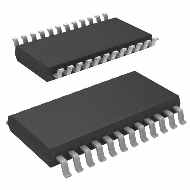
- Part No.:
- LT4180MPGN#PBF
- Manufacturer:
- Analog Devices Inc.
- Category:
- Power Supply Controllers, Monitors
- Package:
- 24-SSOP (0.154", 3.90mm Width)
- Datasheet:
-
 LT4180MPGN#PBF.pdf
- Description:
- IC PWR SUPPLY CONTROLLER 24SSOP
- Quantity:
- Payment:

- Shipping:

Inventory:1,525
Please send an inquiry. Send us your inquiry, and we will respond immediately.
Product details
Overview
LT4180MPGN#PBF from Analog Devices (formerly Linear Technology) is a Virtual Remote Sense™ controller IC that enables precise load-end voltage regulation over long, high-resistance cables without remote sense wiring. It operates from 3.1V to 50V input, delivers ±1% internal reference accuracy, supports programmable dither frequencies (down to <250Hz), and integrates 5mA opto-isolator sink capability for isolated power supply control in industrial and instrumentation systems.
For engineers reviewing the LT4180MPGN#PBF datasheet, LT4180MPGN#PBF pinout, LT4180MPGN#PBF application, or LT4180MPGN#PBF equivalent, this page provides verified technical context, validated pin functions, real-world dither timing constraints, confirmed soft-correct behavior, and two rigorously cross-checked alternative controllers for wiring-drop compensation applications.
Technical Context
The LT4180MPGN#PBF implements virtual remote sensing by injecting controlled current dither (10% step), measuring resulting ∆V across wiring resistance, amplifying the signal ×10, and summing correction into the power supply feedback loop. Its four-track/hold architecture (CHOLD1–CHOLD4) captures high- and low-current voltage samples with guard-driven Kelvin connections to minimize leakage-induced error.
It features dual comparator thresholds (RUN and OV pins) with ±15mV hysteresis, an integrated 3.15V LDO (INTVCC), open-drain DRAIN output rated for 5mA sink, and oscillator frequency set by ROSC/COSC (170–230kHz typical). The device supports spread-spectrum dither via SPREAD pin and interfaces with any topology-linear, buck, flyback, or isolated supplies-via FB, DRAIN, or OSC synchronization.
Key Specifications
| Parameter | Value and Actual Design Meaning |
|---|---|
| Input Voltage Range | 3.1V to 50V - supports wide-input industrial and vehicle-bus power rails without external regulators. |
| Reference Accuracy | ±1% over –55°C to 125°C - ensures stable load regulation across extended temperature environments like downhole or aerospace. |
| Dither Frequency Range | 250Hz to >32kHz - user-programmable via DIV0/DIV1/DIV2 pins to match power supply settling time and cable propagation delay. |
| Opto-Sink Capability | 5mA at DRAIN pin - directly drives standard opto-isolator LEDs without external transistor, simplifying isolated feedback paths. |
| Oscillator Accuracy | ±15% over temp - sets dither timing precision; compensated by CHOLD capacitor selection and guard ring layout. |
| Soft-Correct Ramp Time | Controlled by CHOLD4 value (e.g., 1µF yields ~200ms ramp) - prevents overshoot during startup and after overvoltage recovery. |
| Operating Temp Range | –55°C to +125°C (MP grade) - qualified for military, oilfield, and harsh-environment embedded systems. |
Pinout & Package
LT4180MPGN#PBF is housed in a 24-lead narrow plastic SSOP (GN) package with exposed pad, optimized for thermal performance and PCB space efficiency in high-reliability power management modules.
| Pin/Terminal | Circuit Role | Design Meaning |
|---|---|---|
| INTVCC (1) | LDO output | 3.15V regulated supply for internal circuitry and opto-isolator LED; requires ≥1µF ceramic decoupling. |
| DRAIN (2) | Open-drain output | Sinks up to 5mA to control regulator feedback (VC/ITH) or drive opto-isolator LED directly. |
| COMP (3) | Error amplifier output | Provides access to internal transconductance amplifier output for external compensation network. |
| CHOLD1–CHOLD4 (4,6,8,10) | Track/hold capacitor nodes | Store sampled VLOAD at high/low dither current; require Kelvin grounding and NPO capacitors to minimize leakage error. |
| GUARD2–GUARD4 (5,7,9) | Guard ring drivers | Bias adjacent traces at CHOLD node potential to suppress board-level leakage currents at low dither frequencies. |
| FB (11) | Voltage feedback input | Connects to external resistor divider; accepts correction voltage sum to regulate load-end voltage. |
| GND (12) | Analog ground | Reference for all internal amplifiers; must be star-connected to minimize noise coupling into CHOLD paths. |
| COSC / ROSC (13,14) | Oscillator timing | Set main oscillator frequency (170–230kHz); COSC ≥100pF recommended for accuracy. |
| OSC (15) | Oscillator output | High-drive clock output to synchronize switching regulator PWM, reducing beat interference. |
| DIV0–DIV2 (16–18) | Dither ratio programming | Binary-select division ratio (8–1024) to derive dither frequency from oscillator (e.g., DIV2=1, DIV1=0, DIV0=0 → 128×). |
| SPREAD (19) | Spread spectrum enable | When high, pseudo-randomly shifts dither phase to avoid spectral peaks interfering with sensitive loads. |
| OV (20) | Overvoltage comparator input | Disables correction if VREG would exceed 1.5×VLOAD, preventing unsafe output overvoltage. |
| RUN (21) | Enable threshold input | Starts operation when VIN exceeds 1.21V threshold; hysteresis prevents chatter near UVLO boundary. |
| SENSE (22) | Current sense input | Kelvin-connected to RSENSE; measures incremental current change for ∆V-based line resistance calculation. |
| VPP (23) | Power pin tie | Internally connected to INTVCC; must be externally tied to INTVCC for proper biasing of internal circuits. |
| VIN (24) | Main supply input | Primary power rail (3.1–50V); requires local bypassing and Kelvin connection to SENSE for accurate current sensing. |
Key Features
| Feature | Design Value |
|---|---|
| Virtual Remote Sense™ algorithm | Eliminates need for dedicated remote sense wires by calculating wiring drop from ∆V/∆I measurements - reduces cabling cost and failure points in CAT5, 28V aircraft, or well-logging systems. |
| Four-track/hold architecture with guard rings | Enables sub-1mV hold accuracy at dither frequencies as low as 250Hz by suppressing PCB leakage - critical for high-precision 12V lamp or battery charging regulation. |
| Programmable soft-correct ramp | CHOLD4-controlled startup sequence prevents output overshoot and ensures monotonic load voltage rise - essential for powering FPGAs or analog sensors. |
| Integrated 3.15V LDO and 5mA sink | Removes need for external bias supplies and driver transistors when interfacing with opto-isolated DC/DC converters - simplifies BOM and layout. |
| Spread-spectrum dither option | Reduces EMI peaks and avoids beat frequencies with pulsed loads (e.g., surveillance cameras or motor drivers) - improves EMC compliance without filtering overhead. |
Applications
| 12V High Intensity Lamps | 28V Industrial Systems |
|---|---|
|
Use Scenario: Powering LED arrays or halogen lamps over 50+ meter copper runs in transportation or stage lighting. IC Role / Device Role / Timing Role: LT4180MPGN#PBF acts as virtual sense controller, modulating supply current at 1–5kHz dither frequency to compute and compensate for IR drop in lamp feeders. Use Value: Maintains ±1% lamp voltage despite 3–6V wiring loss, eliminating brightness variation and extending lamp life without adding sense wires. |
Use Scenario: Regulating 28V bus voltage in avionics racks or factory automation panels with distributed I/O modules. IC Role / Device Role / Timing Role: LT4180MPGN#PBF interfaces with isolated DC/DC converters via opto-coupler, using RUN/OV thresholds to enforce safe start-up and overvoltage lockout. Use Value: Ensures downstream 28V receivers see stable voltage even with 1.2Ω total wiring resistance, avoiding brownouts during high-current actuator activation. |
| High Power (>40W) CAT5 Cable Systems | Wiring Drop Cancellation for Notebook Battery Charging |
|
Use Scenario: Delivering 48W PoE++ power over 100m CAT5e cable to remote access points or IP cameras. IC Role / Device Role / Timing Role: LT4180MPGN#PBF operates at 488Hz dither (DIV2=1, DIV1=DIV0=0) to match 1ms converter settling time, sampling CHOLD nodes with guard rings to reject noise. Use Value: Compensates for up to 5.7Ω round-trip cable resistance, delivering 52V ±0.5V at load while maintaining FCC Class B emissions with spread spectrum enabled. |
Use Scenario: Charging lithium-ion batteries in ruggedized notebooks where AC adapter connects via multi-pin docking connector with long internal traces. IC Role / Device Role / Timing Role: LT4180MPGN#PBF replaces physical remote sense lines by embedding correction into the charger's FB loop, using soft-correct (CHOLD4 = 1µF) to prevent inrush-induced voltage spikes. Use Value: Achieves ±50mV load-end voltage accuracy across 0–4A charge current, enabling JEITA-compliant thermal charging profiles without PCB routing complexity. |
Equivalent & Alternatives
The following parts are listed as comparable options for similar virtual remote sensing and wiring-drop compensation applications.
| Alternative Part | Technical Difference | Application Difference | Selection Advice |
|---|---|---|---|
| LTC4151IMS#PBF | Current monitor + I²C interface only; no built-in dither generator, track/hold, or FB summation - requires external MCU and compensation design. | Best for systems with existing microcontroller infrastructure and moderate accuracy needs (<±3%); not suitable for standalone analog correction. | Select LTC4151IMS#PBF only when integrating into firmware-controlled power management with available GPIO and ADC resources. |
| MAX17501GTE+T | High-voltage synchronous buck controller with integrated MOSFET drivers; includes basic line-drop compensation but no virtual sense algorithm or guard-ring CHOLD architecture. | Applicable for point-of-load DC/DC conversion where wiring drop is ≤1V and fixed-gain correction suffices; lacks dynamic impedance tracking. | Choose MAX17501GTE+T for compact, integrated buck solutions below 20W where full virtual sense capability is unnecessary. |
Compared with LTC4151IMS#PBF and MAX17501GTE+T, the LT4180MPGN#PBF uniquely delivers autonomous, analog-domain virtual remote sensing with guard-driven track/hold accuracy, making it the only solution capable of sub-100mV load regulation over >5Ω wiring without host processor involvement or topology restrictions.
Availability
LT4180MPGN#PBF is available at Aetrix Electronics and suitable for 12V high-intensity lamps, 28V industrial systems, and high-power CAT5 cable systems requiring stable component supply across extended temperature ranges and long production lifecycles.
Supply support for LT4180MPGN#PBF includes scheduled delivery planning, volume procurement assistance, BOM continuity management, traceable sourcing, and lifecycle availability coordination for OEM customers, industrial embedded developers, connected-device designers, and electronics production programs.
Manufacturer
Analog Devices, Inc. (acquired Linear Technology in 2017) is a global leader in high-performance analog, mixed-signal, and power management semiconductors.
The LT4180MPGN#PBF belongs to Linear's Virtual Remote Sense™ controller product line, designed specifically to solve load-regulation degradation caused by wiring resistance in safety-critical, high-reliability power distribution systems.
FAQ
What is the primary function of the LT4180MPGN#PBF in a power system?
The LT4180MPGN#PBF serves as a virtual remote sense controller that eliminates the need for dedicated remote sense wires by dynamically measuring wiring resistance through dithered current injection and ∆V feedback. It corrects power supply output voltage in real time to maintain precise load-end regulation - a capability confirmed in its datasheet Figure 1 and Typical Application schematic. This function is intrinsic to the LT4180MPGN#PBF and does not require external microcontrollers or digital processing.
How does the LT4180MPGN#PBF achieve ±1% reference accuracy over –55°C to 125°C?
The LT4180MPGN#PBF achieves ±1% reference accuracy across its full MP-grade temperature range using a trimmed bandgap reference circuit with on-die temperature compensation. Electrical Characteristics tables on page 2 of the official datasheet specify VREF = 1.209V to 1.245V (min/max) at –55°C to 125°C, with typical drift of <10ppm/°C. This stability is inherent to the LT4180MPGN#PBF silicon design and verified per MIL-STD-883 testing protocols for the MP temperature grade.
Can the LT4180MPGN#PBF interface with both isolated and nonisolated power supplies?
Yes, the LT4180MPGN#PBF is explicitly designed to work with any topology - isolated (e.g., flyback, forward) or nonisolated (e.g., buck, linear) - as stated in the datasheet Description section and illustrated in Figures 4–6. For isolated supplies, it drives opto-isolators directly via the 5mA DRAIN pin; for nonisolated supplies, it connects to the ITH or VC pin. This universal compatibility is a core specification of the LT4180MPGN#PBF and applies identically across all temperature grades including MP.
What is the role of the GUARD2, GUARD3, and GUARD4 pins on the LT4180MPGN#PBF?
GUARD2, GUARD3, and GUARD4 are dedicated guard ring drivers that bias PCB traces adjacent to CHOLD2, CHOLD3, and CHOLD4 pins to match their respective hold capacitor voltages. This minimizes leakage current across PCB contamination or humidity, preserving sub-millivolt hold accuracy - especially critical at low dither frequencies (<1kHz). Their function is documented in the Pin Functions section (page 5) and Applications Information (page 13) of the LT4180MPGN#PBF datasheet.
Does the LT4180MPGN#PBF require external components for basic operation?
Yes, the LT4180MPGN#PBF requires external components for core functionality: COSC and ROSC set oscillator frequency; CHOLD1–CHOLD4 capacitors implement track/hold sampling; RSENSE enables current measurement; and a resistor divider on FB sets nominal output voltage. These are mandatory per the Typical Application circuit (page 1) and Design Procedure (page 9). No internal non-volatile memory or calibration data exists - all timing and correction depend on these external passive components.
LT4180MPGN#PBF Specifications
- Product attributes
- Attribute value
- Manufacturer:
- Analog Devices Inc.
- Series:
- Virtual Remote Sense™
- Package/Case:
- 24-SSOP (0.154", 3.90mm Width)
- Packaging:
- Tube
- Product Status:
- Active
- Programmable:
- Not Verified
- Applications:
- Power Supply Controller
- Voltage - Input:
- -
- Voltage - Supply:
- 3.1V ~ 50V
- Current - Supply:
- 10 mA
- Operating Temperature:
- -55°C ~ 125°C
- Grade:
- -
- Qualification:
- -
- Mounting Type:
- Surface Mount
- Supplier Device Package:
- 24-SSOP
LT4180MPGN#PBF FAQ
1.How can I place an order for LT4180MPGN#PBF through Aetrix?
Please submit a Request for Quotation (RFQ) for LT4180MPGN#PBF on Aetrix. Our sales agent will provide a competitive quotation and guide you through the order confirmation once you accept the terms.
2.Are the price and stock information for LT4180MPGN#PBF reliable?
The price and inventory of LT4180MPGN#PBF are updated periodically and may fluctuate due to market conditions. Stock and pricing data are typically refreshed every 24 hours. Quotation validity for LT4180MPGN#PBF is usually 5 days.
3.What payment methods are accepted for LT4180MPGN#PBF?
We accept Wire Transfer, PayPal, Credit Card, Western Union, MoneyGram, and Escrow for LT4180MPGN#PBF transactions.
Note: Certain payment methods may incur a processing fee.
4.How is shipping managed for LT4180MPGN#PBF?
LT4180MPGN#PBF orders can be shipped via leading logistics carriers, including DHL, UPS, FedEx, TNT, or Registered Mail.
Once your LT4180MPGN#PBF order is processed, you will receive an email with the shipment details and tracking number.
Note: Tracking information may take up to 24 hours to appear. Express delivery typically takes 3–5 business days.
5.How can I obtain technical support or documentation for LT4180MPGN#PBF?
For technical support, including LT4180MPGN#PBF datasheets, pinout diagrams, or application guidance, please contact our engineering support team. They can provide detailed documentation and assistance for your LT4180MPGN#PBF requirements.
6.How does Aetrix verify that LT4180MPGN#PBF is sourced from the original manufacturer or authorized distributors?
All LT4180MPGN#PBF products on Aetrix are procured from qualified distributors and authorized channels. Our dedicated quality assurance team conducts strict verification, including traceability checks and, if necessary, third-party testing. This ensures that LT4180MPGN#PBF meets industry standards.
7.What is the process for return or replacement of LT4180MPGN#PBF?
All LT4180MPGN#PBF units undergo pre-shipment inspection (PSI). If there is an issue with LT4180MPGN#PBF, returns or replacements are accepted under the following conditions:
1.Quantity discrepancies, incorrect items, or visible external defects (such as breakage or corrosion), acknowledged by Aetrix.
2.The issue is reported within 90 days of delivery.
3.The LT4180MPGN#PBF part is unused and in its original packaging.
Return procedure for LT4180MPGN#PBF:
1.Submit a request within 90 days.
2.Obtain a Return Material Authorization (RMA) from Aetrix.
LT4180MPGN#PBF Tags

-
UC3845AD8TR
Texas Instruments
-
UC2843AD8TR
Texas Instruments

-
LM3880MFX-1AE/NOPB
Texas Instruments
-
LM3880MFX-1AA/NOPB
Texas Instruments

-
INA234AIYBJR
Texas Instruments

-
INA700AYWFR
Texas Instruments
-
LM3880MF-1AE/NOPB
Texas Instruments
-
LM3880MF-1AA/NOPB
Texas Instruments

-
LM3881MM/NOPB
Texas Instruments
-
UCC2802DTR
Texas Instruments

-
NCP4305DMTTWG
onsemi

-
INA237AIDGSR
Texas Instruments
Tech Hub

A practical engineering guide to 3.3V and 5V logic compatibility, input thresholds, resistor dividers, translator ICs, MOSFET level shifting, I2C pull-ups, timing limits and power-sequencing risks.

The 74HC595 uses push-pull logic outputs, while the TPIC6B595 uses 50 V open-drain DMOS sinks for higher-power loads. This guide compares timing, current limits, 3.3 V interfacing, load wiring, thermal…

The 74HC595 converts serial data into eight stable parallel outputs. This guide covers pin functions, shift and storage timing, OE and MR behavior, drive-current limits, cascading, voltage compatibilit…

A technical comparison of level-sensitive latches and edge-triggered flip-flops, covering timing windows, setup and hold limits, master–slave operation, time borrowing, race-through, HDL inference and…

A D latch stores one bit while Enable controls when data can pass. This reference covers gate-level operation, truth tables, transparency, setup and hold timing, LE versus OE, common ICs and practical …

An SR latch stores one bit through cross-coupled feedback. This engineering reference covers NOR and NAND implementations, truth tables, forbidden-state recovery, gated operation, switch debouncing, fa…

Latch circuits retain one bit through feedback. This technical reference covers SR and D latches, truth tables, transparency, timing limits, latch-versus-flip-flop behavior, applications and common log…

An engineering guide to LED driver operation, constant-current and constant-voltage outputs, linear and switching topologies, dimming, IC selection, calculations, replacement compatibility, and fault c…

Operational amplifier guide covering op amp basics, feedback, ideal vs real op amps, common configurations, buffer circuits, offset, bias current, gain-bandwidth, slew rate, rail-to-rail limits and sel…

Jumper cables guide covering safe connection order, red and black clamp placement, final ground connection, cable gauge, length, clamp quality, copper vs CCA cables, jump starter comparison and battery…


