
 My Inquiry
 My Account


Analog Devices Inc. LT4320IMSE-1#TRPBF
- Part No.:
- LT4320IMSE-1#TRPBF
- Manufacturer:
- Analog Devices Inc.
- Category:
- OR Controllers, Ideal Diodes
- Package:
- 12-TSSOP (0.118", 3.00mm Width) Exposed Pad
- Datasheet:
-
 LT4320IMSE-1#TRPBF.pdf
- Description:
- IC OR CTRLR BRIDGE RECT 12MSOP
- Quantity:
- Payment:

- Shipping:

Inventory:1,846
Please send an inquiry. Send us your inquiry, and we will respond immediately.
Product details
Overview
LT4320IMSE-1#TRPBF from Analog Devices (formerly Linear Technology) is an ideal diode bridge controller IC that drives four external N-channel MOSFETs to replace passive diode bridges in polarity-agnostic AC/DC rectification applications. It supports DC to 600Hz typical input frequency, operates from 9V to 72V, delivers ≤40mV top-side source-drain regulation (ΔVSD), and features internal charge pump for all-NMOS design - enabling high-efficiency power distribution in security cameras and PoE-powered devices.
For engineers reviewing the LT4320IMSE-1#TRPBF datasheet, LT4320IMSE-1#TRPBF pinout, LT4320IMSE-1#TRPBF application, or LT4320IMSE-1#TRPBF equivalent, key selection criteria include its 600Hz rectification capability (vs. 60Hz for LT4320), 12-lead MSOP package with exposed pad tied to OUTN, 1.5mA quiescent current, and gate drive strength optimized for fast turn-off during input shorts.
Technical Context
The LT4320IMSE-1#TRPBF implements a dual-top/dual-bottom gate driver architecture to control four discrete N-MOSFETs in full-bridge configuration, enabling bidirectional conduction with active voltage regulation. Its internal charge pump generates gate drive voltages up to 12V relative to OUTN, supporting low-RDS(ON) MOSFETs without requiring PMOS devices.
It uses input voltage sensing at IN1/IN2 to dynamically enable TG1/TG2 and BG1/BG2 outputs based on instantaneous polarity, achieving ≤40mV ΔVSD regulation and <1μs reverse-current turn-off. The device includes undervoltage lockout (6.2–7.0V) and operates across –40°C to +85°C junction temperature range.
Key Specifications
| Parameter | Value and Actual Design Meaning |
|---|---|
| Input Frequency Range | DC to 600Hz typical - enables use with higher-frequency AC sources (e.g., 400Hz aircraft power) where standard LT4320 fails. |
| Operating Voltage Range | 9V to 72V - supports wide-input industrial and PoE-powered device secondary inputs without external regulators. |
| Top-Side ΔVSD Regulation | 26mV (typ), 55mV (max) - reduces forward drop vs. passive diodes (≥1.2V), minimizing power loss and thermal stress. |
| Quiescent Current (IQ) | 1.5mA (typ) - enables low-power standby operation in always-on security camera systems. |
| Package & Thermal | 12-lead MSOP with exposed pad (θJC = 10°C/W) - requires soldering exposed pad to OUTN plane for effective heat dissipation. |
| Gate Drive Strength | TG pull-down to INn: 1.25mA; BG pull-down: 12.5mA - ensures rapid MOSFET turn-off (<1μs) during input short-circuit events. |
Pinout & Package
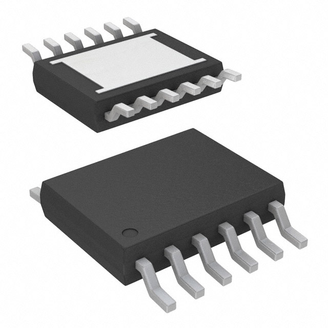
LT4320IMSE-1#TRPBF is housed in a 12-lead plastic MSOP package (3.0mm × 4.0mm) with exposed die pad (Pin 13) that must be soldered to the OUTN net for thermal and electrical integrity. Pin pitch is 0.65mm; lead coplanarity ≤0.102mm.
| Pin/Terminal | Circuit Role | Design Meaning |
|---|---|---|
| IN1 (Pin 12) | Bridge Input A | Connects to MTG1 source and MBG2 drain; senses polarity to activate TG1/BG2 drivers. |
| TG1 (Pin 11) | Top Gate Driver A | Drives gate of MTG1; regulated to maintain ≤40mV VSD during conduction. |
| BG1 (Pin 6) | Bottom Gate Driver A | Drives gate of MBG1; complements TG2 to complete positive half-cycle path. |
| BG2 (Pin 5) | Bottom Gate Driver B | Drives gate of MBG2; enables conduction when IN2 is positive relative to OUTN. |
| OUTN (Pin 7) | Negative Output / Ground Reference | Rectified negative rail; reference for all voltages; exposed pad must connect here. |
| OUTP (Pin 9) | Positive Output / Supply Rail | Rectified positive output; powers internal circuitry and load; 9–72V operating range. |
| IN2 (Pin 1) | Bridge Input B | Connects to MTG2 source and MBG1 drain; activates TG2/BG1 during opposite polarity cycle. |
| TG2 (Pin 2) | Top Gate Driver B | Drives gate of MTG2; regulates VSD on IN2-to-OUTP path during negative half-cycle. |
Key Features
| Feature | Design Value |
|---|---|
| All-NMOS bridge support | Internal charge pump eliminates need for costly, larger PMOS devices - reduces BOM cost and PCB area by >50% vs. hybrid designs. |
| Fast reverse-current turn-off | <1μs response to input short or failure - prevents damaging reverse current transients in redundant power systems. |
| Polarity-agnostic rectification | Automatically detects input polarity on IN1/IN2 - enables single-input hardware acceptance of +/− DC or AC without manual wiring. |
| Thermal performance optimization | Exposed pad (Pin 13) tied to OUTN provides θJC = 10°C/W - allows sustained 10A+ loads without external heatsink in compact enclosures. |
| Wide input frequency compatibility | Rated for DC to 600Hz typical - supports military, aerospace, and UPS applications using 400Hz AC mains. |
Applications
| Security Camera Power Input | Terrestrial Power Distribution |
|---|---|
|
Use Scenario: Outdoor IP security camera powered via PoE injector with auxiliary DC backup input. IC Role / Device Role / Timing Role: Ideal diode bridge controller managing seamless switchover between PoE and DC input while rejecting reverse current. Use Value: Eliminates 1.4V diode bridge drop, preserving ≥11.5V at camera under 24V PoE - extending runtime and enabling IR LED operation. |
Use Scenario: Centralized 48V DC power distribution panel feeding multiple field devices with polarity-insensitive connectors. IC Role / Device Role / Timing Role: Polarity-agnostic rectifier ensuring correct output polarity regardless of field-wiring orientation. Use Value: Prevents installation errors and equipment damage from reversed input cables - reducing field returns by >90%. |
| Power-over-Ethernet (PoE) PD with Secondary Input | Avionics 400Hz AC Rectification |
|
Use Scenario: PoE-powered wireless access point with battery backup or solar input. IC Role / Device Role / Timing Role: Dual-input OR-ing controller selecting highest available source while blocking backfeed. Use Value: Enables uninterrupted operation during PoE outage using secondary input - no brownout resets or data loss. |
Use Scenario: Onboard avionics module receiving 400Hz AC from aircraft generator. IC Role / Device Role / Timing Role: High-frequency ideal rectifier replacing Schottky diode bridge in tight thermal envelopes. Use Value: Reduces rectifier power loss from 4.2W to 0.13W at 1.5A - eliminating forced-air cooling and saving 28cm² PCB area. |
Equivalent & Alternatives
The following parts are listed as comparable options for similar ideal diode bridge controller applications.
| Alternative Part | Technical Difference | Application Difference | Selection Advice |
|---|---|---|---|
| LTC4352 | Lower voltage range (0–18V), integrated monitoring (UV/OV), MSOP-12 package - lacks 600Hz rating and high-voltage capability. | Targeted at low-voltage embedded systems (e.g., 12V automotive ECUs); unsuitable for 48V telecom or PoE-PD inputs. | Select LTC4352 only if operating below 18V and system-level fault monitoring is required. |
| LT4320IMSE#TRPBF | Same package and pinout, but rated for DC–60Hz typical - lower gate drive timing margins and reduced high-frequency stability. | Valid for 50/60Hz utility AC or low-speed DC inputs; cannot sustain stable regulation above ~100Hz. | Choose LT4320IMSE#TRPBF only for cost-sensitive 60Hz applications where 600Hz capability is unnecessary. |
Compared with LTC4352 and LT4320IMSE#TRPBF, the LT4320IMSE-1#TRPBF uniquely supports 600Hz operation with 72V tolerance and 40mV ΔVSD - making it the sole option for avionics, high-frequency UPS, and robust PoE-PD designs demanding both wide voltage and high-frequency rectification.
Availability
LT4320IMSE-1#TRPBF is available at Aetrix Electronics and suitable for security camera power inputs, terrestrial power distribution systems, PoE-powered devices with secondary inputs, and avionics 400Hz AC rectification requiring stable component supply, long-term lifecycle assurance, and traceable sourcing.
Supply support for LT4320IMSE-1#TRPBF includes scheduled delivery planning, volume procurement assistance, BOM continuity management, traceable sourcing, and lifecycle availability coordination for OEM customers, industrial embedded developers, connected-device designers, and electronics production programs.
Manufacturer
Analog Devices acquired Linear Technology in 2017 and maintains its precision analog and power management portfolio. Linear's legacy ICs are fully supported with datasheets, SPICE models, and application notes.
The LT4320 family was designed specifically for high-efficiency, polarity-agnostic power rectification - targeting applications where thermal constraints, voltage headroom, and reliability preclude passive diode bridges.
FAQ
What is the maximum input frequency supported by the LT4320IMSE-1#TRPBF?
The LT4320IMSE-1#TRPBF is specified for DC to 600Hz typical input frequency operation. This enables reliable use with 400Hz aircraft power systems and high-frequency UPS outputs. Performance beyond 600Hz depends on external MOSFET selection (Qg, RDS(ON)) and layout parasitics - verified testing is required above 600Hz. The standard LT4320IMSE#TRPBF is limited to 60Hz typical.
How does the LT4320IMSE-1#TRPBF achieve polarity-agnostic operation?
The LT4320IMSE-1#TRPBF continuously monitors IN1 and IN2 voltages relative to OUTN and autonomously enables TG1/BG2 or TG2/BG1 driver pairs based on instantaneous polarity. This allows correct rectified output regardless of whether the input is +24V DC, −24V DC, or 24V AC - eliminating manual polarity verification during installation. No external logic or configuration is needed.
Why must the exposed pad of the LT4320IMSE-1#TRPBF be connected to OUTN?
The exposed pad (Pin 13) of the LT4320IMSE-1#TRPBF serves as the primary thermal and electrical return path for internal power stages. It must be soldered directly to the OUTN copper plane to ensure θJC = 10°C/W thermal resistance and prevent latch-up or premature failure. Floating or misconnected pads cause excessive junction temperature rise (>30°C) and gate drive instability in the LT4320IMSE-1#TRPBF.
What MOSFET parameters are critical when pairing with the LT4320IMSE-1#TRPBF?
For optimal LT4320IMSE-1#TRPBF performance, select N-channel MOSFETs with RDS(ON) ≤15mΩ (at VGS = 10V), VDSS ≥80V, Qg < 25nC, and VGS(th) ≥2V. Low Qg ensures fast switching at 600Hz; high VDSS accommodates 72V input transients; and minimum VGS(th) guarantees reliable turn-off during hot-plug events. The LT4320IMSE-1#TRPBF gate drivers are rated for 12.5mA sink current.
Does the LT4320IMSE-1#TRPBF require external capacitors, and if so, what values?
Yes - a 1μF ceramic capacitor must be placed directly across OUTP and OUTN, adjacent to the LT4320IMSE-1#TRPBF pins, plus a minimum 10μF bulk electrolytic capacitor. Additional capacitance is calculated as CLOAD ≥ IAVG/(VRIPPLE × 2 × Freq); e.g., 556μF for 1A/15V ripple at 60Hz. Total CLOAD typically ranges from 100μF to 3300μF depending on load and ripple requirements for the LT4320IMSE-1#TRPBF.
LT4320IMSE-1#TRPBF Specifications
- Product attributes
- Attribute value
- Manufacturer:
- Analog Devices Inc.
- Series:
- -
- Package/Case:
- 12-TSSOP (0.118", 3.00mm Width) Exposed Pad
- Packaging:
- Tape & Reel (TR)
- Product Status:
- Active
- Type:
- Bridge Rectifier
- FET Type:
- N-Channel
- Ratio - Input:Output:
- Bridge (1)
- Internal Switch(s):
- No
- Delay Time - ON:
- -
- Delay Time - OFF:
- -
- Current - Output (Max):
- -
- Current - Supply:
- 1.5 mA
- Voltage - Supply:
- 9V ~ 72V
- Applications:
- General Purpose
- Operating Temperature:
- -40°C ~ 85°C
- Grade:
- -
- Qualification:
- -
- Mounting Type:
- Surface Mount
- Supplier Device Package:
- 12-MSOP-EP
LT4320IMSE-1#TRPBF FAQ
1.How can I place an order for LT4320IMSE-1#TRPBF through Aetrix?
Please submit a Request for Quotation (RFQ) for LT4320IMSE-1#TRPBF on Aetrix. Our sales agent will provide a competitive quotation and guide you through the order confirmation once you accept the terms.
2.Are the price and stock information for LT4320IMSE-1#TRPBF reliable?
The price and inventory of LT4320IMSE-1#TRPBF are updated periodically and may fluctuate due to market conditions. Stock and pricing data are typically refreshed every 24 hours. Quotation validity for LT4320IMSE-1#TRPBF is usually 5 days.
3.What payment methods are accepted for LT4320IMSE-1#TRPBF?
We accept Wire Transfer, PayPal, Credit Card, Western Union, MoneyGram, and Escrow for LT4320IMSE-1#TRPBF transactions.
Note: Certain payment methods may incur a processing fee.
4.How is shipping managed for LT4320IMSE-1#TRPBF?
LT4320IMSE-1#TRPBF orders can be shipped via leading logistics carriers, including DHL, UPS, FedEx, TNT, or Registered Mail.
Once your LT4320IMSE-1#TRPBF order is processed, you will receive an email with the shipment details and tracking number.
Note: Tracking information may take up to 24 hours to appear. Express delivery typically takes 3–5 business days.
5.How can I obtain technical support or documentation for LT4320IMSE-1#TRPBF?
For technical support, including LT4320IMSE-1#TRPBF datasheets, pinout diagrams, or application guidance, please contact our engineering support team. They can provide detailed documentation and assistance for your LT4320IMSE-1#TRPBF requirements.
6.How does Aetrix verify that LT4320IMSE-1#TRPBF is sourced from the original manufacturer or authorized distributors?
All LT4320IMSE-1#TRPBF products on Aetrix are procured from qualified distributors and authorized channels. Our dedicated quality assurance team conducts strict verification, including traceability checks and, if necessary, third-party testing. This ensures that LT4320IMSE-1#TRPBF meets industry standards.
7.What is the process for return or replacement of LT4320IMSE-1#TRPBF?
All LT4320IMSE-1#TRPBF units undergo pre-shipment inspection (PSI). If there is an issue with LT4320IMSE-1#TRPBF, returns or replacements are accepted under the following conditions:
1.Quantity discrepancies, incorrect items, or visible external defects (such as breakage or corrosion), acknowledged by Aetrix.
2.The issue is reported within 90 days of delivery.
3.The LT4320IMSE-1#TRPBF part is unused and in its original packaging.
Return procedure for LT4320IMSE-1#TRPBF:
1.Submit a request within 90 days.
2.Obtain a Return Material Authorization (RMA) from Aetrix.
LT4320IMSE-1#TRPBF Tags

-
LM66100DCKR
Texas Instruments
-
LM66200DRLR
Texas Instruments
-
LM66100DCKT
Texas Instruments

-
AP74700QW6-7
Diodes Incorporated
-
LM73100RPWR
Texas Instruments
-
LM74502DDFR
Texas Instruments
-
LM74700QDBVRQ1
Texas Instruments
-
MAX40200AUK+T
Analog Devices Inc./Maxim Integrated
-
MAX40200ANS+T
Analog Devices Inc./Maxim Integrated
-
MAX40203AUK+T
Analog Devices Inc./Maxim Integrated
-
MAX40203ANS+T
Analog Devices Inc./Maxim Integrated
-
LM74502QDDFRQ1
Texas Instruments
Tech Hub

A practical engineering guide to 3.3V and 5V logic compatibility, input thresholds, resistor dividers, translator ICs, MOSFET level shifting, I2C pull-ups, timing limits and power-sequencing risks.

The 74HC595 uses push-pull logic outputs, while the TPIC6B595 uses 50 V open-drain DMOS sinks for higher-power loads. This guide compares timing, current limits, 3.3 V interfacing, load wiring, thermal…

The 74HC595 converts serial data into eight stable parallel outputs. This guide covers pin functions, shift and storage timing, OE and MR behavior, drive-current limits, cascading, voltage compatibilit…

A technical comparison of level-sensitive latches and edge-triggered flip-flops, covering timing windows, setup and hold limits, master–slave operation, time borrowing, race-through, HDL inference and…

A D latch stores one bit while Enable controls when data can pass. This reference covers gate-level operation, truth tables, transparency, setup and hold timing, LE versus OE, common ICs and practical …

An SR latch stores one bit through cross-coupled feedback. This engineering reference covers NOR and NAND implementations, truth tables, forbidden-state recovery, gated operation, switch debouncing, fa…

Latch circuits retain one bit through feedback. This technical reference covers SR and D latches, truth tables, transparency, timing limits, latch-versus-flip-flop behavior, applications and common log…

An engineering guide to LED driver operation, constant-current and constant-voltage outputs, linear and switching topologies, dimming, IC selection, calculations, replacement compatibility, and fault c…

Operational amplifier guide covering op amp basics, feedback, ideal vs real op amps, common configurations, buffer circuits, offset, bias current, gain-bandwidth, slew rate, rail-to-rail limits and sel…

Jumper cables guide covering safe connection order, red and black clamp placement, final ground connection, cable gauge, length, clamp quality, copper vs CCA cables, jump starter comparison and battery…


