
 My Inquiry
 My Account


Analog Devices Inc. LT8316IFE#PBF
- Part No.:
- LT8316IFE#PBF
- Manufacturer:
- Analog Devices Inc.
- Category:
- DC DC Switching Controllers
- Package:
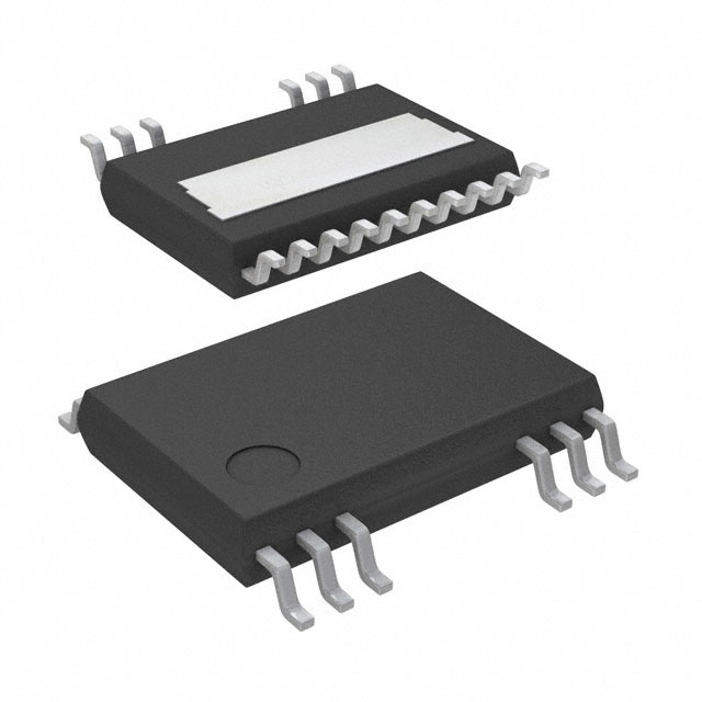
- 20-TSSOP (0.173", 4.40mm Width), 16 Leads, Exposed Pad
- Datasheet:
-
 LT8316IFE#PBF.pdf
- Description:
- 600VIN MICROPOWER, ISOLATED NO-O
- Quantity:
- Payment:

- Shipping:

Inventory:1,810
Please send an inquiry. Send us your inquiry, and we will respond immediately.
Product details
Overview
LT8316IFE#PBF from Analog Devices is a micropower, high-voltage isolated flyback controller enabling opto-isolator-free regulation via tertiary-winding voltage sampling. It operates from 16V to 560V input, delivers up to 4A output current at ≥160V input, and features quasi-resonant boundary-mode operation with 75μA quiescent current and 1.22V FB reference voltage. It is used in isolated housekeeping supplies for industrial inverters and EV battery stacks.
For engineers reviewing the LT8316IFE#PBF datasheet, LT8316IFE#PBF pinout, LT8316IFE#PBF application, or LT8316IFE#PBF equivalent, key selection considerations include its 560V VIN rating, no-opto isolation architecture, programmable constant-current/constant-voltage regulation, TSSOP-20(15) package with high-voltage creepage, and AEC-Q100-compliant temperature range (–40°C to 125°C).
Technical Context
The LT8316IFE#PBF implements boundary-mode (critical conduction mode) control using a DCM pin that detects negative dV/dt on a transformer tertiary winding to trigger precise zero-current sampling of the FB voltage. Its internal depletion-mode startup FET charges INTVCC without external components, and the VC pin governs both switching frequency and peak current limit via transconductance error amplification.
It integrates dual regulation loops: a voltage loop referencing 1.22V at FB and a current loop set by IREG/SS pin current (10μA), enabling seamless CV/CC transition. Temperature compensation is supported via TC pin (1.22V @ 25°C, +4.1mV/°C) to offset diode VF drift, and SMODE enables standby mode (220Hz min frequency) for ultralow-power operation.
Key Specifications
| Parameter | Value and Actual Design Meaning |
|---|---|
| Input Voltage Range | 16V to 560V continuous (600V transient); supports direct off-line and high-bus industrial inputs without pre-regulation. |
| Quiescent Current | 75μA in Burst Mode; enables <100mW no-load power consumption in isolated auxiliary supplies. |
| FB Regulation Voltage | 1.22V ±30mV over temperature; sets output accuracy baseline for resistor-divider programming of VOUT. |
| Switching Frequency Range | 3.5kHz–140kHz (boundary mode), down to 220Hz in Standby Mode; balances efficiency, EMI, and transformer size. |
| Current Sense Threshold | 20mV–110mV adjustable via RSNS; defines peak switch current and enables precise CC regulation. |
| Package | 20(15)-lead TSSOP with extended creepage; pins 1–3 are VIN (560V drain), exposed pad = GND; meets high-voltage spacing requirements. |
| Operating Temperature | –40°C to 125°C (I-grade); qualified for automotive and industrial environments with AEC-Q100 compliance exception. |
Pinout & Package
LT8316IFE#PBF uses a thermally enhanced 20(15)-lead plastic TSSOP package (FE grade) with extended creepage distance. Pins 1, 2, and 3 are internally connected VIN terminals rated for 560V continuous operation. The exposed pad (Pin 21) is GND and must be soldered to PCB ground for thermal management. Pin 15 and Pin 20 are dedicated GND connections; no internal connection exists for Pin 4–7 or Pin 11–14 in this variant.
| Pin/Terminal | Circuit Role | Design Meaning |
|---|---|---|
| VIN (1, 2, 3) | Drain of internal 560V depletion startup FET | Accepts high-voltage DC input; powers INTVCC during startup and enables direct connection to rectified AC lines. |
| INTVCC (8) | Internal gate driver bias supply | Regulated 10V LDO output; requires ≥2.2μF ceramic bypass capacitor for stable gate drive. |
| BIAS (9) | Unregulated IC power input | Derives operating power from transformer tertiary winding; reduces standby loss vs. resistive startup networks. |
| DCM (10) | Boundary mode detection input | Samples dV/dt of tertiary winding to trigger zero-current sampling; ensures accurate output voltage regulation. |
| FB (12) | Feedback input | Sampled voltage regulated to 1.22V; connects to resistor divider from tertiary winding to program VOUT. |
| IREG/SS (14) | Current regulation / soft-start | 10μA sink current sets CC threshold; RC network here provides programmable soft-start or current limit. |
| SMODE (16) | Standby mode enable | Tie to INTVCC to reduce min frequency to 220Hz; cuts no-load power for ultra-low-power applications. |
| SENSE (18) | Peak current sense input | Monitors MOSFET source voltage via RSNS; triggers current limit when voltage reaches 20–110mV window. |
| GATE (19) | External N-MOSFET driver output | High-speed gate driver (30ns rise/8ns fall); directly drives main power switch in flyback primary. |
| GND (15, 20) | Signal and power ground | Dual GND pins minimize ground bounce; exposed pad (Pin 21) must be soldered to PCB ground plane. |
Key Features
| Feature | Design Value |
|---|---|
| No-opto isolated regulation | Eliminates optocoupler, TL431, and associated compensation components-reducing BOM cost, board area, and aging-related drift. |
| Quasi-resonant boundary-mode control | Enables zero-current switching, improving efficiency >90% at full load and allowing smaller magnetics than CCM designs. |
| Programmable CV/CC regulation | Supports dual-loop output control: voltage regulation below current limit, automatic transition to constant-current mode above it. |
| Low-ripple Burst Mode® at light loads | Maintains tight output regulation (<±1%) down to 1% of full load while minimizing audible noise and EMI. |
| Integrated depletion-mode startup FET | Charges INTVCC capacitor directly from VIN-removes need for external bleeder resistors or startup windings. |
| Temperature-compensated feedback (TC pin) | PTAT voltage (+4.1mV/°C) offsets diode VF drift, enabling ±1% output stability across –40°C to 125°C without trimming. |
Applications
| Industrial Inverter Gate Drive Supply | EV Battery Stack Housekeeping Power |
|---|---|
|
Use Scenario: Isolated 12V/3A auxiliary supply powering gate drivers and sensors across 400–800V battery modules in electric vehicle traction inverters. IC Role / Device Role / Timing Role: Primary-side flyback controller regulating output from high-voltage DC bus without optocouplers; samples tertiary winding to close voltage loop. Use Value: Enables compact, reliable, and AEC-Q100-aligned auxiliary power with <100mW no-load consumption and immunity to optocoupler aging. |
Use Scenario: Off-line 24V/2A isolated supply for monitoring electronics in multi-cell lithium-ion battery packs operating up to 1000V total stack voltage. IC Role / Device Role / Timing Role: High-input-voltage flyback controller delivering regulated output using transformer-coupled sensing; supports wide VIN range and low quiescent current. Use Value: Provides robust, maintenance-free housekeeping power with built-in UVLO, thermal protection, and CV/CC flexibility for diverse sensor and MCU loads. |
| Medical Equipment Isolated Auxiliary Supply | Telecom Off-Line Management Power |
|
Use Scenario: 5V/1A isolated supply for microcontrollers and communication interfaces in Class II medical devices requiring reinforced insulation and low leakage. IC Role / Device Role / Timing Role: No-opto flyback controller implementing boundary-mode switching with precise FB sampling to meet IEC 60601 creepage and EMI limits. Use Value: Achieves >85% efficiency at full load and <75μA quiescent current-meeting stringent energy efficiency and safety standards without optocoupler certification overhead. |
Use Scenario: 3.3V/500mA isolated standby supply for baseband processors and PMICs in 48V telecom systems, operating continuously during sleep mode. IC Role / Device Role / Timing Role: High-voltage flyback controller with SMODE-enabled 220Hz standby mode, reducing no-load power to <30mW. Use Value: Delivers certified isolation and ultra-low standby consumption while supporting hot-swap and brownout recovery via EN/UVLO hysteresis. |
Equivalent & Alternatives
The following parts are listed as comparable options for similar high-voltage isolated flyback controller applications.
| Alternative Part | Technical Difference | Application Difference | Selection Advice |
|---|---|---|---|
| LT3748EMSE#PBF | Requires optocoupler feedback; lacks integrated TC compensation and SMODE standby mode; 105V max VIN. | Better suited for lower-input-voltage telecom supplies where opto-based regulation is acceptable and tighter output tolerance is needed. | Choose LT3748EMSE#PBF only if optocoupler integration is preferred and input voltage remains ≤105V. |
| UCC28740DR | 650V max VIN but no integrated depletion startup FET; higher 300μA quiescent current; no TC pin or CV/CC dual-loop capability. | Targeted at cost-sensitive consumer adapters; lacks AEC-Q100 qualification and temperature-compensated regulation. | Select UCC28740DR for non-automotive, non-medical applications where startup simplicity and lowest BOM cost outweigh precision and reliability needs. |
Compared with LT3748EMSE#PBF and UCC28740DR, the LT8316IFE#PBF uniquely combines 560V operation, no-opto regulation, TC-based diode compensation, and AEC-Q100 alignment-making it the only choice for high-reliability, high-input-voltage isolated supplies demanding long-term stability without optocoupler degradation.
Availability
LT8316IFE#PBF is available at Aetrix Electronics and suitable for industrial inverter gate drive supplies, EV battery stack housekeeping, and medical isolated auxiliary power requiring stable component supply, long-lifecycle support, and AEC-Q100-aligned qualification.
Supply support for LT8316IFE#PBF includes scheduled delivery planning, volume procurement assistance, BOM continuity management, traceable sourcing, and lifecycle availability coordination for OEM customers, industrial embedded developers, connected-device designers, and electronics production programs.
Manufacturer
Analog Devices, Inc. is a global leader in high-performance analog, mixed-signal, and digital signal processing semiconductors, serving industrial, automotive, communications, and healthcare markets since 1965.
The LT8316IFE#PBF belongs to Analog Devices' Power by Linear™ isolated controller product line, designed specifically for high-voltage, no-opto flyback topologies in space-constrained, safety-critical applications such as EV subsystems and medical equipment.
FAQ
What is the maximum continuous input voltage rating for the LT8316IFE#PBF?
The LT8316IFE#PBF has a maximum continuous input voltage rating of 560V at the VIN pins (1, 2, 3), with transient capability up to 600V. This rating is validated per Absolute Maximum Ratings and applies across the full –40°C to 125°C operating junction temperature range. Exceeding 560V continuously may degrade long-term reliability, and layout must maintain ≥8mm creepage between VIN and low-voltage pins per the FE package specification.
How does the LT8316IFE#PBF achieve regulation without an optocoupler?
The LT8316IFE#PBF achieves opto-isolator-free regulation by sampling the flyback pulse voltage from a dedicated tertiary winding on the transformer via the FB pin. During boundary-mode operation, the IC triggers sampling when secondary current reaches zero-eliminating parasitic resistance errors-and compares the sampled voltage to its internal 1.22V reference. This method replaces optocoupler feedback while maintaining ±1% output accuracy across line, load, and temperature.
Can the LT8316IFE#PBF support both constant-voltage and constant-current output modes?
Yes, the LT8316IFE#PBF supports dual-loop CV/CC regulation. The FB pin regulates output voltage to 1.22V, while the IREG/SS pin-sinking a precise 10μA current-sets the constant-current threshold. When load demand exceeds the programmed current limit, the IC automatically transitions from CV to CC mode, maintaining stable current delivery without external circuitry. This is confirmed in the Applications Information section and typical performance graphs.
What is the purpose of the TC pin on the LT8316IFE#PBF, and how is it used?
The TC pin on the LT8316IFE#PBF provides a buffered proportional-to-absolute-temperature (PTAT) voltage (1.22V at 25°C, +4.1mV/°C) to compensate for the negative temperature coefficient of the output rectifier diode. By connecting a resistor (RTC) from TC to FB, the IC counteracts diode VF drift-reducing output voltage variation from ±400mV to <±1% across –40°C to 125°C. RTC value is calculated using the measured diode TCF and transformer turns ratio.
Is the LT8316IFE#PBF pin-compatible with other variants like LT8316EFE#PBF or LT8316HFE#PBF?
Yes, the LT8316IFE#PBF is pin-compatible with LT8316EFE#PBF and LT8316HFE#PBF-all use the same 20(15)-lead TSSOP (FE) package and identical pinout. The only differences are operating temperature grade (I-grade: –40°C to 125°C; E-grade: 0°C to 125°C; H-grade: –40°C to 150°C) and associated electrical characterization. PCB layout and schematic design can be reused across these variants without modification.
LT8316IFE#PBF Specifications
- Product attributes
- Attribute value
- Manufacturer:
- Analog Devices Inc.
- Series:
- -
- Package/Case:
- 20-TSSOP (0.173", 4.40mm Width), 16 Leads, Exposed Pad
- Packaging:
- Tube
- Product Status:
- Active
- Output Type:
- Transistor Driver
- Function:
- Step-Up, Step-Down
- Output Configuration:
- Positive
- Topology:
- Buck, Boost, Flyback
- Number of Outputs:
- 1
- Output Phases:
- 1
- Voltage - Supply (Vcc/Vdd):
- 16V ~ 600V
- Frequency - Switching:
- 220Hz ~ 140kHz
- Duty Cycle (Max):
- -
- Synchronous Rectifier:
- Yes
- Clock Sync:
- -
- Serial Interfaces:
- -
- Control Features:
- Current Limit, Enable, Soft Start
- Operating Temperature:
- -40°C ~ 125°C (TJ)
- Grade:
- -
- Qualification:
- -
- Mounting Type:
- Surface Mount
- Supplier Device Package:
- 20-TSSOP-EP
LT8316IFE#PBF FAQ
1.How can I place an order for LT8316IFE#PBF through Aetrix?
Please submit a Request for Quotation (RFQ) for LT8316IFE#PBF on Aetrix. Our sales agent will provide a competitive quotation and guide you through the order confirmation once you accept the terms.
2.Are the price and stock information for LT8316IFE#PBF reliable?
The price and inventory of LT8316IFE#PBF are updated periodically and may fluctuate due to market conditions. Stock and pricing data are typically refreshed every 24 hours. Quotation validity for LT8316IFE#PBF is usually 5 days.
3.What payment methods are accepted for LT8316IFE#PBF?
We accept Wire Transfer, PayPal, Credit Card, Western Union, MoneyGram, and Escrow for LT8316IFE#PBF transactions.
Note: Certain payment methods may incur a processing fee.
4.How is shipping managed for LT8316IFE#PBF?
LT8316IFE#PBF orders can be shipped via leading logistics carriers, including DHL, UPS, FedEx, TNT, or Registered Mail.
Once your LT8316IFE#PBF order is processed, you will receive an email with the shipment details and tracking number.
Note: Tracking information may take up to 24 hours to appear. Express delivery typically takes 3–5 business days.
5.How can I obtain technical support or documentation for LT8316IFE#PBF?
For technical support, including LT8316IFE#PBF datasheets, pinout diagrams, or application guidance, please contact our engineering support team. They can provide detailed documentation and assistance for your LT8316IFE#PBF requirements.
6.How does Aetrix verify that LT8316IFE#PBF is sourced from the original manufacturer or authorized distributors?
All LT8316IFE#PBF products on Aetrix are procured from qualified distributors and authorized channels. Our dedicated quality assurance team conducts strict verification, including traceability checks and, if necessary, third-party testing. This ensures that LT8316IFE#PBF meets industry standards.
7.What is the process for return or replacement of LT8316IFE#PBF?
All LT8316IFE#PBF units undergo pre-shipment inspection (PSI). If there is an issue with LT8316IFE#PBF, returns or replacements are accepted under the following conditions:
1.Quantity discrepancies, incorrect items, or visible external defects (such as breakage or corrosion), acknowledged by Aetrix.
2.The issue is reported within 90 days of delivery.
3.The LT8316IFE#PBF part is unused and in its original packaging.
Return procedure for LT8316IFE#PBF:
1.Submit a request within 90 days.
2.Obtain a Return Material Authorization (RMA) from Aetrix.
LT8316IFE#PBF Tags

-
UCC28C45DR
Texas Instruments
-
UCC28C40DR
Texas Instruments
-
UCC28C43DR
Texas Instruments

-
ZXSC410E6TA
Diodes Incorporated

-
LM3524DMX/NOPB
Texas Instruments

-
LM3489MMX/NOPB
Texas Instruments
-
MIC2102YML-TR
Microchip Technology

-
LM5148RGYR
Texas Instruments
-
TL598CDR
Texas Instruments

-
LM5155DSSR
Texas Instruments

-
LM25085MYX/NOPB
Texas Instruments
-
UCC2813DTR-0
Texas Instruments
Tech Hub

A practical engineering guide to 3.3V and 5V logic compatibility, input thresholds, resistor dividers, translator ICs, MOSFET level shifting, I2C pull-ups, timing limits and power-sequencing risks.

The 74HC595 uses push-pull logic outputs, while the TPIC6B595 uses 50 V open-drain DMOS sinks for higher-power loads. This guide compares timing, current limits, 3.3 V interfacing, load wiring, thermal…

The 74HC595 converts serial data into eight stable parallel outputs. This guide covers pin functions, shift and storage timing, OE and MR behavior, drive-current limits, cascading, voltage compatibilit…

A technical comparison of level-sensitive latches and edge-triggered flip-flops, covering timing windows, setup and hold limits, master–slave operation, time borrowing, race-through, HDL inference and…

A D latch stores one bit while Enable controls when data can pass. This reference covers gate-level operation, truth tables, transparency, setup and hold timing, LE versus OE, common ICs and practical …

An SR latch stores one bit through cross-coupled feedback. This engineering reference covers NOR and NAND implementations, truth tables, forbidden-state recovery, gated operation, switch debouncing, fa…

Latch circuits retain one bit through feedback. This technical reference covers SR and D latches, truth tables, transparency, timing limits, latch-versus-flip-flop behavior, applications and common log…

An engineering guide to LED driver operation, constant-current and constant-voltage outputs, linear and switching topologies, dimming, IC selection, calculations, replacement compatibility, and fault c…

Operational amplifier guide covering op amp basics, feedback, ideal vs real op amps, common configurations, buffer circuits, offset, bias current, gain-bandwidth, slew rate, rail-to-rail limits and sel…

Jumper cables guide covering safe connection order, red and black clamp placement, final ground connection, cable gauge, length, clamp quality, copper vs CCA cables, jump starter comparison and battery…


