
 My Inquiry
 My Account


Analog Devices Inc. LT8500EUHH#TRPBF
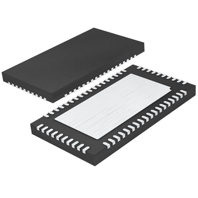
- Part No.:
- LT8500EUHH#TRPBF
- Manufacturer:
- Analog Devices Inc.
- Category:
- LED Drivers
- Package:
- 56-WFQFN Exposed Pad
- Datasheet:
-
 LT8500EUHH#TRPBF.pdf
- Description:
- IC PWM GENERATOR 56-QFN
- Quantity:
- Payment:

- Shipping:

Inventory:4,550
Please send an inquiry. Send us your inquiry, and we will respond immediately.
Product details
Overview
LT8500EUHH#TRPBF from Analog Devices is a 48-channel, 12-bit PWM generator IC designed for high-precision LED backlighting and display control. It delivers independent 4096-step PWM width resolution per channel, supports 50MHz cascadable serial interface, and enables 120° phase-shifted operation across three 16-channel banks - all in a 56-pin 6mm × 6mm TLA QFN package rated for –40°C to 125°C junction temperature.
For engineers reviewing the LT8500EUHH#TRPBF datasheet, LT8500EUHH#TRPBF pinout, LT8500EUHH#TRPBF application, or LT8500EUHH#TRPBF equivalent, this page provides verified technical context, real-world timing behavior, diagnostic flag handling (SYNC ERROR/OPENLED), cascaded topology constraints, and design-meaningful specifications - all grounded in the official Rev C datasheet and Analog Devices' validated electrical characteristics.
Technical Context
The LT8500EUHH#TRPBF implements a fully buffered 5-wire serial interface (SDI/SCKI/LDIBLANK/SDO/SCKO) with internal skew balancing and 50MHz SCKI support, enabling frame rates up to 85.5kHz. Its PWM generation relies on a free-running 25MHz PWMCK counter synchronized to LDIBLANK edges, with each of the 48 outputs driven by a dedicated 12-bit PWMRSYNC register updated via command frames.
It integrates dual-function LDIBLANK (latch data input + global blank/reset), on-die 100kΩ OPENLED pull-up, and a correction multiplier that scales incoming 12-bit channel data using programmable 6-bit ±50% correction registers. Diagnostic status - including synchronization error (SYC), open LED fault flags (NOL[48:1]), and phase-shift state (PHS) - is returned in every status frame via SDO.
Key Specifications
| Parameter | Value and Actual Design Meaning |
|---|---|
| Channels | 48 independent PWM outputs, grouped into three 16-channel banks for phase-shifted operation |
| PWM resolution | 12-bit (4096 steps) per channel - enables fine-grained brightness control in LED displays |
| PWM frequency | Up to 6.1kHz at 25MHz PWMCK - matches dynamic backlighting refresh requirements |
| Serial interface | 50MHz TTL/CMOS SCKI with 584-bit frame (48×12-bit PWM + 48×6-bit COR + 8-bit CMD) |
| Correction range | 6-bit (64 steps), ±50% of programmed PWM width - compensates for LED binning or driver mismatch |
| Operating voltage | 3.0V to 5.5V VCC - compatible with standard 3.3V and 5V logic domains |
| Package | 56-pin TLA QFN (6mm × 6mm × 0.78mm), exposed pad (Pin 57) = GND - supports high-density PCB layout |
Pinout & Package
LT8500EUHH#TRPBF uses a 56-lead plastic TLA QFN package (6mm × 6mm, 0.78mm height) with exposed thermal pad (Pin 57 = GND). The package is lead-free and tape-and-reel compatible (#TRPBF suffix).
| Pin/Terminal | Circuit Role | Design Meaning |
|---|---|---|
| PWM[48:1] | PWM output drivers | 48 open-drain CMOS outputs; VOH ≥ 4.0V @ 3mA (VCC = 5V), VOL ≤ 1.0V @ 3mA - directly drive LED anodes or LT3595A inputs |
| SCKI (B12) | Serial clock input | 50MHz max input clock; controls shift register timing and correction multiplier calculation - independent of PWMCK |
| SDI (B14) | Serial data input | Accepts 584-bit command frames (MSB-first); latched on rising SCKI edges - no external framing required |
| LDIBLANK (A28) | Dual-function control input | Rising edge ends frame and executes CMD; >50µs high asserts BLANK (resets all PWMs) - requires precise pulse-width control |
| SDO (A25) | Serial data output | Returns status frame (COR registers, SYC/OLT/PHS flags, NOL[48:1]) synchronously with SCKO - enables daisy-chain readback |
| SCKO (B13) | Serial clock output | Buffered, skew-balanced replica of SCKI - drives next device's SCKI in 5-wire cascade - tDC-SCK ≤ ±0.2ns |
| OPENLED (B11) | Diagnostic status input | Wired-OR open-collector input with 100kΩ internal pull-up; captures LED string fault state per PWMCK edge - used with LT3595A for fault localization |
| PWMCK (A27) | PWM timing clock input | 25MHz max clock source for PWM counter; determines PWM period (4096 cycles = 164µs @ 25MHz) - independent of serial interface clock |
| VCC (A26) | Power supply | 3.0V–5.5V analog/digital rail; requires local 0.1µF bypass capacitor - powers all logic and output drivers |
| GND (Pin 57) | Ground reference | Exposed thermal pad; must be soldered to PCB ground plane - critical for thermal performance (θJC = 5°C/W) |
Key Features
| Feature | Design Value |
|---|---|
| 48-channel phase-shifted PWM | Three 16-channel banks configurable for 120° inter-bank offset - reduces peak current and EMI in large-area LED backlights |
| Cascadable 5-wire interface | Integrated SCKO/SDO skew balancing enables >10-device chains at 50MHz without external buffers - simplifies high-channel-count PCB routing |
| Real-time diagnostic flags | SYNC ERROR (SYC) and OPEN LED (NOL[48:1]) reported in every status frame - enables closed-loop fault detection without host polling overhead |
| Per-channel correction multiplier | 6-bit ±50% correction applied digitally before PWMRSYNC load - compensates for LED forward-voltage variation across panels without firmware intervention |
| Self-test diagnostic mode | Command-triggered OPENLED self-test (CMD = 0x5X) pulses each PWM channel individually - identifies open-circuit LED strings down to individual channel level |
Applications
| Large-Screen LCD Backlighting | Mono-/Full-Color LED Displays |
|---|---|
|
Use Scenario: Dynamic local dimming in 55"+ commercial LCD TVs and digital signage, where brightness must adapt per zone in real time. IC Role / Device Role / Timing Role: Primary PWM controller generating synchronized, phase-shifted 48-channel outputs to drive multiple LT3595A LED drivers. Use Value: Enables 6.1kHz PWM frequency with <50ns propagation delay matching (tPD-PWM = 32–50ns), eliminating visible flicker while supporting fast video frame updates. |
Use Scenario: High-fidelity color mixing in RGB LED video walls, requiring independent intensity control of red, green, and blue subpixels. IC Role / Device Role / Timing Role: Centralized 12-bit PWM generator coordinating 48 channels across three color groups with matched rise/fall times (tR/tF = 12ns). Use Value: 4096-step resolution ensures smooth grayscale transitions; 6-bit correction registers compensate for binning-induced luminance variance between LED lots. |
| LED Billboards & Signboards | Industrial Control & ATE |
|
Use Scenario: Outdoor advertising displays operating under wide temperature (-40°C to 125°C) and high ambient light conditions. IC Role / Device Role / Timing Role: Robust PWM engine with built-in OPENLED fault detection and SYNC ERROR monitoring for unattended operation. Use Value: On-chip 100kΩ OPENLED pull-up and status-frame reporting enable autonomous open-string detection - reducing field service calls by identifying failed zones remotely. |
Use Scenario: Precision intensity control in automated test equipment for optical sensor calibration and LED characterization benches. IC Role / Device Role / Timing Role: Programmable 48-channel waveform generator with deterministic 584-bit frame timing (11.7µs/frame @ 50MHz SCKI). Use Value: Sub-microsecond timing accuracy (tSU-SDI = 3ns, tHD-SDI = 1.75ns) ensures repeatable stimulus delivery - critical for parametric testing of photodiodes and spectrometers. |
Equivalent & Alternatives
The following parts are listed as comparable options for similar 48-channel PWM generator applications.
| Alternative Part | Technical Difference | Application Difference | Selection Advice |
|---|---|---|---|
| TLC5947IPWPR | 24-channel, 12-bit PWM; 30MHz SPI interface; no phase-shift or OPENLED diagnostics | Limited to smaller displays; lacks cascading support and real-time fault reporting | Choose for cost-sensitive, lower-channel-count designs where diagnostic features are non-critical |
| IS31FL3731-QFLS4-TR | 28-channel, 8-bit PWM; I²C interface; integrated current regulation; no serial cascade capability | Targets compact RGB matrix displays; not suitable for high-power backlighting or multi-chip systems | Prefer when board space is constrained and constant-current LED driving is required over voltage-mode PWM |
Compared with TLC5947IPWPR and IS31FL3731-QFLS4-TR, the LT8500EUHH#TRPBF uniquely combines 48-channel count, 50MHz cascadable interface, per-channel correction, and hardware-level OPENLED/SYNC diagnostics - making it the only option qualified for industrial-grade, large-area LED backlighting with zero-touch fault management.
Availability
LT8500EUHH#TRPBF is available at Aetrix Electronics and suitable for large-screen LCD backlighting, mono-/full-color LED displays, LED billboards and signboards, industrial control systems, and automated test equipment requiring stable component supply across extended temperature ranges.
Supply support for LT8500EUHH#TRPBF includes scheduled delivery planning, volume procurement assistance, BOM continuity management, traceable sourcing, and lifecycle availability coordination for OEM customers, industrial embedded developers, connected-device designers, and electronics production programs.
Manufacturer
Analog Devices, Inc. (ADI) is a global leader in high-performance analog, mixed-signal, and digital signal processing semiconductors, serving industrial, automotive, communications, and healthcare markets.
The LT8500EUHH#TRPBF belongs to ADI's LED lighting control product line, engineered specifically for high-channel-count, high-speed, diagnostic-capable PWM generation in demanding display and signage applications - emphasizing timing precision, thermal robustness, and system-level fault visibility.
FAQ
What is the maximum PWM frequency supported by the LT8500EUHH#TRPBF?
The LT8500EUHH#TRPBF achieves up to 6.1kHz PWM frequency when driven by a 25MHz PWMCK clock (4096-cycle period). This is confirmed in the datasheet's Timing Characteristics table (fPWMCK = 25MHz, tPD-PWM = 32–50ns). The LT8500EUHH#TRPBF does not support higher PWM frequencies without external clock division or frame-rate reduction.
How does the LT8500EUHH#TRPBF handle open LED fault detection?
The LT8500EUHH#TRPBF monitors the OPENLED pin (B11) - an open-collector input with internal 100kΩ pull-up - and reports its state in every status frame. During self-test mode (CMD = 0x5X), it sequentially pulses each PWM channel and captures OPENLED state per channel, returning 48 individual NOL[48:1] flags. This enables precise fault localization when paired with LT3595A drivers.
Can the LT8500EUHH#TRPBF be cascaded with other LT8500 devices?
Yes, the LT8500EUHH#TRPBF supports daisy-chain cascading via its 5-wire interface (SDI/SCKI/LDIBLANK/SDO/SCKO). SCKO provides a skew-balanced clock replica to drive the next device's SCKI, enabling >10-device chains at 50MHz. The datasheet confirms this topology eliminates global clock routing and reduces buffer requirements versus conventional 4-wire schemes.
What is the function of the LDIBLANK pin on the LT8500EUHH#TRPBF?
The LDIBLANK pin (A28) serves two roles: LDI (latch data input) and BLANK (global reset). A rising edge always terminates the current command frame and executes the CMD field. Holding LDIBLANK high >50µs asserts BLANK - turning off all PWM outputs and resetting internal registers. The LT8500EUHH#TRPBF requires strict pulse-width control: <5µs for safe LDI-only operation.
Does the LT8500EUHH#TRPBF require external components for basic operation?
Yes, the LT8500EUHH#TRPBF requires a 0.1µF ceramic capacitor between VCC (A26) and GND (Pin 57) for power supply decoupling. No external pull-ups are needed on SDI, SCKI, or LDIBLANK - all are CMOS-compatible with rail-to-rail thresholds. The OPENLED pin includes an internal 100kΩ pull-up, eliminating the need for an external resistor in standard configurations.
LT8500EUHH#TRPBF Specifications
- Product attributes
- Attribute value
- Manufacturer:
- Analog Devices Inc.
- Series:
- -
- Package/Case:
- 56-WFQFN Exposed Pad
- Packaging:
- Tape & Reel (TR)
- Product Status:
- Obsolete
- Type:
- PWM Generator
- Topology:
- -
- Internal Switch(s):
- -
- Number of Outputs:
- -
- Voltage - Supply (Min):
- -
- Voltage - Supply (Max):
- -
- Voltage - Output:
- -
- Current - Output / Channel:
- -
- Frequency:
- -
- Dimming:
- -
- Applications:
- -
- Operating Temperature:
- -40°C ~ 125°C
- Grade:
- -
- Qualification:
- -
- Mounting Type:
- Surface Mount
- Supplier Device Package:
- 56-QFN (5x9)
LT8500EUHH#TRPBF FAQ
1.How can I place an order for LT8500EUHH#TRPBF through Aetrix?
Please submit a Request for Quotation (RFQ) for LT8500EUHH#TRPBF on Aetrix. Our sales agent will provide a competitive quotation and guide you through the order confirmation once you accept the terms.
2.Are the price and stock information for LT8500EUHH#TRPBF reliable?
The price and inventory of LT8500EUHH#TRPBF are updated periodically and may fluctuate due to market conditions. Stock and pricing data are typically refreshed every 24 hours. Quotation validity for LT8500EUHH#TRPBF is usually 5 days.
3.What payment methods are accepted for LT8500EUHH#TRPBF?
We accept Wire Transfer, PayPal, Credit Card, Western Union, MoneyGram, and Escrow for LT8500EUHH#TRPBF transactions.
Note: Certain payment methods may incur a processing fee.
4.How is shipping managed for LT8500EUHH#TRPBF?
LT8500EUHH#TRPBF orders can be shipped via leading logistics carriers, including DHL, UPS, FedEx, TNT, or Registered Mail.
Once your LT8500EUHH#TRPBF order is processed, you will receive an email with the shipment details and tracking number.
Note: Tracking information may take up to 24 hours to appear. Express delivery typically takes 3–5 business days.
5.How can I obtain technical support or documentation for LT8500EUHH#TRPBF?
For technical support, including LT8500EUHH#TRPBF datasheets, pinout diagrams, or application guidance, please contact our engineering support team. They can provide detailed documentation and assistance for your LT8500EUHH#TRPBF requirements.
6.How does Aetrix verify that LT8500EUHH#TRPBF is sourced from the original manufacturer or authorized distributors?
All LT8500EUHH#TRPBF products on Aetrix are procured from qualified distributors and authorized channels. Our dedicated quality assurance team conducts strict verification, including traceability checks and, if necessary, third-party testing. This ensures that LT8500EUHH#TRPBF meets industry standards.
7.What is the process for return or replacement of LT8500EUHH#TRPBF?
All LT8500EUHH#TRPBF units undergo pre-shipment inspection (PSI). If there is an issue with LT8500EUHH#TRPBF, returns or replacements are accepted under the following conditions:
1.Quantity discrepancies, incorrect items, or visible external defects (such as breakage or corrosion), acknowledged by Aetrix.
2.The issue is reported within 90 days of delivery.
3.The LT8500EUHH#TRPBF part is unused and in its original packaging.
Return procedure for LT8500EUHH#TRPBF:
1.Submit a request within 90 days.
2.Obtain a Return Material Authorization (RMA) from Aetrix.
LT8500EUHH#TRPBF Tags

-
BCR402RE6327HTSA1
Infineon Technologies

-
BCR430UXTSA2
Infineon Technologies

-
BCR420UE6433HTMA1
Infineon Technologies
-
BCR420UE6327HTSA1
Infineon Technologies
-
BCR421UE6327HTSA1
Infineon Technologies

-
LYT1604D-TL
Power Integrations

-
HV9910CLG-G
Microchip Technology

-
CL2N8-G
Microchip Technology

-
BCR420UW6-7
Diodes Incorporated
-
BCR421UW6-7
Diodes Incorporated

-
BCR420UFD-7
Diodes Incorporated
-
BCR421UFD-7
Diodes Incorporated
Tech Hub

A practical engineering guide to 3.3V and 5V logic compatibility, input thresholds, resistor dividers, translator ICs, MOSFET level shifting, I2C pull-ups, timing limits and power-sequencing risks.

The 74HC595 uses push-pull logic outputs, while the TPIC6B595 uses 50 V open-drain DMOS sinks for higher-power loads. This guide compares timing, current limits, 3.3 V interfacing, load wiring, thermal…

The 74HC595 converts serial data into eight stable parallel outputs. This guide covers pin functions, shift and storage timing, OE and MR behavior, drive-current limits, cascading, voltage compatibilit…

A technical comparison of level-sensitive latches and edge-triggered flip-flops, covering timing windows, setup and hold limits, master–slave operation, time borrowing, race-through, HDL inference and…

A D latch stores one bit while Enable controls when data can pass. This reference covers gate-level operation, truth tables, transparency, setup and hold timing, LE versus OE, common ICs and practical …

An SR latch stores one bit through cross-coupled feedback. This engineering reference covers NOR and NAND implementations, truth tables, forbidden-state recovery, gated operation, switch debouncing, fa…

Latch circuits retain one bit through feedback. This technical reference covers SR and D latches, truth tables, transparency, timing limits, latch-versus-flip-flop behavior, applications and common log…

An engineering guide to LED driver operation, constant-current and constant-voltage outputs, linear and switching topologies, dimming, IC selection, calculations, replacement compatibility, and fault c…

Operational amplifier guide covering op amp basics, feedback, ideal vs real op amps, common configurations, buffer circuits, offset, bias current, gain-bandwidth, slew rate, rail-to-rail limits and sel…

Jumper cables guide covering safe connection order, red and black clamp placement, final ground connection, cable gauge, length, clamp quality, copper vs CCA cables, jump starter comparison and battery…


