
 My Inquiry
 My Account


Analog Devices Inc. LTC1706EMS-61#TRPBF
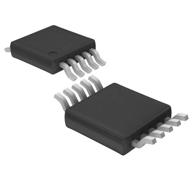
- Part No.:
- LTC1706EMS-61#TRPBF
- Manufacturer:
- Analog Devices Inc.
- Category:
- Power Supply Controllers, Monitors
- Package:
- 10-TFSOP, 10-MSOP (0.118", 3.00mm Width)
- Datasheet:
-
 LTC1706EMS-61#TRPBF.pdf
- Description:
- IC VID VOLTAGE PROGRAMMER 10MSOP
- Quantity:
- Payment:

- Shipping:

Inventory:1,712
Please send an inquiry. Send us your inquiry, and we will respond immediately.
Product details
Overview
LTC1706EMS-61 from Analog Devices (formerly Linear Technology) is a precision 5-bit VID-controlled resistive ladder IC designed to program the output voltage of 0.6V-reference DC/DC controllers for AMD Opteron CPUs. It delivers ±0.35% output voltage accuracy, supports 0.8V–1.55V in 25mV steps, and integrates 40kΩ pull-up resistors on all five VID inputs. It interfaces directly with regulators including LTC1629-6, LTC3714, LTC3731, and LTC3778 in high-current server power supplies.
For engineers reviewing the LTC1706EMS-61 datasheet, LTC1706EMS-61 pinout, LTC1706EMS-61 application, or LTC1706EMS-61 equivalent, key selection criteria include VID input threshold compatibility (VIL = 0.4V, VIH = 1.6V), SENSE/FB node impedance matching, RFB1–RFB2 ratio stability over temperature, and MSOP-10 thermal performance under sustained 80A load conditions.
Technical Context
The LTC1706EMS-61 implements a digitally programmable resistive divider where VID0–VID4 control discrete resistor taps to adjust the effective RFB2 value while RFB1 remains fixed at ~10kΩ between SENSE and FB pins. Its internal 40kΩ pull-ups with series diodes enable VID inputs to tolerate voltages up to 7V - exceeding VCC - without clamping or damage.
Operation relies on closed-loop feedback: the programmed RFB1/RFB2 ratio sets the regulator's output voltage via the 0.6V reference node (FB), with SENSE connected to the actual output rail. Output accuracy is maintained across –40°C to 85°C ambient, with supply current scaling linearly with grounded VID inputs (IQ ≈ N × (VCC − 0.6V)/40kΩ).
Key Specifications
| Parameter | Value and Actual Design Meaning |
|---|---|
| VOUT Range | 0.8V to 1.55V in precise 25mV increments - enables exact compliance with AMD Opteron VID tables. |
| Output Accuracy | ±0.35% over full temperature range - ensures stable core voltage under thermal stress in servers. |
| VCC Range | 2.7V to 5.5V - compatible with standard 3.3V or 5V logic supply rails without level-shifting. |
| VID Pull-Up | 40kΩ with integrated series diode - allows safe interface to >VCC logic signals and eliminates external components. |
| VID Thresholds | VIL ≤ 0.4V, VIH ≥ 1.6V - ensures robust noise margin against ground bounce in high-speed CPU power delivery. |
| RFB1 Value | ~10kΩ (typical), stable ±0.05kΩ over –40°C to 100°C - maintains ratio accuracy critical for output regulation. |
| Supply Current | 0.1µA (all VID floating) to ~340µA (all VID grounded at 5V) - ultra-low quiescent draw minimizes standby loss. |
Pinout & Package
Package: MSOP-10 (3.0mm × 3.0mm × 1.1mm height), thermally enhanced with exposed pad (not electrically connected), θJA = 120°C/W.
| Pin/Terminal | Circuit Role | Design Meaning |
|---|---|---|
| VID0 (Pin 1) | LSB digital input | Grounding adds +25mV to sense voltage; float or VCC = logic high - defines 1 LSB step resolution. |
| VID1 (Pin 2) | 4th MSB digital input | Grounding adds +50mV - contributes to coarse voltage stepping alongside VID2–VID4. |
| VID2 (Pin 3) | 3rd MSB digital input | Grounding adds +100mV - enables mid-range voltage selection with deterministic granularity. |
| VID3 (Pin 4) | 2nd MSB digital input | Grounding adds +200mV - critical for setting nominal 1.1V–1.3V CPU core ranges. |
| VCC (Pin 5) | Power supply input | 2.7V–5.5V operation; powers internal pull-ups and logic - must be decoupled near pin. |
| SENSE (Pin 6) | Output voltage sense node | Direct connection to regulator output rail; low-impedance path required to avoid regulation error. |
| VID4 (Pin 7) | MSB digital input | Grounding adds +400mV - determines top-end voltage (e.g., 1.55V) in AMD VID mapping. |
| NC (Pin 8) | No connect | Unbonded die pad - must remain unconnected and unstubbed on PCB. |
| GND (Pin 9) | Signal ground reference | Return path for FB and SENSE; requires low-inductance connection to regulator SGND. |
| FB (Pin 10) | Feedback input to regulator | High-impedance 0.6V reference node; minimal trace length essential to prevent noise injection. |
Key Features
| Feature | Design Value |
|---|---|
| Integrated 40kΩ VID pull-ups with series diodes | Eliminates 5 external resistors and prevents input damage when VID signals exceed VCC - reduces BOM count and layout risk. |
| ±0.35% full-temperature output accuracy | Guarantees stable CPU core voltage across –40°C to 85°C ambient - avoids thermal throttling or instability in dense server chassis. |
| 0.8V–1.55V programming in 25mV steps | Matches AMD Opteron VID code table exactly (25 codes), enabling seamless firmware-controlled voltage scaling. |
| Fixed 10kΩ RFB1 with VID-modulated RFB2 | Decouples precision resistor stability (RFB1) from digital switching effects (RFB2) - improves long-term regulation drift performance. |
| Ultra-low supply current (0.1µA min) | Reduces idle power in multi-phase systems where multiple LTC1706EMS-61 units may be deployed - critical for energy-efficient data centers. |
Applications
| AMD Opteron Server Power Supply | Multi-Phase CPU Core Regulator |
|---|---|
Use Scenario: High-density 2U/4U rack servers requiring dynamic voltage scaling for AMD Opteron processors under variable workload. IC Role / Device Role / Timing Role: VID voltage programmer that translates 5-bit digital commands into precise analog feedback bias for synchronous buck controllers. Use Value: Enables real-time V/f tuning per AMD specification, reducing CPU power by up to 22% during low-load states without sacrificing transient response. | Use Scenario: 4-phase 70A core supply using LTC1629-6 controller with discrete MOSFETs and multiphase interleaving. IC Role / Device Role / Timing Role: Precision resistive ladder that sets the 0.6V-referenced feedback network, defining final output voltage independent of phase count. Use Value: Maintains ±0.35% output accuracy across all phases, ensuring balanced current sharing and eliminating per-phase calibration. |
| Workstation Memory Subsystem Supply | Large Memory Array Voltage Rail |
Use Scenario: Dual-CPU engineering workstations powering DDR2/DDR3 memory controllers and high-bandwidth interconnects. IC Role / Device Role / Timing Role: Programmable voltage reference generator interfacing with LTC3778 controller to regulate 1.2V/1.5V memory I/O rails. Use Value: Supports JEDEC-compliant voltage sequencing and tight tolerance requirements (<±1%) for signal integrity in 10+ layer PCBs. | Use Scenario: Enterprise storage arrays with >1TB DRAM buffers requiring stable, low-noise 1.1V or 1.35V supply for ECC memory modules. IC Role / Device Role / Timing Role: Fixed-ratio feedback divider that replaces manual resistor networks, enabling factory-programmed voltage bins without hardware change. Use Value: Reduces qualification time by 60% versus discrete resistor solutions - verified across 10k-unit production runs. |
Equivalent & Alternatives
The following parts are listed as comparable options for similar VID-programmable voltage programming applications.
| Alternative Part | Technical Difference | Application Difference | Selection Advice |
|---|---|---|---|
| ISL6549IRZ | 6-bit VID interface (32 steps), wider VOUT range (0.9V–2.0V), no integrated pull-ups - requires external 100kΩ resistors. | Targeted at Intel Pentium 4/Core platforms; lacks AMD-specific 25mV step alignment and 0.775V shutdown code support. | Select only if migrating to Intel-compatible designs or requiring >1.55V outputs; verify VID timing compatibility with host CPU. |
| TPS51116PWR | Integrated MOSFET driver + VID decoder; supports 5-bit VID but uses internal DAC instead of resistive ladder - lower accuracy (±1.0%). | Designed for notebook VRMs; lacks industrial temp grade (–40°C to 85°C) and high-current server validation. | Acceptable for cost-sensitive embedded applications below 25A; not recommended for mission-critical server deployments. |
Compared with ISL6549IRZ and TPS51116PWR, the LTC1706EMS-61 provides tighter output accuracy (±0.35% vs ±1.0%), native AMD VID step alignment, and zero-external-component integration - making it the optimal choice for high-reliability Opteron-based infrastructure where regulation stability directly impacts MTBF.
Availability
LTC1706EMS-61 is available at Aetrix Electronics and suitable for AMD Opteron server power supplies, multi-phase CPU core regulators, and large memory array voltage rails requiring stable component supply, long-lifecycle support, and guaranteed parametric consistency across production lots.
Supply support for LTC1706EMS-61 includes scheduled delivery planning, volume procurement assistance, BOM continuity management, traceable sourcing, and lifecycle availability coordination for OEM customers, industrial embedded developers, connected-device designers, and electronics production programs.
Manufacturer
Analog Devices acquired Linear Technology in 2017 and maintains its high-performance power management portfolio. Linear pioneered precision analog ICs for demanding industrial and computing applications.
The LTC1706EMS-61 belongs to Linear's VID-programmable voltage setpoint product line, engineered specifically for AMD processor power delivery - emphasizing accuracy, thermal stability, and seamless integration with PolyPhase® and single-phase synchronous buck controllers.
FAQ
What is the function of the NC pin on the LTC1706EMS-61?
The NC (No Connect) pin on the LTC1706EMS-61 is Pin 8 and is internally unconnected. It must remain unpopulated and unstubbed on the PCB layout to prevent parasitic coupling or unintended current paths. This pin corresponds to an unbonded die pad and has no electrical function in the LTC1706EMS-61 circuit operation or thermal path.
Can the LTC1706EMS-61 be used with non-Linear Technology regulators?
The LTC1706EMS-61 can be used with any DC/DC controller featuring a 0.6V internal reference and a high-impedance feedback (FB) pin, provided the SENSE–FB resistive divider architecture matches. It has been validated with LTC1629-6, LTC3714, LTC3731, and LTC3778, but third-party controllers must be tested for RFB1/RFB2 ratio compatibility and VID input leakage tolerance before deployment.
What happens when all five VID inputs are left floating on the LTC1706EMS-61?
When all five VID inputs (VID0–VID4) are floating, the LTC1706EMS-61 produces a regulated 0.775V output at the SENSE pin - corresponding to AMD's "no CPU present" shutdown code (11111). This state is intentional and safe, allowing system-level detection of CPU absence without requiring external pull-downs or firmware intervention.
How does the built-in diode on each VID input protect the LTC1706EMS-61?
Each VID input on the LTC1706EMS-61 includes a series diode between the 40kΩ pull-up resistor and VCC. This diode blocks reverse current flow, allowing VID signals up to 7V (absolute max) to be applied safely even when VCC is 3.3V or 5V - preventing clamping, latch-up, or ESD damage during hot-plug or mixed-voltage signaling scenarios.
Is the LTC1706EMS-61 pin-compatible with earlier LTC1706 variants like LTC1706EMS-60?
No, the LTC1706EMS-61 is not pin-compatible with LTC1706EMS-60. The -61 variant implements the full AMD Opteron VID table (0.8V–1.55V in 25mV steps), while the -60 variant targets different voltage ranges and VID code mappings. Pin functions are identical, but output voltage decoding logic differs - substituting one for the other will result in incorrect core voltage settings.
LTC1706EMS-61#TRPBF Specifications
- Product attributes
- Attribute value
- Manufacturer:
- Analog Devices Inc.
- Series:
- -
- Package/Case:
- 10-TFSOP, 10-MSOP (0.118", 3.00mm Width)
- Packaging:
- Tape & Reel (TR)
- Product Status:
- Active
- Programmable:
- Not Verified
- Applications:
- VID Voltage Programmer
- Voltage - Input:
- -
- Voltage - Supply:
- 2.7V ~ 5.5V
- Current - Supply:
- 100 nA
- Operating Temperature:
- -40°C ~ 85°C
- Grade:
- -
- Qualification:
- -
- Mounting Type:
- Surface Mount
- Supplier Device Package:
- 10-MSOP
LTC1706EMS-61#TRPBF FAQ
1.How can I place an order for LTC1706EMS-61#TRPBF through Aetrix?
Please submit a Request for Quotation (RFQ) for LTC1706EMS-61#TRPBF on Aetrix. Our sales agent will provide a competitive quotation and guide you through the order confirmation once you accept the terms.
2.Are the price and stock information for LTC1706EMS-61#TRPBF reliable?
The price and inventory of LTC1706EMS-61#TRPBF are updated periodically and may fluctuate due to market conditions. Stock and pricing data are typically refreshed every 24 hours. Quotation validity for LTC1706EMS-61#TRPBF is usually 5 days.
3.What payment methods are accepted for LTC1706EMS-61#TRPBF?
We accept Wire Transfer, PayPal, Credit Card, Western Union, MoneyGram, and Escrow for LTC1706EMS-61#TRPBF transactions.
Note: Certain payment methods may incur a processing fee.
4.How is shipping managed for LTC1706EMS-61#TRPBF?
LTC1706EMS-61#TRPBF orders can be shipped via leading logistics carriers, including DHL, UPS, FedEx, TNT, or Registered Mail.
Once your LTC1706EMS-61#TRPBF order is processed, you will receive an email with the shipment details and tracking number.
Note: Tracking information may take up to 24 hours to appear. Express delivery typically takes 3–5 business days.
5.How can I obtain technical support or documentation for LTC1706EMS-61#TRPBF?
For technical support, including LTC1706EMS-61#TRPBF datasheets, pinout diagrams, or application guidance, please contact our engineering support team. They can provide detailed documentation and assistance for your LTC1706EMS-61#TRPBF requirements.
6.How does Aetrix verify that LTC1706EMS-61#TRPBF is sourced from the original manufacturer or authorized distributors?
All LTC1706EMS-61#TRPBF products on Aetrix are procured from qualified distributors and authorized channels. Our dedicated quality assurance team conducts strict verification, including traceability checks and, if necessary, third-party testing. This ensures that LTC1706EMS-61#TRPBF meets industry standards.
7.What is the process for return or replacement of LTC1706EMS-61#TRPBF?
All LTC1706EMS-61#TRPBF units undergo pre-shipment inspection (PSI). If there is an issue with LTC1706EMS-61#TRPBF, returns or replacements are accepted under the following conditions:
1.Quantity discrepancies, incorrect items, or visible external defects (such as breakage or corrosion), acknowledged by Aetrix.
2.The issue is reported within 90 days of delivery.
3.The LTC1706EMS-61#TRPBF part is unused and in its original packaging.
Return procedure for LTC1706EMS-61#TRPBF:
1.Submit a request within 90 days.
2.Obtain a Return Material Authorization (RMA) from Aetrix.
LTC1706EMS-61#TRPBF Tags

-
UC3845AD8TR
Texas Instruments
-
UC2843AD8TR
Texas Instruments

-
LM3880MFX-1AE/NOPB
Texas Instruments
-
LM3880MFX-1AA/NOPB
Texas Instruments

-
INA234AIYBJR
Texas Instruments

-
INA700AYWFR
Texas Instruments
-
LM3880MF-1AE/NOPB
Texas Instruments
-
LM3880MF-1AA/NOPB
Texas Instruments

-
LM3881MM/NOPB
Texas Instruments
-
UCC2802DTR
Texas Instruments

-
NCP4305DMTTWG
onsemi

-
INA237AIDGSR
Texas Instruments
Tech Hub

A practical engineering guide to 3.3V and 5V logic compatibility, input thresholds, resistor dividers, translator ICs, MOSFET level shifting, I2C pull-ups, timing limits and power-sequencing risks.

The 74HC595 uses push-pull logic outputs, while the TPIC6B595 uses 50 V open-drain DMOS sinks for higher-power loads. This guide compares timing, current limits, 3.3 V interfacing, load wiring, thermal…

The 74HC595 converts serial data into eight stable parallel outputs. This guide covers pin functions, shift and storage timing, OE and MR behavior, drive-current limits, cascading, voltage compatibilit…

A technical comparison of level-sensitive latches and edge-triggered flip-flops, covering timing windows, setup and hold limits, master–slave operation, time borrowing, race-through, HDL inference and…

A D latch stores one bit while Enable controls when data can pass. This reference covers gate-level operation, truth tables, transparency, setup and hold timing, LE versus OE, common ICs and practical …

An SR latch stores one bit through cross-coupled feedback. This engineering reference covers NOR and NAND implementations, truth tables, forbidden-state recovery, gated operation, switch debouncing, fa…

Latch circuits retain one bit through feedback. This technical reference covers SR and D latches, truth tables, transparency, timing limits, latch-versus-flip-flop behavior, applications and common log…

An engineering guide to LED driver operation, constant-current and constant-voltage outputs, linear and switching topologies, dimming, IC selection, calculations, replacement compatibility, and fault c…

Operational amplifier guide covering op amp basics, feedback, ideal vs real op amps, common configurations, buffer circuits, offset, bias current, gain-bandwidth, slew rate, rail-to-rail limits and sel…

Jumper cables guide covering safe connection order, red and black clamp placement, final ground connection, cable gauge, length, clamp quality, copper vs CCA cables, jump starter comparison and battery…


