
 My Inquiry
 My Account


Analog Devices Inc. LTC1706EMS-81#TRPBF
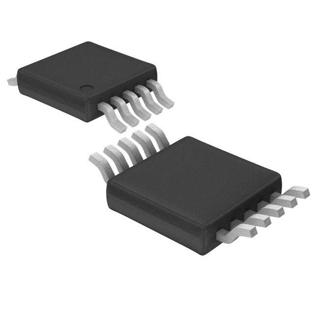
- Part No.:
- LTC1706EMS-81#TRPBF
- Manufacturer:
- Analog Devices Inc.
- Category:
- Power Supply Controllers, Monitors
- Package:
- 10-TFSOP, 10-MSOP (0.118", 3.00mm Width)
- Datasheet:
-
 LTC1706EMS-81#TRPBF.pdf
- Description:
- IC VID VOLTAGE PROGRAMMER 10MSOP
- Quantity:
- Payment:

- Shipping:

Inventory:4,709
Please send an inquiry. Send us your inquiry, and we will respond immediately.
Product details
Overview
LTC1706EMS-81#TRPBF from Analog Devices (formerly Linear Technology) is a precision 5-bit VID-controlled resistive ladder IC designed to program the output voltage of 0.8V-referenced DC/DC converters. It delivers ±0.25% output voltage accuracy across 1.3V–2.05V (50mV steps) and 2.1V–3.5V (100mV steps), supports Intel VRM 8.4 desktop specification, and operates from 2.7V–5.5V supply. It enables high-current multiphase CPU core power supplies in Pentium II/III and AMD Athlon platforms.
For engineers reviewing the LTC1706EMS-81#TRPBF datasheet, LTC1706EMS-81#TRPBF pinout, LTC1706EMS-81#TRPBF application, or LTC1706EMS-81#TRPBF equivalent, key selection criteria include VID input pull-up resistance (40kΩ), RFB1–SENSE/FB resistance (12–28kΩ), output voltage error tolerance (±0.25%), operating temperature range (–40°C to 85°C), and MSOP-10 package compatibility with high-density PCB layouts.
Technical Context
The LTC1706EMS-81#TRPBF implements a digitally programmable resistive divider network where VID0–VID4 control binary-weighted current paths to adjust the effective bottom feedback resistor (RFB2) while RFB1 remains fixed at ~20kΩ between SENSE and FB pins. VID4 selects between two output ranges, enabling precise mapping to Intel VRM 8.4 voltage codes.
Each VID input integrates a 40kΩ pull-up resistor in series with a diode to VCC, allowing safe operation with input voltages exceeding VCC (up to 7V absolute max) without clamping. The device draws only 0.1–5µA quiescent current when all VID inputs float, rising linearly with grounded VID count per IQ = N(VCC – 0.6V)/40kΩ.
Key Specifications
| Parameter | Value and Actual Design Meaning |
|---|---|
| Output Voltage Range | 1.3V–2.05V (50mV steps) or 2.1V–3.5V (100mV steps); enables full VRM 8.4 compliance for CPU core supplies |
| Output Voltage Accuracy | ±0.25% (1.3V–2.05V range); ensures tight regulation under load transients in high-performance computing |
| VCC Supply Range | 2.7V–5.5V; compatible with standard 3.3V and 5V system rails without level-shifting |
| VID Pull-Up Resistance | 40kΩ per input; defines logic threshold robustness and minimizes external component count |
| RFB1 (SENSE–FB) | 12–28kΩ typical; sets base feedback ratio for 0.8V reference-based regulators like LTC1629/LTC1929 |
| Operating Temp Range | –40°C to +85°C; qualified for industrial-grade server and workstation environments |
| Supply Current (IVCC) | 0.1–5µA (all VID floating); ultra-low standby power critical for always-on system management |
Pinout & Package
Package: 10-lead MSOP (MS10), 3.0mm × 3.0mm footprint, 0.5mm pitch, thermal pad optional. Pin 8 is NC; pin 9 is GND; pin 10 is FB - all defined per LTC DWG #05-08-1661.
| Pin/Terminal | Circuit Role | Design Meaning |
|---|---|---|
| VID0 (Pin 1) | LSB digital programming input | Adds 50mV (VID4=0) or 100mV (VID4=1) to sense voltage; ground = logic low, float/VCC = logic high |
| VID1 (Pin 2) | 3rd MSB digital programming input | Adds 100mV (VID4=0) or 200mV (VID4=1); enables fine-grained voltage step resolution |
| VID2 (Pin 3) | 2nd MSB digital programming input | Adds 200mV (VID4=0) or 400mV (VID4=1); critical for mid-range voltage coding |
| VID3 (Pin 4) | MSB digital programming input | Adds 400mV (VID4=0) or 800mV (VID4=1); determines coarse voltage band within range |
| VCC (Pin 5) | Power supply input | 2.7V–5.5V operation; powers internal pull-ups and logic; source of VID clamp diodes |
| SENSE (Pin 6) | Regulator output voltage node | Connects directly to converter output or VDIFFOUT (LTC1629/LTC1929); enables remote sensing |
| VID4 (Pin 7) | Range select bit | VID4=0 → 1.3V–2.05V; VID4=1 → 2.1V–3.5V; defines VID code interpretation matrix |
| NC (Pin 8) | No connect | Not bonded; must remain unconnected per datasheet; no routing or thermal considerations |
| GND (Pin 9) | Signal ground reference | Low-impedance return path for FB and SENSE; requires dedicated SGND plane connection |
| FB (Pin 10) | 0.8V feedback input | High-impedance node connected to EAIN (LTC1629) or FB pin of 0.8V-reference regulators |
Key Features
| Feature | Design Value |
|---|---|
| Fully compliant with Intel VRM 8.4 desktop specification | Validated VID code mapping (Table 1) matches Pentium II/III voltage tables; eliminates firmware-level translation |
| Built-in 40kΩ pull-up resistors on all VID inputs | Removes need for 5 external pull-ups; reduces BOM count and layout area; diode-clamped for >VCC tolerance |
| ±0.25% output voltage accuracy over temperature | Ensures stable CPU core voltage across –40°C to +85°C; avoids derating or guard-banding in thermal design |
| Supports up to 70A multiphase applications | Validated in 4-phase LTC1629 reference design (TA02); maintains accuracy with distributed current sharing |
| Direct interface with LTC1629, LTC1929, LTC1735, and other 0.8V-reference regulators | Pin-compatible FB/SENSE/GND connections eliminate adapter circuitry; simplifies migration across LTC DC/DC families |
Applications
| Intel Pentium II/III Processor Power Supply | AMD Athlon™ Processor Power Supply |
|---|---|
Use Scenario: Desktop motherboard delivering dynamically scaled core voltage to Pentium II/III CPUs under BIOS or OS control. IC Role / Device Role / Timing Role: VID voltage programmer that converts 5-bit digital commands into precise analog feedback bias for synchronous buck controllers. Use Value: Enables real-time voltage scaling (e.g., 1.8V idle → 2.0V turbo) with <±0.25% error, meeting Intel VRM 8.4 timing and accuracy requirements. |
Use Scenario: High-performance desktop platform supplying adaptive core voltage to AMD Athlon processors during frequency transitions. IC Role / Device Role / Timing Role: Digital-to-resistive converter generating regulated sense voltage for 0.8V-reference DC/DC controllers in multi-phase topologies. Use Value: Delivers 2.1V–3.5V range with 100mV steps and guaranteed ±0.25% accuracy, satisfying AMD's voltage tolerance specifications for stable overclocking. |
| Workstations and Servers | Large Memory Array Supply |
Use Scenario: Dual-CPU server board requiring tightly regulated, high-current (≥70A) core voltage with remote sensing and thermal compensation. IC Role / Device Role / Timing Role: Precision feedback network element interfacing with PolyPhase™ controllers (e.g., LTC1629) to maintain voltage stability across multiple phases and PCB traces. Use Value: Maintains <±0.25% output error over –40°C to +85°C ambient, ensuring reliable operation in thermally demanding rack-mounted environments. |
Use Scenario: DDR SDRAM memory subsystem requiring clean, low-noise 2.5V or 2.6V supply with fast transient response and minimal voltage droop. IC Role / Device Role / Timing Role: Fixed-voltage configuration mode (e.g., VID4=0, VID0–VID3 grounded) providing stable 2.05V output for memory I/O or termination rails. Use Value: Eliminates need for trimming potentiometers or discrete resistor networks; achieves factory-calibrated accuracy without post-assembly calibration. |
Equivalent & Alternatives
The following parts are listed as comparable options for similar VID voltage programming applications.
| Alternative Part | Technical Difference | Application Difference | Selection Advice |
|---|---|---|---|
| LTC1706EMS-82#TRPBF | Same pinout and function but supports VRM 8.5 (1.15V–2.05V @ 25mV steps); different VID code mapping | Required for newer Pentium III processors with extended low-voltage support; not interchangeable with VRM 8.4 systems | Select LTC1706EMS-82#TRPBF only when VRM 8.5 compliance is mandated by CPU specification. |
| LTC1709CG#TRPBF | Integrated 2-phase synchronous controller with built-in 5-bit VID decoder; includes gate drivers, current sensing, and PLL | Replaces discrete controller + VID IC combo; targets space-constrained designs needing integrated solution | Choose LTC1709CG#TRPBF when consolidating bill-of-material and reducing PCB area outweighs need for modular VID programming. |
Compared with LTC1706EMS-81#TRPBF, the LTC1706EMS-82#TRPBF offers finer 25mV voltage resolution below 2.05V but lacks backward compatibility with VRM 8.4 code tables, while the LTC1709CG#TRPBF trades flexibility for integration-eliminating external MOSFET drivers but fixing phase count and topology.
Availability
LTC1706EMS-81#TRPBF is available at Aetrix Electronics and suitable for Intel Pentium II/III processor power supplies, AMD Athlon™ platform designs, and high-current workstation/server DC/DC applications requiring stable component supply, long-term lifecycle assurance, and traceable sourcing.
Supply support for LTC1706EMS-81#TRPBF includes scheduled delivery planning, volume procurement assistance, BOM continuity management, traceable sourcing, and lifecycle availability coordination for OEM customers, industrial embedded developers, connected-device designers, and electronics production programs.
Manufacturer
Analog Devices acquired Linear Technology in 2017 and maintains its legacy precision analog and power management product lines. Linear was founded in 1981 and specialized in high-performance linear ICs, DC/DC controllers, and signal conditioning solutions.
The LTC1706EMS-81#TRPBF belongs to Linear's VID-programmable voltage setpoint family, engineered specifically for Intel VRM-compliant CPU core power delivery in desktop, workstation, and entry-server platforms requiring high accuracy and low quiescent current.
FAQ
What is the primary function of the LTC1706EMS-81#TRPBF in a power supply design?
The LTC1706EMS-81#TRPBF serves as a precision 5-bit VID-controlled resistive ladder that programs the output voltage of 0.8V-referenced DC/DC converters. It replaces manual resistor networks by digitally configuring the feedback divider ratio via VID0–VID4 inputs, enabling dynamic voltage scaling per Intel VRM 8.4. The LTC1706EMS-81#TRPBF directly interfaces with regulators like the LTC1629 and LTC1929 to deliver accurate, stable core voltages from 1.3V to 3.5V.
Does the LTC1706EMS-81#TRPBF require external pull-up resistors on its VID inputs?
No, the LTC1706EMS-81#TRPBF integrates internal 40kΩ pull-up resistors on all five VID inputs (VID0–VID4), each with a series diode to VCC. This eliminates the need for external pull-ups and allows safe operation with input voltages exceeding VCC (up to 7V absolute max). Grounding a VID pin pulls it low; leaving it floating or connecting to VCC yields a logic high. The LTC1706EMS-81#TRPBF's internal structure ensures correct logic interpretation without external components.
Which DC/DC controllers are explicitly supported by the LTC1706EMS-81#TRPBF according to the datasheet?
The LTC1706EMS-81#TRPBF is validated to program the LTC1622, LTC1628, LTC1629, LTC1702, LTC1735, LTC1735-1, LTC1772, and LTC1929 - all of which feature an internal 0.8V reference and compatible feedback architecture. Connection is direct: FB pin to regulator's EAIN or FB node, SENSE to output or VDIFFOUT, and GND to signal ground. The LTC1706EMS-81#TRPBF datasheet confirms interoperability with these specific Linear Technology parts and notes future compatible devices are available upon factory consultation.
How does the VID4 pin affect voltage programming on the LTC1706EMS-81#TRPBF?
The VID4 pin on the LTC1706EMS-81#TRPBF acts as the range-select bit: when VID4 = LOW (grounded), the device outputs voltages from 1.3V to 2.05V in 50mV increments; when VID4 = HIGH (floated or tied to VCC), it outputs 2.1V to 3.5V in 100mV increments. This dual-range architecture aligns precisely with Intel VRM 8.4 specifications. The LTC1706EMS-81#TRPBF uses VID4 to determine how the remaining VID0–VID3 bits weight their contributions (e.g., VID0 adds 50mV in low range, 100mV in high range).
What is the maximum allowable junction temperature and thermal resistance for the LTC1706EMS-81#TRPBF in MSOP-10 package?
The LTC1706EMS-81#TRPBF has a maximum junction temperature (TJMAX) of 110°C and a specified thermal resistance θJA of 120°C/W for the MS10 (MSOP-10) package under standard JEDEC test conditions. This value assumes no thermal pad soldering; adding a thermal pad to a copper pour can significantly reduce θJA. The device is rated for continuous operation from –40°C to +85°C ambient, and its 0.1–5µA supply current minimizes self-heating, making thermal design straightforward in typical motherboard layouts. The LTC1706EMS-81#TRPBF datasheet specifies these limits in the "Absolute Maximum Ratings" and "Package/Order Information" sections.
LTC1706EMS-81#TRPBF Specifications
- Product attributes
- Attribute value
- Manufacturer:
- Analog Devices Inc.
- Series:
- -
- Package/Case:
- 10-TFSOP, 10-MSOP (0.118", 3.00mm Width)
- Packaging:
- Tape & Reel (TR)
- Product Status:
- Active
- Programmable:
- Not Verified
- Applications:
- VID Voltage Programmer
- Voltage - Input:
- -
- Voltage - Supply:
- 2.7V ~ 5.5V
- Current - Supply:
- 100 nA
- Operating Temperature:
- -40°C ~ 85°C
- Grade:
- -
- Qualification:
- -
- Mounting Type:
- Surface Mount
- Supplier Device Package:
- 10-MSOP
LTC1706EMS-81#TRPBF FAQ
1.How can I place an order for LTC1706EMS-81#TRPBF through Aetrix?
Please submit a Request for Quotation (RFQ) for LTC1706EMS-81#TRPBF on Aetrix. Our sales agent will provide a competitive quotation and guide you through the order confirmation once you accept the terms.
2.Are the price and stock information for LTC1706EMS-81#TRPBF reliable?
The price and inventory of LTC1706EMS-81#TRPBF are updated periodically and may fluctuate due to market conditions. Stock and pricing data are typically refreshed every 24 hours. Quotation validity for LTC1706EMS-81#TRPBF is usually 5 days.
3.What payment methods are accepted for LTC1706EMS-81#TRPBF?
We accept Wire Transfer, PayPal, Credit Card, Western Union, MoneyGram, and Escrow for LTC1706EMS-81#TRPBF transactions.
Note: Certain payment methods may incur a processing fee.
4.How is shipping managed for LTC1706EMS-81#TRPBF?
LTC1706EMS-81#TRPBF orders can be shipped via leading logistics carriers, including DHL, UPS, FedEx, TNT, or Registered Mail.
Once your LTC1706EMS-81#TRPBF order is processed, you will receive an email with the shipment details and tracking number.
Note: Tracking information may take up to 24 hours to appear. Express delivery typically takes 3–5 business days.
5.How can I obtain technical support or documentation for LTC1706EMS-81#TRPBF?
For technical support, including LTC1706EMS-81#TRPBF datasheets, pinout diagrams, or application guidance, please contact our engineering support team. They can provide detailed documentation and assistance for your LTC1706EMS-81#TRPBF requirements.
6.How does Aetrix verify that LTC1706EMS-81#TRPBF is sourced from the original manufacturer or authorized distributors?
All LTC1706EMS-81#TRPBF products on Aetrix are procured from qualified distributors and authorized channels. Our dedicated quality assurance team conducts strict verification, including traceability checks and, if necessary, third-party testing. This ensures that LTC1706EMS-81#TRPBF meets industry standards.
7.What is the process for return or replacement of LTC1706EMS-81#TRPBF?
All LTC1706EMS-81#TRPBF units undergo pre-shipment inspection (PSI). If there is an issue with LTC1706EMS-81#TRPBF, returns or replacements are accepted under the following conditions:
1.Quantity discrepancies, incorrect items, or visible external defects (such as breakage or corrosion), acknowledged by Aetrix.
2.The issue is reported within 90 days of delivery.
3.The LTC1706EMS-81#TRPBF part is unused and in its original packaging.
Return procedure for LTC1706EMS-81#TRPBF:
1.Submit a request within 90 days.
2.Obtain a Return Material Authorization (RMA) from Aetrix.
LTC1706EMS-81#TRPBF Tags

-
UC3845AD8TR
Texas Instruments
-
UC2843AD8TR
Texas Instruments

-
LM3880MFX-1AE/NOPB
Texas Instruments
-
LM3880MFX-1AA/NOPB
Texas Instruments

-
INA234AIYBJR
Texas Instruments

-
INA700AYWFR
Texas Instruments
-
LM3880MF-1AE/NOPB
Texas Instruments
-
LM3880MF-1AA/NOPB
Texas Instruments

-
LM3881MM/NOPB
Texas Instruments
-
UCC2802DTR
Texas Instruments

-
NCP4305DMTTWG
onsemi

-
INA237AIDGSR
Texas Instruments
Tech Hub

A practical engineering guide to 3.3V and 5V logic compatibility, input thresholds, resistor dividers, translator ICs, MOSFET level shifting, I2C pull-ups, timing limits and power-sequencing risks.

The 74HC595 uses push-pull logic outputs, while the TPIC6B595 uses 50 V open-drain DMOS sinks for higher-power loads. This guide compares timing, current limits, 3.3 V interfacing, load wiring, thermal…

The 74HC595 converts serial data into eight stable parallel outputs. This guide covers pin functions, shift and storage timing, OE and MR behavior, drive-current limits, cascading, voltage compatibilit…

A technical comparison of level-sensitive latches and edge-triggered flip-flops, covering timing windows, setup and hold limits, master–slave operation, time borrowing, race-through, HDL inference and…

A D latch stores one bit while Enable controls when data can pass. This reference covers gate-level operation, truth tables, transparency, setup and hold timing, LE versus OE, common ICs and practical …

An SR latch stores one bit through cross-coupled feedback. This engineering reference covers NOR and NAND implementations, truth tables, forbidden-state recovery, gated operation, switch debouncing, fa…

Latch circuits retain one bit through feedback. This technical reference covers SR and D latches, truth tables, transparency, timing limits, latch-versus-flip-flop behavior, applications and common log…

An engineering guide to LED driver operation, constant-current and constant-voltage outputs, linear and switching topologies, dimming, IC selection, calculations, replacement compatibility, and fault c…

Operational amplifier guide covering op amp basics, feedback, ideal vs real op amps, common configurations, buffer circuits, offset, bias current, gain-bandwidth, slew rate, rail-to-rail limits and sel…

Jumper cables guide covering safe connection order, red and black clamp placement, final ground connection, cable gauge, length, clamp quality, copper vs CCA cables, jump starter comparison and battery…


