
 My Inquiry
 My Account


Analog Devices Inc. LTC2941IDCB#TRMPBF
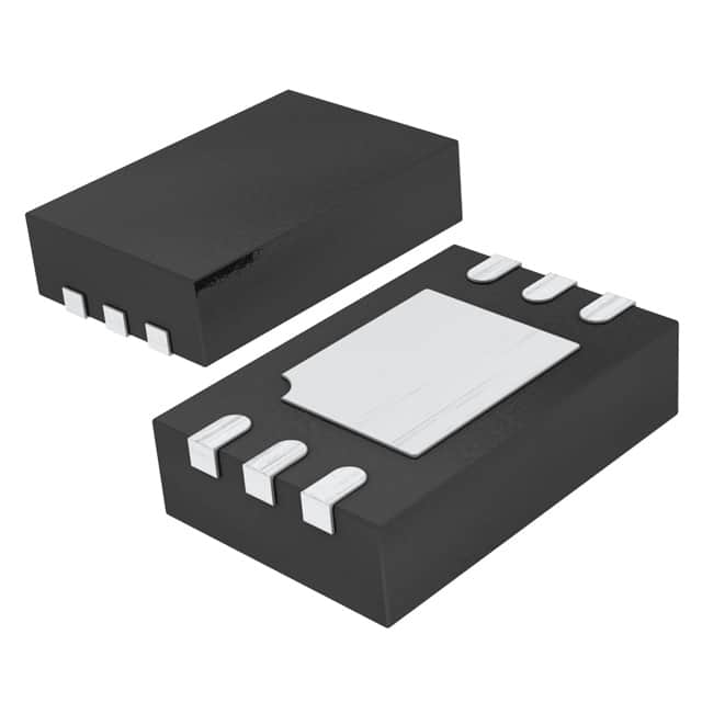
- Part No.:
- LTC2941IDCB#TRMPBF
- Manufacturer:
- Analog Devices Inc.
- Category:
- Battery Management
- Package:
- 6-WFDFN Exposed Pad
- Datasheet:
-
 LTC2941IDCB#TRMPBF.pdf
- Description:
- IC BATT MON LI-ION 1CELL 6DFN
- Quantity:
- Payment:

- Shipping:

Inventory:3,223
Please send an inquiry. Send us your inquiry, and we will respond immediately.
Product details
Overview
LTC2941IDCB#TRMPBF from Analog Devices is a precision battery gas gauge IC for single-cell Li-Ion systems, performing high-side coulomb counting with ±1% total charge accuracy, ±50mV differential sense voltage range, and SMBus/I²C interface (7-bit address 0x64). It operates from 2.7V to 5.5V and delivers <100µA quiescent current, enabling accurate state-of-charge monitoring in space-constrained portable devices.
For engineers reviewing the LTC2941IDCB#TRMPBF datasheet, LTC2941IDCB#TRMPBF pinout, LTC2941IDCB#TRMPBF application, or LTC2941IDCB#TRMPBF equivalent, key selection considerations include its 6-pin DFN (2mm × 3mm) high-side sensing architecture, programmable charge thresholds, alert/charge-complete dual-mode AL/CC pin, and guaranteed ±1% charge error over –40°C to +85°C.
Technical Context
The LTC2941IDCB#TRMPBF integrates an auto-zeroed differential analog integrator that converts sensed current (via external RSENSE) into accumulated charge stored in 16-bit registers C/D. Its internal prescaler (M = 1–128, default 128) scales integration time to match battery capacity while maintaining resolution.
It features dual-function AL/CC pin configurable via control register B[2:1] as either SMBus-compliant open-drain alert output or charge-complete input, plus VBAT undervoltage monitoring (selectable 2.8V/2.9V/3.0V thresholds) and UVLO detection at 2.45V–2.7V on SENSE+.
Key Specifications
| Parameter | Value and Actual Design Meaning |
|---|---|
| Operating Voltage | 2.7V to 5.5V on SENSE+ - supports full single-cell Li-Ion range without external LDO. |
| Charge Accuracy | ±1% over ±10mV to ±50mV sense voltage - enables reliable SoC estimation across discharge profile. |
| Sense Range | ±50mV differential (SENSE+ to SENSE–) - sets max RSENSE = 500mΩ @ 100mA, minimizing power loss. |
| Quiescent Current | <100µA active, <2.5µA shutdown - extends battery life in always-on monitoring applications. |
| I²C Address | Fixed 7-bit address 0x64 (1100100) - eliminates address conflict risk in multi-device bus systems. |
| Temperature Range | –40°C to +85°C - qualified for industrial and extended-temperature portable electronics. |
| Package | 6-pin 2mm × 3mm DFN with exposed pad (not connected) - enables compact PCB layout and thermal management. |
Pinout & Package
Package: 6-lead plastic DFN (2mm × 3mm), exposed pad (Pin 7) unconnected. Designed for high-side current sensing in battery-powered systems with minimal board area.
| Pin | Circuit Role | Design Meaning |
|---|---|---|
| 1 (SENSE+) | Positive current sense input & power supply | Connects to load/charger side of sense resistor; supplies device; accepts 2.7–5.5V. |
| 2 (GND) | Device ground reference | Must connect directly to battery negative terminal to avoid ground loop errors. |
| 3 (SCL) | I²C/SMBus clock input | Open-drain compatible; supports up to 400kHz fast-mode timing. |
| 4 (SDA) | I²C/SMBus bidirectional data line | Open-drain; requires external pull-up; shares bus with other I²C slaves. |
| 5 (AL/CC) | Configurable alert/output or charge-complete input | Default: open-drain alert output per SMBus protocol; reconfigurable to logic input for charger signaling. |
| 6 (SENSE–) | Negative current sense input | Connects to battery positive terminal side of sense resistor; differential input with ±50mV limit. |
Key Features
| Feature | Design Value |
|---|---|
| High-side coulomb counting | Eliminates need for low-side shunt placement, preserving system ground integrity and simplifying PCB routing. |
| Programmable charge thresholds | Independent high/low 16-bit limits (registers E–H) enable precise full/empty detection and charge cycle control. |
| VBAT monitoring with selectable thresholds | Three user-selectable undervoltage alerts (2.8V/2.9V/3.0V) provide early battery depletion warning without external comparators. |
| Shutdown mode with register retention | Reduces current to <2.5µA while preserving accumulated charge and configuration registers for instant wake-up. |
| Auto-zeroed analog integrator | Compensates for offset drift over temperature/time, ensuring stable ±1% accuracy across –40°C to +85°C. |
Applications
| Smartphone Battery Management | Portable Medical Device Monitoring |
|---|---|
|
Use Scenario: Real-time state-of-charge tracking during dynamic load changes in LTE-enabled smartphones with 3.7V Li-Ion cells. IC Role / Device Role / Timing Role: High-side coulomb counter measuring bidirectional current flow between battery and PMIC/load, reporting via I²C every 100ms. Use Value: Enables accurate battery remaining time estimation within ±3% error despite varying RF transmit power and display brightness. |
Use Scenario: Continuous battery health monitoring in handheld ECG analyzers operating 24/7 on rechargeable Li-Ion packs. IC Role / Device Role / Timing Role: Primary gas gauge providing accumulated charge delta to MCU firmware for predictive low-battery shutdown and calibration logging. Use Value: Extends field service life by preventing unexpected shutdown during critical patient measurements using validated ±1% charge integration. |
| Wireless Headphone Charging Case | Industrial Handheld Scanner |
|
Use Scenario: Dual-battery SoC tracking in compact charging cases that simultaneously power and recharge TWS earbuds. IC Role / Device Role / Timing Role: Dedicated coulomb counter for main case battery, interfacing with host MCU via I²C to report charge status and alert at 10% remaining. Use Value: Delivers consistent user-facing battery percentage across 500+ charge cycles without manual recalibration due to stable high-side sensing. |
Use Scenario: Ruggedized barcode scanner used in warehouse environments with wide ambient temperature swings (–20°C to +60°C). IC Role / Device Role / Timing Role: Industrial-grade gas gauge operating across –40°C to +85°C, triggering low-voltage alerts before battery brownout affects scan engine performance. Use Value: Prevents data loss during scanning sessions by initiating graceful shutdown at precisely calibrated 2.85V threshold, verified per MIL-STD-810H thermal cycling. |
Equivalent & Alternatives
The following parts are listed as comparable options for similar battery gas gauge applications.
| Alternative Part | Technical Difference | Application Difference | Selection Advice |
|---|---|---|---|
| MAX17048G+T | Uses model-based fuel-gauge algorithm (Impedance Track™); no external sense resistor required; 1.8V–5.5V supply; 12-bit ADC resolution. | Higher SoC accuracy in aging batteries but requires characterization; less suitable for high-current pulse loads where coulomb counting excels. | Select MAX17048G+T when battery model availability and long-term aging compensation outweigh need for ultra-low-power coulomb integration. |
| BQ27426YZFT | Integrated 20mΩ sense resistor; supports Li-Ion/Li-Poly only; 2.5V–4.5V supply; includes built-in temperature sensor and protection logic. | Reduces BOM count but limits flexibility in sense resistor selection and high-voltage (>4.5V) operation; fixed 128-segment learning table. | Select BQ27426YZFT when minimizing component count and leveraging TI's battery learning algorithms is prioritized over design flexibility and extended voltage range. |
Compared with MAX17048G+T and BQ27426YZFT, the LTC2941IDCB#TRMPBF provides deterministic, resistor-based coulomb counting with guaranteed ±1% accuracy across temperature, making it optimal for applications requiring traceable, physics-based charge measurement without battery-specific modeling.
Availability
LTC2941IDCB#TRMPBF is available at Aetrix Electronics and suitable for smartphone battery management, portable medical device monitoring, wireless headphone charging cases, and industrial handheld scanners requiring stable component supply across extended temperature ranges.
Supply support for LTC2941IDCB#TRMPBF includes scheduled delivery planning, volume procurement assistance, BOM continuity management, traceable sourcing, and lifecycle availability coordination for OEM customers, industrial embedded developers, connected-device designers, and electronics production programs.
Manufacturer
Analog Devices, Inc. is a global leader in high-performance analog, mixed-signal, and digital signal processing semiconductors, serving industrial, automotive, communications, and healthcare markets.
The LTC2941IDCB#TRMPBF belongs to Analog Devices' precision power monitoring product line, designed specifically for high-accuracy, low-power battery gas gauging in portable and energy-constrained systems.
FAQ
What is the absolute maximum voltage rating for SENSE+ on the LTC2941IDCB#TRMPBF?
The LTC2941IDCB#TRMPBF specifies an absolute maximum SENSE+ voltage of 6V, with recommended operating range 2.7V to 5.5V. Exceeding 6V may cause permanent damage. The device includes undervoltage lockout (UVLO) that activates below ~2.45V to prevent erroneous operation during power-up or brownout conditions.
How does the LTC2941IDCB#TRMPBF achieve ±1% charge accuracy, and under what conditions is this guaranteed?
The LTC2941IDCB#TRMPBF achieves ±1% total charge error over a differential sense voltage range of ±10mV to ±50mV at 25°C, and ±1.5% across the full –40°C to +85°C operating range. This is enabled by its auto-zeroed differential analog integrator and precision internal reference, with error measured against known current sources and timed integration intervals.
Can the AL/CC pin on the LTC2941IDCB#TRMPBF be used simultaneously for alert output and charge-complete input?
No - the AL/CC pin on the LTC2941IDCB#TRMPBF is strictly dual-mode but not simultaneous: bits B[2:1] in the control register configure it exclusively as either SMBus alert output ([10]) or charge-complete input ([01]). Setting [11] is prohibited and may result in undefined behavior; [00] disables the pin entirely.
What is the function of the exposed pad on the LTC2941IDCB#TRMPBF DFN package?
The exposed pad (Pin 7) on the LTC2941IDCB#TRMPBF 6-lead DFN package is electrically unconnected and must remain floating - it is not tied to GND or any internal node. Its purpose is mechanical stability and thermal dissipation; soldering it to a thermal pad improves heat transfer but introduces no electrical connection.
Does the LTC2941IDCB#TRMPBF support standard-mode (100kHz) and fast-mode (400kHz) I²C communication?
Yes - the LTC2941IDCB#TRMPBF supports both standard-mode (up to 100kHz) and fast-mode (up to 400kHz) I²C timing, with specified tSU,STA, tHD,STA, and tBUF parameters validated across –40°C to +85°C. It does not support fast-mode plus (1MHz) or high-speed mode.
LTC2941IDCB#TRMPBF Specifications
- Product attributes
- Attribute value
- Manufacturer:
- Analog Devices Inc.
- Series:
- -
- Package/Case:
- 6-WFDFN Exposed Pad
- Packaging:
- Tape & Reel (TR)
- Product Status:
- Last Time Buy
- Function:
- Battery Monitor
- Battery Chemistry:
- Lithium Ion
- Number of Cells:
- 1
- Fault Protection:
- -
- Interface:
- I2C
- Operating Temperature:
- -40°C ~ 85°C (TA)
- Grade:
- -
- Qualification:
- -
- Mounting Type:
- Surface Mount
- Supplier Device Package:
- 6-DFN (2x3)
LTC2941IDCB#TRMPBF FAQ
1.How can I place an order for LTC2941IDCB#TRMPBF through Aetrix?
Please submit a Request for Quotation (RFQ) for LTC2941IDCB#TRMPBF on Aetrix. Our sales agent will provide a competitive quotation and guide you through the order confirmation once you accept the terms.
2.Are the price and stock information for LTC2941IDCB#TRMPBF reliable?
The price and inventory of LTC2941IDCB#TRMPBF are updated periodically and may fluctuate due to market conditions. Stock and pricing data are typically refreshed every 24 hours. Quotation validity for LTC2941IDCB#TRMPBF is usually 5 days.
3.What payment methods are accepted for LTC2941IDCB#TRMPBF?
We accept Wire Transfer, PayPal, Credit Card, Western Union, MoneyGram, and Escrow for LTC2941IDCB#TRMPBF transactions.
Note: Certain payment methods may incur a processing fee.
4.How is shipping managed for LTC2941IDCB#TRMPBF?
LTC2941IDCB#TRMPBF orders can be shipped via leading logistics carriers, including DHL, UPS, FedEx, TNT, or Registered Mail.
Once your LTC2941IDCB#TRMPBF order is processed, you will receive an email with the shipment details and tracking number.
Note: Tracking information may take up to 24 hours to appear. Express delivery typically takes 3–5 business days.
5.How can I obtain technical support or documentation for LTC2941IDCB#TRMPBF?
For technical support, including LTC2941IDCB#TRMPBF datasheets, pinout diagrams, or application guidance, please contact our engineering support team. They can provide detailed documentation and assistance for your LTC2941IDCB#TRMPBF requirements.
6.How does Aetrix verify that LTC2941IDCB#TRMPBF is sourced from the original manufacturer or authorized distributors?
All LTC2941IDCB#TRMPBF products on Aetrix are procured from qualified distributors and authorized channels. Our dedicated quality assurance team conducts strict verification, including traceability checks and, if necessary, third-party testing. This ensures that LTC2941IDCB#TRMPBF meets industry standards.
7.What is the process for return or replacement of LTC2941IDCB#TRMPBF?
All LTC2941IDCB#TRMPBF units undergo pre-shipment inspection (PSI). If there is an issue with LTC2941IDCB#TRMPBF, returns or replacements are accepted under the following conditions:
1.Quantity discrepancies, incorrect items, or visible external defects (such as breakage or corrosion), acknowledged by Aetrix.
2.The issue is reported within 90 days of delivery.
3.The LTC2941IDCB#TRMPBF part is unused and in its original packaging.
Return procedure for LTC2941IDCB#TRMPBF:
1.Submit a request within 90 days.
2.Obtain a Return Material Authorization (RMA) from Aetrix.
LTC2941IDCB#TRMPBF Tags

-
BQ29700DSER
Texas Instruments

-
S-8241ABKMC-GBKT2G
ABLIC Inc.
-
S-8241ABPMC-GBPT2G
ABLIC Inc.

-
BQ27427YZFR
Texas Instruments

-
BQ27426YZFR
Texas Instruments

-
STC3117IJT
STMicroelectronics

-
STC3115IJT
STMicroelectronics

-
BQ76925RGER
Texas Instruments
-
NPM1100-QDAA-R
Nordic Semiconductor ASA

-
BQ27441DRZR-G1A
Texas Instruments

-
STC3115AIQT
STMicroelectronics

-
S-8252AAL-M6T1U
ABLIC Inc.
Tech Hub

A practical engineering guide to 3.3V and 5V logic compatibility, input thresholds, resistor dividers, translator ICs, MOSFET level shifting, I2C pull-ups, timing limits and power-sequencing risks.

The 74HC595 uses push-pull logic outputs, while the TPIC6B595 uses 50 V open-drain DMOS sinks for higher-power loads. This guide compares timing, current limits, 3.3 V interfacing, load wiring, thermal…

The 74HC595 converts serial data into eight stable parallel outputs. This guide covers pin functions, shift and storage timing, OE and MR behavior, drive-current limits, cascading, voltage compatibilit…

A technical comparison of level-sensitive latches and edge-triggered flip-flops, covering timing windows, setup and hold limits, master–slave operation, time borrowing, race-through, HDL inference and…

A D latch stores one bit while Enable controls when data can pass. This reference covers gate-level operation, truth tables, transparency, setup and hold timing, LE versus OE, common ICs and practical …

An SR latch stores one bit through cross-coupled feedback. This engineering reference covers NOR and NAND implementations, truth tables, forbidden-state recovery, gated operation, switch debouncing, fa…

Latch circuits retain one bit through feedback. This technical reference covers SR and D latches, truth tables, transparency, timing limits, latch-versus-flip-flop behavior, applications and common log…

An engineering guide to LED driver operation, constant-current and constant-voltage outputs, linear and switching topologies, dimming, IC selection, calculations, replacement compatibility, and fault c…

Operational amplifier guide covering op amp basics, feedback, ideal vs real op amps, common configurations, buffer circuits, offset, bias current, gain-bandwidth, slew rate, rail-to-rail limits and sel…

Jumper cables guide covering safe connection order, red and black clamp placement, final ground connection, cable gauge, length, clamp quality, copper vs CCA cables, jump starter comparison and battery…


