
 My Inquiry
 My Account


Analog Devices Inc. LTC2956IMS-1#TRPBF
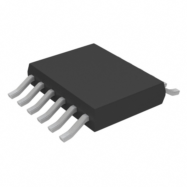
- Part No.:
- LTC2956IMS-1#TRPBF
- Manufacturer:
- Analog Devices Inc.
- Category:
- Power Supply Controllers, Monitors
- Package:
- 12-TSSOP (0.118", 3.00mm Width)
- Datasheet:
-
 LTC2956IMS-1#TRPBF.pdf
- Description:
- IC PB ON/OFF CONTROLLER 12MSOP
- Quantity:
- Payment:

- Shipping:

Inventory:2,082
Please send an inquiry. Send us your inquiry, and we will respond immediately.
Product details
Overview
LTC2956IMS-1#TRPBF from Analog Devices (formerly Linear Technology) is a micropower, wide-input wake-up timer IC with pushbutton control and active-high enable output, operating from 1.5V to 36V supply, featuring 250ms–39-day configurable wake period, 800nA quiescent current in awake state, and –40°C to +85°C industrial temperature range. It enables periodic system activation for battery-powered data acquisition or intervalometer tasks.
For engineers reviewing the LTC2956IMS-1#TRPBF datasheet, LTC2956IMS-1#TRPBF pinout, LTC2956IMS-1#TRPBF application, or LTC2956IMS-1#TRPBF equivalent, key selection criteria include EN polarity compatibility, ONMAX capacitor-based awake-time tuning, SLEEP input behavior in active vs passive systems, and MSOP-12 thermal performance (θJA = 135°C/W).
Technical Context
The LTC2956IMS-1#TRPBF implements a dual-stage timing architecture: a digital programmable divider (÷1 to ÷222) driven by a 1kHz oscillator sets the wake period (tPERIOD), while an analog ramp on the ONMAX pin-combined with internal digital counting-controls maximum awake time (tONMAX). Configuration resistors at PERIOD, RANGE, and LONG pins define timing ranges without continuous bias current.
Its state machine transitions between AWAKE (EN high), SLEEP (EN low), and SHUTDOWN (0.3µA IIN) modes, with tSLEEP_MIN = 128ms and tAWAKE_MIN = 8ms enforced to ensure system stability and supply discharge. The PB input includes 32ms debounce (tDB), and status outputs (ONALERT, OFFALERT, PBOUT) provide open-drain event signaling.
Key Specifications
| Parameter | Value and Actual Design Meaning |
|---|---|
| Supply Range | 1.5V to 36V - supports direct connection to primary batteries, automotive rails, or industrial DC supplies without external regulation. |
| Quiescent Current | 0.8µA awake / 0.3µA shutdown - enables multi-year operation on coin cells in infrequent-monitoring applications. |
| Wake Period Range | 250ms to 39 days - set via PERIOD resistor (32.4kΩ–324kΩ) and RANGE resistor selection, enabling flexible duty-cycle optimization. |
| Max Awake Time | 32ms to 72ms - controlled by ONMAX capacitor (13.3ms/nF), providing deterministic upper bound on system-on duration. |
| Enable Output | Active-high EN (LTC2956-1) - drives voltage regulator RUN pins directly; pulls high via internal 900kΩ to 3.3V regulated supply. |
| Operating Temp | –40°C to +85°C - qualified for industrial environments including outdoor sensors and remote telemetry nodes. |
| ESD Rating | ±25kV HBM on PB pin - ensures robustness against user-handling electrostatic discharge in portable equipment. |
Pinout & Package
12-Lead Plastic MSOP package (3mm × 4.9mm), exposed pad not connected (no thermal pad), θJA = 135°C/W. Pin 1 marked with dot; pin numbering follows standard MSOP convention.
| Pin/Terminal | Circuit Role | Design Meaning |
|---|---|---|
| VIN | Power Input | Accepts 1.5V–36V unregulated supply; includes 1.24V UVLO with 100mV hysteresis for brownout protection. |
| GND | Ground Reference | System ground return; all internal references and thresholds referenced to this node. |
| EN | Active-High Enable Output | Drives external regulator RUN/SHDN pin; pulled high internally during awake state, low during sleep/shutdown. |
| PB | Pushbutton Input | Active-low with 900kΩ internal pull-up to 3.3V regulator; debounced with 32ms typical delay before action. |
| SLEEP | System Control Input | Falling edge terminates awake state; held high >tLONG forces shutdown; tied low enables passive mode operation. |
| ONMAX | Awake-Time Capacitor Input | Connects to GND via capacitor (13.3ms/nF scaling); floating defaults to 8ms minimum awake time. |
| PERIOD | Wake Interval Resistor Input | Resistor-to-GND sets base period; combined with RANGE resistor to select timing decade (ms to days). |
| RANGE | Timing Range Selection | Resistor-to-GND + 100kΩ to LONG selects period multiplier (×1, ×4, ..., ×222). |
| LONG | Shutdown Timing Resistor Input | Resistor-to-GND + 100kΩ to RANGE sets tLONG (128ms–16.4s) for long-press or long-SLEEP shutdown entry. |
| ONALERT | Awake-State Indicator | Open-drain output pulled low on first awake transition after power-up or exit from shutdown; signals boot initialization need. |
| OFFALERT | Shutdown Alert Output | Open-drain output pulled low for 1s (tOFF) during shutdown transition; used for system-level shutdown notification or LED indication. |
| PBOUT | Debounced Pushbutton Output | Open-drain echo of debounced PB signal; first pulse ≥128ms wide, subsequent pulses ≥32ms; usable as MCU interrupt source. |
Key Features
| Feature | Design Value |
|---|---|
| Configurable Wake Period | 250ms–39 days via two external resistors (PERIOD + RANGE), enabling precise duty-cycle control without firmware. |
| Active-High EN Output | Internal 900kΩ pull-up to 3.3V regulator eliminates external components when driving common DC/DC RUN pins. |
| Dual-Mode Operation | Supports both passive systems (SLEEP tied low, ONMAX capacitor control) and active systems (SLEEP toggled by MCU for immediate wake termination). |
| Robust Pushbutton Interface | ±25kV HBM ESD rating and 32ms hardware debounce reduce firmware overhead and improve field reliability. |
| Low-Power Shutdown State | 300nA shutdown current extends shelf life for shipped products with installed batteries. |
| Power-Up Mode Selection | LONG pin voltage divider (>VCC/2 or |
Applications
| Remote Environmental Sensor Node | Industrial Data Logger |
|---|---|
Use Scenario: Battery-powered sensor node measuring temperature/humidity every 4 hours in unattended outdoor location. IC Role / Device Role / Timing Role: LTC2956IMS-1#TRPBF acts as autonomous power sequencer, waking microcontroller and sensors only during measurement window. Use Value: Extends CR2032 battery life beyond 5 years by limiting active time to <100ms per cycle and drawing only 0.8µA between cycles. | Use Scenario: Ruggedized data logger capturing vibration or pressure readings in factory machinery at 1-minute intervals. IC Role / Device Role / Timing Role: LTC2956IMS-1#TRPBF controls power to MCU and ADC subsystem, synchronizing wake events with maintenance schedules. Use Value: Ensures consistent 60-second sampling cadence independent of MCU clock drift or software latency, with guaranteed 8ms minimum awake time. |
| Portable Medical Monitor | Smart Agriculture Probe |
Use Scenario: Handheld vital sign monitor activated by user button press, then automatically cycling every 30 seconds if no further input. IC Role / Device Role / Timing Role: LTC2956IMS-1#TRPBF serves as hybrid wake controller-responding to PB for immediate wake and enforcing periodic wake for auto-refresh. Use Value: Eliminates need for always-on MCU supervision; PB debouncing and tLONG-based shutdown prevent accidental power-off during clinical use. | Use Scenario: Soil moisture probe deployed in fields, transmitting data hourly via LoRaWAN only when awake. IC Role / Device Role / Timing Role: LTC2956IMS-1#TRPBF gates power to RF transceiver and sensor interface, using ONMAX capacitor to cap awake time at 50ms. Use Value: Prevents RF transmission timeout failures by guaranteeing sufficient awake duration for full packet transmission, even under variable MCU load. |
Equivalent & Alternatives
The following parts are listed as comparable options for similar wake-up timer applications.
| Alternative Part | Technical Difference | Application Difference | Selection Advice |
|---|---|---|---|
| TPS3897A33DBVR | Fixed 3.3V supply only; no adjustable wake period; 1.8µA quiescent current; no ONMAX or SLEEP control. | Limited to simple reset-with-delay functions; cannot replace LTC2956IMS-1#TRPBF in battery-life-critical or multi-day interval applications. | Select only for cost-sensitive, fixed-voltage designs where timing flexibility is unnecessary. |
| MAX16054ETA+ | Wider 2.5V–36V input; but 2.5µA quiescent current; no pushbutton debounce; no ONALERT/OFFALERT status outputs. | Lacks event signaling for system coordination; higher current reduces battery lifetime in ultra-low-power deployments. | Consider only when external MCU handles all timing logic and status management. |
Compared with TPS3897A33DBVR and MAX16054ETA+, the LTC2956IMS-1#TRPBF uniquely delivers sub-µA quiescent operation across 1.5V–36V, fully configurable timing via passive components, and dedicated status outputs for coordinated system power management-making it irreplaceable in long-life, field-deployed monitoring systems.
Availability
LTC2956IMS-1#TRPBF is available at Aetrix Electronics and suitable for remote environmental sensing, industrial data logging, and portable medical monitoring requiring stable component supply across extended temperature and voltage ranges.
Supply support for LTC2956IMS-1#TRPBF includes scheduled delivery planning, volume procurement assistance, BOM continuity management, traceable sourcing, and lifecycle availability coordination for OEM customers, industrial embedded developers, connected-device designers, and electronics production programs.
Manufacturer
Analog Devices acquired Linear Technology in 2017 and maintains its precision analog and power management product lines with rigorous industrial qualification standards.
The LTC2956IMS-1#TRPBF belongs to Linear's micropower supervisory and power-control IC family, designed specifically for extending battery life in infrequently powered systems through deterministic, resistor-configurable wake scheduling.
FAQ
What is the EN output configuration of the LTC2956IMS-1#TRPBF?
The LTC2956IMS-1#TRPBF features an active-high EN output (LTC2956-1 variant) that pulls high via an internal 900kΩ resistor to a 3.3V regulated supply during the awake state, and pulls low during sleep or shutdown. This allows direct connection to the RUN or ENABLE pin of most DC/DC converters without external level-shifting or pull-up components. The EN pin remains functional across the full 1.5V–36V VIN range and is rated to withstand up to 40V.
How does the LTC2956IMS-1#TRPBF achieve its 0.8µA quiescent current?
The LTC2956IMS-1#TRPBF achieves 0.8µA quiescent current by biasing configuration pins (PERIOD, RANGE, LONG) only during brief 66-second configuration cycles, using a low-frequency 1kHz oscillator for timing, and employing rail-to-rail CMOS design with minimized leakage paths. In shutdown mode, current drops further to 0.3µA by disabling internal regulators and oscillators. All specifications are guaranteed over the full –40°C to +85°C operating range.
Can the LTC2956IMS-1#TRPBF be used with a microcontroller that toggles the SLEEP pin?
Yes-the LTC2956IMS-1#TRPBF supports active-system operation where an MCU toggles the SLEEP pin to terminate the awake state immediately after task completion. A falling edge on SLEEP during awake state pulls EN low, entering sleep mode. The device enforces tAWAKE_MIN = 8ms to ensure system stabilization, ignoring SLEEP transitions during this window. This enables precise, software-controlled awake durations shorter than the ONMAX capacitor limit.
What is the role of the ONMAX pin on the LTC2956IMS-1#TRPBF?
The ONMAX pin on the LTC2956IMS-1#TRPBF sets the maximum allowed awake time (tONMAX) by connecting a capacitor to GND, with scaling of 13.3ms/nF. When the tONMAX timer expires, the device forces transition to sleep mode regardless of SLEEP pin state. If left floating, tONMAX defaults to 8ms; tying to GND disables the timer. This provides a hardware-enforced watchdog for battery protection in case of MCU lockup.
Does the LTC2956IMS-1#TRPBF support automatic power-up into RUN mode?
Yes-the LTC2956IMS-1#TRPBF can be configured to power up in RUN mode by setting the voltage at the LONG pin above VCC/2 using an external resistor divider. When powered, it enters the awake state immediately and asserts EN high, triggering system boot. If the LONG pin voltage is below VCC/2, it starts in SHUTDOWN mode (0.3µA IIN) and requires a PB press to begin operation-ideal for shipped products with installed batteries.
LTC2956IMS-1#TRPBF Specifications
- Product attributes
- Attribute value
- Manufacturer:
- Analog Devices Inc.
- Series:
- -
- Package/Case:
- 12-TSSOP (0.118", 3.00mm Width)
- Packaging:
- Tape & Reel (TR)
- Product Status:
- Active
- Programmable:
- Not Verified
- Applications:
- Wake Up Timer
- Voltage - Input:
- -
- Voltage - Supply:
- 1.5V ~ 36V
- Current - Supply:
- 3 µA
- Operating Temperature:
- -40°C ~ 85°C
- Grade:
- -
- Qualification:
- -
- Mounting Type:
- Surface Mount
- Supplier Device Package:
- 12-MSOP
LTC2956IMS-1#TRPBF FAQ
1.How can I place an order for LTC2956IMS-1#TRPBF through Aetrix?
Please submit a Request for Quotation (RFQ) for LTC2956IMS-1#TRPBF on Aetrix. Our sales agent will provide a competitive quotation and guide you through the order confirmation once you accept the terms.
2.Are the price and stock information for LTC2956IMS-1#TRPBF reliable?
The price and inventory of LTC2956IMS-1#TRPBF are updated periodically and may fluctuate due to market conditions. Stock and pricing data are typically refreshed every 24 hours. Quotation validity for LTC2956IMS-1#TRPBF is usually 5 days.
3.What payment methods are accepted for LTC2956IMS-1#TRPBF?
We accept Wire Transfer, PayPal, Credit Card, Western Union, MoneyGram, and Escrow for LTC2956IMS-1#TRPBF transactions.
Note: Certain payment methods may incur a processing fee.
4.How is shipping managed for LTC2956IMS-1#TRPBF?
LTC2956IMS-1#TRPBF orders can be shipped via leading logistics carriers, including DHL, UPS, FedEx, TNT, or Registered Mail.
Once your LTC2956IMS-1#TRPBF order is processed, you will receive an email with the shipment details and tracking number.
Note: Tracking information may take up to 24 hours to appear. Express delivery typically takes 3–5 business days.
5.How can I obtain technical support or documentation for LTC2956IMS-1#TRPBF?
For technical support, including LTC2956IMS-1#TRPBF datasheets, pinout diagrams, or application guidance, please contact our engineering support team. They can provide detailed documentation and assistance for your LTC2956IMS-1#TRPBF requirements.
6.How does Aetrix verify that LTC2956IMS-1#TRPBF is sourced from the original manufacturer or authorized distributors?
All LTC2956IMS-1#TRPBF products on Aetrix are procured from qualified distributors and authorized channels. Our dedicated quality assurance team conducts strict verification, including traceability checks and, if necessary, third-party testing. This ensures that LTC2956IMS-1#TRPBF meets industry standards.
7.What is the process for return or replacement of LTC2956IMS-1#TRPBF?
All LTC2956IMS-1#TRPBF units undergo pre-shipment inspection (PSI). If there is an issue with LTC2956IMS-1#TRPBF, returns or replacements are accepted under the following conditions:
1.Quantity discrepancies, incorrect items, or visible external defects (such as breakage or corrosion), acknowledged by Aetrix.
2.The issue is reported within 90 days of delivery.
3.The LTC2956IMS-1#TRPBF part is unused and in its original packaging.
Return procedure for LTC2956IMS-1#TRPBF:
1.Submit a request within 90 days.
2.Obtain a Return Material Authorization (RMA) from Aetrix.
LTC2956IMS-1#TRPBF Tags

-
UC3845AD8TR
Texas Instruments
-
UC2843AD8TR
Texas Instruments

-
LM3880MFX-1AE/NOPB
Texas Instruments
-
LM3880MFX-1AA/NOPB
Texas Instruments

-
INA234AIYBJR
Texas Instruments

-
INA700AYWFR
Texas Instruments
-
LM3880MF-1AE/NOPB
Texas Instruments
-
LM3880MF-1AA/NOPB
Texas Instruments

-
LM3881MM/NOPB
Texas Instruments
-
UCC2802DTR
Texas Instruments

-
NCP4305DMTTWG
onsemi

-
INA237AIDGSR
Texas Instruments
Tech Hub

A practical engineering guide to 3.3V and 5V logic compatibility, input thresholds, resistor dividers, translator ICs, MOSFET level shifting, I2C pull-ups, timing limits and power-sequencing risks.

The 74HC595 uses push-pull logic outputs, while the TPIC6B595 uses 50 V open-drain DMOS sinks for higher-power loads. This guide compares timing, current limits, 3.3 V interfacing, load wiring, thermal…

The 74HC595 converts serial data into eight stable parallel outputs. This guide covers pin functions, shift and storage timing, OE and MR behavior, drive-current limits, cascading, voltage compatibilit…

A technical comparison of level-sensitive latches and edge-triggered flip-flops, covering timing windows, setup and hold limits, master–slave operation, time borrowing, race-through, HDL inference and…

A D latch stores one bit while Enable controls when data can pass. This reference covers gate-level operation, truth tables, transparency, setup and hold timing, LE versus OE, common ICs and practical …

An SR latch stores one bit through cross-coupled feedback. This engineering reference covers NOR and NAND implementations, truth tables, forbidden-state recovery, gated operation, switch debouncing, fa…

Latch circuits retain one bit through feedback. This technical reference covers SR and D latches, truth tables, transparency, timing limits, latch-versus-flip-flop behavior, applications and common log…

An engineering guide to LED driver operation, constant-current and constant-voltage outputs, linear and switching topologies, dimming, IC selection, calculations, replacement compatibility, and fault c…

Operational amplifier guide covering op amp basics, feedback, ideal vs real op amps, common configurations, buffer circuits, offset, bias current, gain-bandwidth, slew rate, rail-to-rail limits and sel…

Jumper cables guide covering safe connection order, red and black clamp placement, final ground connection, cable gauge, length, clamp quality, copper vs CCA cables, jump starter comparison and battery…


