
 My Inquiry
 My Account


Analog Devices Inc. LTC2992HMS#PBF
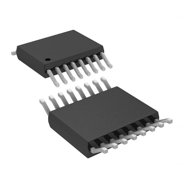
- Part No.:
- LTC2992HMS#PBF
- Manufacturer:
- Analog Devices Inc.
- Category:
- Power Supply Controllers, Monitors
- Package:
- 16-TFSOP (0.118", 3.00mm Width)
- Datasheet:
-
 LTC2992HMS#PBF.pdf
- Description:
- IC PWR MONITOR DUAL WIDE 16MSOP
- Quantity:
- Payment:

- Shipping:

Inventory:1,928
Please send an inquiry. Send us your inquiry, and we will respond immediately.
Product details
Overview
LTC2992HMS#PBF from Analog Devices is a dual wide-range rail-to-rail power monitor IC that measures current, voltage, and power of two independent supplies (0V–100V common-mode), featuring 12-bit ADCs with ±0.3% total unadjusted error, integrated shunt regulator for >100V supplies, and I²C interface with split SDAI/SDAO pins for opto-isolation support - deployed in telecom rectifier monitoring and industrial 48V DC distribution systems.
For engineers reviewing the LTC2992HMS#PBF datasheet, LTC2992HMS#PBF pinout, LTC2992HMS#PBF application, or LTC2992HMS#PBF equivalent, key selection criteria include its dual-supply 0V–100V measurement range, 16-lead MSOP package with –40°C to +125°C operation, programmable alert thresholds, minimum/maximum value storage, and simultaneous current/voltage/power computation without host CPU polling.
Technical Context
The LTC2992HMS#PBF integrates three delta-sigma ADCs: two dedicated 12-bit current-sense ADCs (full-scale ΔSENSE = 51.2 mV) and one 12-bit voltage ADC (full-scale 102.4 V on SENSE+ inputs, 2.048 V on GPIO inputs). It supports continuous scan and snapshot modes, stores min/max values per channel, and computes real-time power (P = V × I) and total system consumption (ITOTAL, PTOTAL) via on-chip digital multiplication.
Its flexible power architecture allows direct operation from 2.7V–100V VDD, internal 5V LDO regulation at INTVCC (up to 10 mA), or shunt-regulated 6.2V mode for >100V supplies. The I²C interface includes separate SDAI (input) and SDAO (output) pins, enabling galvanic isolation without external logic inversion - unlike the LTC2992-1 variant which provides inverted SDAO.
Key Specifications
| Parameter | Value and Actual Design Meaning |
|---|---|
| Supply Range | VDD = 2.7V to 100V; enables direct monitoring of 12V, 24V, 48V, and 96V industrial/telecom rails without external regulators |
| Input Common-Mode Range | 0V to 100V on SENSE1+/SENSE2+; supports high-side and low-side current sensing across full supply range |
| ADC Resolution & Accuracy | 12-bit mode with ±0.3% TUE on GPIO inputs; ensures <±0.6 mV absolute error for 2.048V full-scale auxiliary measurements |
| Current Sense Full-Scale | 51.2 mV differential input; compatible with standard 10 mΩ shunts for 5.12 A full-scale current measurement |
| Power Computation | On-chip digital multiplier calculates P1 = V1 × I1 and P2 = V2 × I2; outputs total power (PTOTAL = P1 + P2) with LSB truncation and left-shift correction |
| Operating Temperature | –40°C to +125°C (H-grade); qualified for under-hood automotive, base station power shelves, and harsh industrial environments |
| I²C Interface | Standard-mode (400 kHz max), split SDAI/SDAO pins; eliminates need for external bus buffers in isolated topologies |
Pinout & Package
Package: 16-lead plastic MSOP (4.0 mm × 3.0 mm × 1.1 mm), exposed pad optional for thermal enhancement. Pin count and physical layout match industry-standard MSOP-16 footprint.
| Pin/Terminal | Circuit Role | Design Meaning |
|---|---|---|
| SENSE1+, SENSE2+ | High-side supply voltage and current sense input | Accepts 0V–100V common-mode; connects directly to monitored rail for voltage measurement and feeds current-sense amplifier |
| SENSE1–, SENSE2– | Current sense differential input | Receives shunt resistor low-side node; full-scale ΔV = 51.2 mV enables accurate low-resistance (<10 mΩ) current sensing |
| VDD | Main high-voltage supply input | Powers internal LDO (INTVCC = 5V) when ≥8V; supports direct connection to 48V telecom or 96V battery systems |
| INTVCC | Internal regulated supply output/input | Provides 5V/10 mA for external circuitry or accepts 2.7V–5.8V external supply; includes UVLO at 2.5V |
| SCL, SDAI, SDAO | I²C clock and bidirectional data interface | Split SDAI (input) and SDAO (output) allow opto-isolator placement without level-shifting or inversion logic |
| GPIO1–GPIO4 | Configurable general-purpose I/O | Each supports ADC input (2.048V FS), open-drain output, or logic input; GPIO3 = DATAREADY, GPIO4 = ALERT |
| ADR0, ADR1 | I²C device address configuration | Three-state inputs (INTVCC/GND/open) set one of nine unique addresses - avoids bus conflicts in multi-device systems |
Key Features
| Feature | Design Value |
|---|---|
| Dual independent power monitoring | Simultaneous real-time calculation of current, voltage, and power for two supplies - no software overhead for cross-channel correlation |
| Programmable alert thresholds | Per-channel over/under-voltage, over-current, and over-power limits with latched or pulsed ALERT output (GPIO4) reduce host polling frequency |
| Min/Max value storage | On-chip registers retain historical extremes for all six ADC channels (I1, I2, V1, V2, GPIO1–4), enabling trend analysis without external memory |
| Flexible power architecture | Operates from single 2.7V–100V rail, external 2.7V–5.8V supply, or shunt-regulated >100V topology - simplifies BOM across diverse voltage domains |
| Opto-isolation ready I²C | Separated SDAI (input) and SDAO (output) pins eliminate need for external inverters or bus buffers in isolated communication links |
Applications
| Telecom Rectifier Monitoring | Industrial 48V DC Distribution |
|---|---|
Use Scenario: Real-time supervision of dual-output -48V telecom rectifiers feeding redundant load banks in central office power systems. IC Role / Device Role / Timing Role: LTC2992HMS#PBF measures output current, voltage, and power per rectifier channel while computing total system load and flagging overcurrent events via ALERT. Use Value: Enables predictive maintenance by logging min/max current drift over time and detecting early-stage rectifier imbalance before failure. | Use Scenario: Monitoring input and output rails of industrial DC-DC converters in programmable logic controller (PLC) backplanes. IC Role / Device Role / Timing Role: LTC2992HMS#PBF senses high-side current on 48V input and 24V output rails, calculates efficiency (POUT/PIN), and triggers shutdown on overtemperature-induced overcurrent. Use Value: Eliminates need for discrete current shunts, op-amps, and microcontroller ADC resources - reducing component count by ≥7 parts per rail. |
| Automotive 12V/48V Dual-Battery Systems | Server Rack Power Shelf Management |
Use Scenario: Simultaneous monitoring of legacy 12V starter battery and new 48V mild-hybrid traction battery in next-gen EV architectures. IC Role / Device Role / Timing Role: LTC2992HMS#PBF measures charge/discharge current and voltage on both batteries, computes net power flow, and asserts DATAREADY upon threshold breach. Use Value: Supports ASIL-B functional safety requirements via built-in min/max history and fault logging - no external EEPROM required for event traceability. | Use Scenario: Per-blade power telemetry in hyperscale server racks where 12V and 54V intermediate bus converters feed compute modules. IC Role / Device Role / Timing Role: LTC2992HMS#PBF monitors input current/voltage of dual power shelves and reports total rack consumption via I²C to BMC firmware. Use Value: Provides hardware-enforced power capping: ALERT signal halts blade provisioning when PTOTAL exceeds thermal envelope, preventing thermal runaway. |
Equivalent & Alternatives
The following parts are listed as comparable options for similar dual-supply power monitoring applications.
| Alternative Part | Technical Difference | Application Difference | Selection Advice |
|---|---|---|---|
| INA226AIDGST | Single-channel, 16-bit current/voltage monitor; no integrated power calculation or dual-rail support; 0V–36V common-mode only | Requires two devices + MCU for dual-rail monitoring; lacks min/max storage and ALERT programmability | Select when cost sensitivity outweighs integration needs and supply range ≤36V |
| LTC2991IMS#PBF | Single-supply version of same family; identical 0V–100V range, 12-bit ADCs, and MSOP-16 package but monitors only one rail | No dual-rail power summation or cross-channel correlation; half the GPIO count and no PTOTAL register | Select when system requires only one monitored rail but demands identical H-grade temp range and isolation-ready I²C |
Compared with INA226AIDGST and LTC2991IMS#PBF, the LTC2992HMS#PBF uniquely delivers dual-rail power computation, on-chip min/max history, and opto-isolation-ready I²C in a single H-grade MSOP package - reducing system-level complexity for 48V+ infrastructure where space, thermal margin, and isolation are critical.
Availability
LTC2992HMS#PBF is available at Aetrix Electronics and suitable for telecom rectifier monitoring, industrial 48V DC distribution, and automotive dual-battery systems requiring stable component supply across extended temperature ranges and long production lifecycles.
Supply support for LTC2992HMS#PBF includes scheduled delivery planning, volume procurement assistance, BOM continuity management, traceable sourcing, and lifecycle availability coordination for OEM customers, industrial embedded developers, connected-device designers, and electronics production programs.
Manufacturer
Analog Devices, Inc. is a global leader in high-performance analog, mixed-signal, and digital signal processing semiconductors, serving precision instrumentation, industrial automation, communications, and automotive markets.
The LTC2992 product line delivers highly integrated, wide-range power monitoring solutions designed specifically for high-reliability infrastructure applications where supply voltages exceed 36V and ambient temperatures reach +125°C.
FAQ
What is the maximum common-mode voltage the LTC2992HMS#PBF can measure on SENSE1+ and SENSE2+ inputs?
The LTC2992HMS#PBF supports a 0V to 100V input common-mode range on both SENSE1+ and SENSE2+ pins. This allows direct high-side or low-side monitoring of industrial 48V, telecom -48V, and automotive 12V/48V rails without external level-shifting circuitry. Absolute maximum rating extends to 100V, and operation remains specified across the full –40°C to +125°C temperature range for the H-grade device.
Does the LTC2992HMS#PBF require external calibration for accurate current measurements?
The LTC2992HMS#PBF performs automatic offset calibration of its current-sense amplifiers during each conversion cycle by default. This eliminates the need for external calibration components or factory-trimmed references. Users may reduce calibration frequency via the CTRLA[7] bit to extend conversion throughput, though initial calibration at power-up remains mandatory. No external zero-current adjustment is required for production use.
Can the LTC2992HMS#PBF operate from a 3.3V supply, or does it require a higher VDD?
The LTC2992HMS#PBF can operate from a 3.3V supply applied to the VDD pin, but only if INTVCC is externally powered with 2.7V–5.8V. When VDD < 8V, the internal LDO is disabled and INTVCC must be supplied externally. For standalone operation, VDD must be ≥8V to enable the 5V LDO output. The datasheet specifies VDD = 3V minimum only when INTVCC is externally driven.
How does the LTC2992HMS#PBF handle power calculation when using different shunt resistors on SENSE1 and SENSE2?
The LTC2992HMS#PBF computes power as P = V × I, where I is derived from ΔSENSE voltage and known shunt resistance (RSHUNT). Since the device reports raw ADC codes and full-scale values (51.2 mV), users must apply RSHUNT-specific scaling in firmware. The on-chip multiplier uses uncalibrated digital values; therefore, mismatched shunts require post-processing to maintain accuracy - the LTC2992HMS#PBF itself does not store or compensate for differing RSHUNT values.
Is the LTC2992HMS#PBF pin-compatible with the LTC2992HDE#PBF?
Yes, the LTC2992HMS#PBF (MSOP-16) and LTC2992HDE#PBF (DFN-16) share identical pin functions and electrical specifications, including –40°C to +125°C operation. However, they differ in package type (MSOP vs. 4mm × 3mm DFN), thermal performance (θJA = 120°C/W vs. 43°C/W), and PCB layout requirements. No schematic changes are needed, but thermal vias and copper area must be adapted for the DFN variant.
LTC2992HMS#PBF Specifications
- Product attributes
- Attribute value
- Manufacturer:
- Analog Devices Inc.
- Series:
- -
- Package/Case:
- 16-TFSOP (0.118", 3.00mm Width)
- Packaging:
- Tube
- Product Status:
- Active
- Programmable:
- Not Verified
- Applications:
- Telecommunications
- Voltage - Input:
- 0V ~ 100V
- Voltage - Supply:
- 3V ~ 100V
- Current - Supply:
- 1.6 mA
- Operating Temperature:
- -40°C ~ 125°C (TJ)
- Grade:
- -
- Qualification:
- -
- Mounting Type:
- Surface Mount
- Supplier Device Package:
- 16-MSOP
LTC2992HMS#PBF FAQ
1.How can I place an order for LTC2992HMS#PBF through Aetrix?
Please submit a Request for Quotation (RFQ) for LTC2992HMS#PBF on Aetrix. Our sales agent will provide a competitive quotation and guide you through the order confirmation once you accept the terms.
2.Are the price and stock information for LTC2992HMS#PBF reliable?
The price and inventory of LTC2992HMS#PBF are updated periodically and may fluctuate due to market conditions. Stock and pricing data are typically refreshed every 24 hours. Quotation validity for LTC2992HMS#PBF is usually 5 days.
3.What payment methods are accepted for LTC2992HMS#PBF?
We accept Wire Transfer, PayPal, Credit Card, Western Union, MoneyGram, and Escrow for LTC2992HMS#PBF transactions.
Note: Certain payment methods may incur a processing fee.
4.How is shipping managed for LTC2992HMS#PBF?
LTC2992HMS#PBF orders can be shipped via leading logistics carriers, including DHL, UPS, FedEx, TNT, or Registered Mail.
Once your LTC2992HMS#PBF order is processed, you will receive an email with the shipment details and tracking number.
Note: Tracking information may take up to 24 hours to appear. Express delivery typically takes 3–5 business days.
5.How can I obtain technical support or documentation for LTC2992HMS#PBF?
For technical support, including LTC2992HMS#PBF datasheets, pinout diagrams, or application guidance, please contact our engineering support team. They can provide detailed documentation and assistance for your LTC2992HMS#PBF requirements.
6.How does Aetrix verify that LTC2992HMS#PBF is sourced from the original manufacturer or authorized distributors?
All LTC2992HMS#PBF products on Aetrix are procured from qualified distributors and authorized channels. Our dedicated quality assurance team conducts strict verification, including traceability checks and, if necessary, third-party testing. This ensures that LTC2992HMS#PBF meets industry standards.
7.What is the process for return or replacement of LTC2992HMS#PBF?
All LTC2992HMS#PBF units undergo pre-shipment inspection (PSI). If there is an issue with LTC2992HMS#PBF, returns or replacements are accepted under the following conditions:
1.Quantity discrepancies, incorrect items, or visible external defects (such as breakage or corrosion), acknowledged by Aetrix.
2.The issue is reported within 90 days of delivery.
3.The LTC2992HMS#PBF part is unused and in its original packaging.
Return procedure for LTC2992HMS#PBF:
1.Submit a request within 90 days.
2.Obtain a Return Material Authorization (RMA) from Aetrix.
LTC2992HMS#PBF Tags

-
UC3845AD8TR
Texas Instruments
-
UC2843AD8TR
Texas Instruments

-
LM3880MFX-1AE/NOPB
Texas Instruments
-
LM3880MFX-1AA/NOPB
Texas Instruments

-
INA234AIYBJR
Texas Instruments

-
INA700AYWFR
Texas Instruments
-
LM3880MF-1AE/NOPB
Texas Instruments
-
LM3880MF-1AA/NOPB
Texas Instruments

-
LM3881MM/NOPB
Texas Instruments
-
UCC2802DTR
Texas Instruments

-
NCP4305DMTTWG
onsemi

-
INA237AIDGSR
Texas Instruments
Tech Hub

A practical engineering guide to 3.3V and 5V logic compatibility, input thresholds, resistor dividers, translator ICs, MOSFET level shifting, I2C pull-ups, timing limits and power-sequencing risks.

The 74HC595 uses push-pull logic outputs, while the TPIC6B595 uses 50 V open-drain DMOS sinks for higher-power loads. This guide compares timing, current limits, 3.3 V interfacing, load wiring, thermal…

The 74HC595 converts serial data into eight stable parallel outputs. This guide covers pin functions, shift and storage timing, OE and MR behavior, drive-current limits, cascading, voltage compatibilit…

A technical comparison of level-sensitive latches and edge-triggered flip-flops, covering timing windows, setup and hold limits, master–slave operation, time borrowing, race-through, HDL inference and…

A D latch stores one bit while Enable controls when data can pass. This reference covers gate-level operation, truth tables, transparency, setup and hold timing, LE versus OE, common ICs and practical …

An SR latch stores one bit through cross-coupled feedback. This engineering reference covers NOR and NAND implementations, truth tables, forbidden-state recovery, gated operation, switch debouncing, fa…

Latch circuits retain one bit through feedback. This technical reference covers SR and D latches, truth tables, transparency, timing limits, latch-versus-flip-flop behavior, applications and common log…

An engineering guide to LED driver operation, constant-current and constant-voltage outputs, linear and switching topologies, dimming, IC selection, calculations, replacement compatibility, and fault c…

Operational amplifier guide covering op amp basics, feedback, ideal vs real op amps, common configurations, buffer circuits, offset, bias current, gain-bandwidth, slew rate, rail-to-rail limits and sel…

Jumper cables guide covering safe connection order, red and black clamp placement, final ground connection, cable gauge, length, clamp quality, copper vs CCA cables, jump starter comparison and battery…


