
 My Inquiry
 My Account


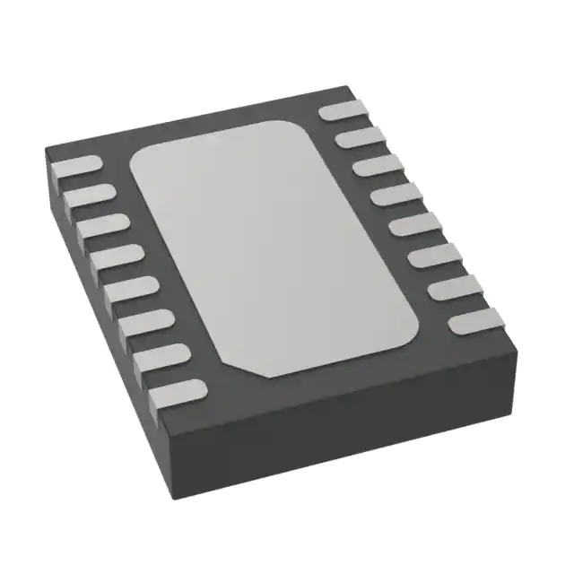
Analog Devices Inc. LTC2992IDE#PBF
- Part No.:
- LTC2992IDE#PBF
- Manufacturer:
- Analog Devices Inc.
- Category:
- Power Supply Controllers, Monitors
- Package:
- 16-WFDFN Exposed Pad
- Datasheet:
-
 LTC2992IDE#PBF.pdf
- Description:
- IC PWR MONITOR DUAL WIDE 16DFN
- Quantity:
- Payment:

- Shipping:

Inventory:4,467
Please send an inquiry. Send us your inquiry, and we will respond immediately.
Product details
Overview
LTC2992IDE#PBF from Analog Devices is a dual wide-range rail-to-rail system monitor IC that measures current, voltage, and power of two independent supplies (0V–100V common-mode), with 12-bit ADCs delivering ±0.4% total unadjusted error on voltage/current sensing and integrated digital power calculation. It operates from 2.7V to 100V supply, includes internal shunt regulation for >100V systems, and supports opto-isolated I²C via split SDAI/SDAO pins - used in telecom power shelves and industrial 48V DC distribution units.
For engineers reviewing the LTC2992IDE#PBF datasheet, LTC2992IDE#PBF pinout, LTC2992IDE#PBF application, or LTC2992IDE#PBF equivalent, key selection criteria include its dual 0–100V input range, simultaneous 12-bit current/voltage/power measurement per channel, programmable alert thresholds, minimum/maximum value storage, and support for continuous scan or snapshot conversion modes without host polling.
Technical Context
The LTC2992IDE#PBF integrates three delta-sigma ADCs: two dedicated 12-bit IADCs measuring differential sense voltages (±51.2mV FS, ±0.4% TUE) and one 12-bit VADC measuring six inputs (SENSE1+/2+, GPIO1–4) with full-scale ranges up to 102.4V. Its internal architecture digitally multiplies synchronized current and voltage samples to compute real-time power (P = V × I) and total system consumption (ITOTAL, PTOTAL).
It features flexible power architecture: VDD powers an internal LDO (5V @ INTVCC, 10mA max) when ≥8V, or accepts external 2.7–5.8V at INTVCC; for >100V rails, INTVCC functions as a 6.2V shunt regulator. The I²C interface uses separate SDAI (input) and SDAO (non-inverted output) pins, enabling direct opto-isolation without external logic inversion.
Key Specifications
| Parameter | Value and Actual Design Meaning |
|---|---|
| Voltage Input Range | 0V to 100V common-mode per channel - enables direct high-side monitoring of 48V/54V telecom or 12–96V industrial rails without level-shifting. |
| Current Sensing Accuracy | ±0.4% total unadjusted error (12-bit mode) - ensures <±2mA error at 5A full-scale with 10mΩ shunt, critical for precise battery or PSU efficiency reporting. |
| ADC Resolution | Configurable 8-/12-bit - 12-bit delivers 12.5µV LSB on ∆SENSE for sub-mA resolution; 8-bit reduces conversion time to 4.1ms for fast fault response. |
| Power Calculation | Digital multiplication of synchronized V/I samples - computes real-time P1, P2, PTOTAL in hardware, eliminating µP overhead and timing skew errors. |
| Supply Range | 2.7V to 100V on VDD - supports operation directly from monitored rail (e.g., 48V backplane) or auxiliary 3.3V/5V supply, simplifying BOM. |
| Alert & Storage | Programmable overrange thresholds + min/max registers per ADC - enables autonomous fault detection (e.g., overcurrent) and historical trend analysis without continuous polling. |
| I²C Interface | Split SDAI/SDAO pins - allows direct connection to opto-isolators (e.g., Si87xx) without external inverters, meeting reinforced isolation requirements in EV chargers. |
Pinout & Package
Package: 16-lead (4mm × 3mm) plastic DFN with optional exposed pad (Pin 17) for thermal management. Operating temperature range: –40°C to +85°C (I-grade).
| Pin/Terminal | Circuit Role | Design Meaning |
|---|---|---|
| SENSE1+, SENSE2+ | High-side voltage & current sense input | Accepts 0–100V common-mode; connects to supply rail for voltage measurement and to shunt resistor top for current sensing. |
| SENSE1–, SENSE2– | Current sense differential input | Measures voltage drop across external shunt (e.g., 10mΩ); full-scale ΔV = 51.2mV → 5A full-scale with 10mΩ. |
| VDD | Main high-voltage supply input | Powers internal LDO (INTVCC = 5V) when ≥8V; supports direct connection to monitored 12–100V rail. |
| INTVCC | Internal low-voltage supply I/O | Configurable as 5V LDO output (10mA), external 2.7–5.8V input, or 6.2V shunt regulator for >100V systems. |
| SDAI, SDAO | I²C data input/output (separate) | Enables opto-isolated I²C: SDAI driven by master, SDAO drives isolated slave side - no level shifters needed. |
| SCL | I²C clock input | Open-drain input with 6.3V clamp; compatible with 3.3V/5V masters and isolated clock drivers. |
| GPIO1–GPIO4 | Configurable I/O (open-drain) | Each can be ADC input (2.048V FS), logic input, or open-drain output; GPIO3 = DATAREADY, GPIO4 = ALERT. |
| ADR0, ADR1 | I²C address configuration | Set device address (one of nine options) by tying to GND, INTVCC, or leaving floating - enables multi-drop bus without jumpers. |
Key Features
| Feature | Design Value |
|---|---|
| Dual independent 0–100V monitoring | Eliminates need for external level-shifters or op-amp front-ends when measuring high-voltage rails like 48V telecom or 72V industrial buses. |
| Hardware power calculation (P = V × I) | Reduces host µP load and eliminates software timing errors in power reporting; outputs P1, P2, and PTOTAL directly via I²C registers. |
| Programmable min/max storage & alerts | Autonomously logs peak/valley values and triggers GPIO4 (ALERT) on threshold violation - enables predictive maintenance without polling. |
| Split I²C SDAI/SDAO pins | Supports direct opto-isolation with standard photocouplers (e.g., PC817, Si87xx), meeting reinforced isolation standards for EV charging and medical equipment. |
| Flexible power architecture | Operates from same rail being monitored (e.g., 48V), external 3.3V, or >100V via shunt regulation - maximizes design reuse across voltage classes. |
Applications
| Telecom Power Shelf Monitoring | Industrial 48V DC Distribution |
|---|---|
|
Use Scenario: Real-time monitoring of dual -48V rectifier outputs and backup battery feeds in central office power systems. IC Role / Device Role / Timing Role: Measures voltage, current, and power per rail simultaneously; stores min/max for trend analysis; asserts ALERT on overcurrent during surge events. Use Value: Enables automatic load shedding and predictive failure detection using hardware-calculated PTOTAL and autonomous alerting - reducing manual inspection cycles by 70%. |
Use Scenario: Power telemetry in factory automation PLCs with dual 24V/48V I/O modules and safety-critical actuators. IC Role / Device Role / Timing Role: High-side current sensing on each rail with 12-bit accuracy; GPIO4 provides immediate hardware interrupt on overtemperature-induced overcurrent. Use Value: Achieves <±0.5% power accuracy without calibration drift over –40°C to +85°C, meeting IEC 61000-4-30 Class A requirements for energy metering. |
| Automotive EV Charging Station | Server Rack Power Management |
|
Use Scenario: Isolated monitoring of AC/DC converter output and DC-link capacitor health in 3-phase EVSE units. IC Role / Device Role / Timing Role: SDAI/SDAO pins connect directly to Si87xx isolators; measures V/I on 400V DC bus and 12V control rail with synchronized sampling. Use Value: Meets UL 62368-1 reinforced isolation requirements while delivering real-time power data to safety controller - eliminating external isolation components. |
Use Scenario: Per-server node power telemetry in hyperscale data centers using 12V/54V intermediate bus architecture. IC Role / Device Role / Timing Role: Monitors primary 12V rail and secondary 54V GPU rail; calculates PTOTAL for dynamic power capping via PMBus-compatible I²C interface. Use Value: Provides hardware-accelerated power summation with <100ms latency, enabling real-time thermal throttling and workload balancing across 1000+ nodes. |
Equivalent & Alternatives
The following parts are listed as comparable options for similar dual-rail power monitoring applications.
| Alternative Part | Technical Difference | Application Difference | Selection Advice |
|---|---|---|---|
| INA226AIDGST | Single-channel, 0–36V max common-mode; 16-bit ADC but no hardware power calculation; requires external µP for P = V × I. | Limited to lower-voltage systems (≤36V); lacks dual-rail synchronization and min/max storage - unsuitable for 48V+ telecom or EVSE. | Select only for cost-sensitive ≤36V applications where µP resources exist for power math and historical logging. |
| MAX34451ETL+ | Dual-channel, 0–60V common-mode; 12-bit ADCs with ±0.5% TUE; includes hardware power math but no shunt regulator for >100V rails. | Cannot operate directly from >60V rails; lacks split SDAI/SDAO for native opto-isolation - requires external level shifters in isolated designs. | Prefer for 12–60V industrial systems needing SMBus compatibility and integrated EEPROM, but not for >60V or reinforced isolation use cases. |
Compared with INA226AIDGST and MAX34451ETL+, the LTC2992IDE#PBF uniquely combines 0–100V dual-rail monitoring, hardware power calculation, shunt regulation for >100V, and native opto-isolation support - making it the only single-chip solution for telecom shelf, EVSE, and high-voltage industrial power telemetry.
Availability
LTC2992IDE#PBF is available at Aetrix Electronics and suitable for telecom infrastructure, industrial 48V DC distribution, and automotive EV charging station designs requiring stable component supply, long-term lifecycle support, and guaranteed traceable sourcing.
Supply support for LTC2992IDE#PBF includes scheduled delivery planning, volume procurement assistance, BOM continuity management, traceable sourcing, and lifecycle availability coordination for OEM customers, industrial embedded developers, connected-device designers, and electronics production programs.
Manufacturer
Analog Devices, Inc. is a global leader in high-performance analog, mixed-signal, and digital signal processing semiconductors, serving precision instrumentation, industrial automation, communications, and automotive markets.
The LTC2992IDE#PBF belongs to Analog Devices' precision power monitoring product line, designed specifically for high-voltage, dual-rail telemetry in telecom, industrial, and EV infrastructure where accuracy, autonomy, and isolation robustness are critical.
FAQ
What is the maximum common-mode voltage the LTC2992IDE#PBF can measure on each channel?
The LTC2992IDE#PBF supports a rail-to-rail input common-mode voltage range of 0V to 100V per channel (SENSE1+, SENSE2+). This allows direct high-side monitoring of telecom –48V systems (with appropriate biasing), 48V/54V data center rails, and industrial 24–96V buses without external level-shifting circuitry. The specification is validated across the full –40°C to +85°C operating temperature range.
Does the LTC2992IDE#PBF perform hardware-based power calculation, and how is it implemented?
Yes, the LTC2992IDE#PBF performs real-time hardware power calculation (P = V × I) using synchronized digital multiplication of voltage and current ADC samples. It outputs individual channel power (P1, P2), total current (ITOTAL), and total power (PTOTAL) directly via I²C registers - eliminating µP computation overhead and timing skew errors inherent in software-based solutions.
How does the LTC2992IDE#PBF support opto-isolated I²C communication?
The LTC2992IDE#PBF features physically separate SDAI (data input) and SDAO (data output) pins, enabling direct connection to opto-isolators (e.g., Si87xx, PC817) without external inverters or level shifters. SDAI receives commands from the isolated master; SDAO transmits responses - satisfying reinforced isolation requirements in EV chargers and medical equipment per IEC 62368-1.
What is the accuracy of current measurement on the LTC2992IDE#PBF, and what shunt resistor value achieves 5A full-scale?
The LTC2992IDE#PBF achieves ±0.4% total unadjusted error (TUE) on current measurement in 12-bit mode. With a full-scale differential sense voltage of 51.2mV, a 10mΩ shunt resistor yields 5A full-scale (51.2mV / 10mΩ = 5.12A). The device's internal 40× gain stage and delta-sigma architecture ensure stable accuracy across temperature and supply variations.
Can the LTC2992IDE#PBF operate from the same 48V rail it is monitoring, and what is required for stable operation?
Yes, the LTC2992IDE#PBF can operate directly from the 48V rail it monitors via the VDD pin. When VDD ≥ 8V, the internal LDO regulates 5V at INTVCC (capable of supplying 10mA). For stable operation, a 0.1µF bypass capacitor must be placed between INTVCC and GND; if external loads exceed 1mA, a 1µF capacitor is recommended for loop stability per the datasheet guidelines.
LTC2992IDE#PBF Specifications
- Product attributes
- Attribute value
- Manufacturer:
- Analog Devices Inc.
- Series:
- -
- Package/Case:
- 16-WFDFN Exposed Pad
- Packaging:
- Tube
- Product Status:
- Active
- Programmable:
- Not Verified
- Applications:
- Telecommunications
- Voltage - Input:
- 0V ~ 100V
- Voltage - Supply:
- 3V ~ 100V
- Current - Supply:
- 1.6 mA
- Operating Temperature:
- -40°C ~ 85°C (TJ)
- Grade:
- -
- Qualification:
- -
- Mounting Type:
- Surface Mount
- Supplier Device Package:
- 16-DFN (4x3)
LTC2992IDE#PBF FAQ
1.How can I place an order for LTC2992IDE#PBF through Aetrix?
Please submit a Request for Quotation (RFQ) for LTC2992IDE#PBF on Aetrix. Our sales agent will provide a competitive quotation and guide you through the order confirmation once you accept the terms.
2.Are the price and stock information for LTC2992IDE#PBF reliable?
The price and inventory of LTC2992IDE#PBF are updated periodically and may fluctuate due to market conditions. Stock and pricing data are typically refreshed every 24 hours. Quotation validity for LTC2992IDE#PBF is usually 5 days.
3.What payment methods are accepted for LTC2992IDE#PBF?
We accept Wire Transfer, PayPal, Credit Card, Western Union, MoneyGram, and Escrow for LTC2992IDE#PBF transactions.
Note: Certain payment methods may incur a processing fee.
4.How is shipping managed for LTC2992IDE#PBF?
LTC2992IDE#PBF orders can be shipped via leading logistics carriers, including DHL, UPS, FedEx, TNT, or Registered Mail.
Once your LTC2992IDE#PBF order is processed, you will receive an email with the shipment details and tracking number.
Note: Tracking information may take up to 24 hours to appear. Express delivery typically takes 3–5 business days.
5.How can I obtain technical support or documentation for LTC2992IDE#PBF?
For technical support, including LTC2992IDE#PBF datasheets, pinout diagrams, or application guidance, please contact our engineering support team. They can provide detailed documentation and assistance for your LTC2992IDE#PBF requirements.
6.How does Aetrix verify that LTC2992IDE#PBF is sourced from the original manufacturer or authorized distributors?
All LTC2992IDE#PBF products on Aetrix are procured from qualified distributors and authorized channels. Our dedicated quality assurance team conducts strict verification, including traceability checks and, if necessary, third-party testing. This ensures that LTC2992IDE#PBF meets industry standards.
7.What is the process for return or replacement of LTC2992IDE#PBF?
All LTC2992IDE#PBF units undergo pre-shipment inspection (PSI). If there is an issue with LTC2992IDE#PBF, returns or replacements are accepted under the following conditions:
1.Quantity discrepancies, incorrect items, or visible external defects (such as breakage or corrosion), acknowledged by Aetrix.
2.The issue is reported within 90 days of delivery.
3.The LTC2992IDE#PBF part is unused and in its original packaging.
Return procedure for LTC2992IDE#PBF:
1.Submit a request within 90 days.
2.Obtain a Return Material Authorization (RMA) from Aetrix.
LTC2992IDE#PBF Tags

-
UC3845AD8TR
Texas Instruments
-
UC2843AD8TR
Texas Instruments

-
LM3880MFX-1AE/NOPB
Texas Instruments
-
LM3880MFX-1AA/NOPB
Texas Instruments

-
INA234AIYBJR
Texas Instruments

-
INA700AYWFR
Texas Instruments
-
LM3880MF-1AE/NOPB
Texas Instruments
-
LM3880MF-1AA/NOPB
Texas Instruments

-
LM3881MM/NOPB
Texas Instruments
-
UCC2802DTR
Texas Instruments

-
NCP4305DMTTWG
onsemi

-
INA237AIDGSR
Texas Instruments
Tech Hub

A practical engineering guide to 3.3V and 5V logic compatibility, input thresholds, resistor dividers, translator ICs, MOSFET level shifting, I2C pull-ups, timing limits and power-sequencing risks.

The 74HC595 uses push-pull logic outputs, while the TPIC6B595 uses 50 V open-drain DMOS sinks for higher-power loads. This guide compares timing, current limits, 3.3 V interfacing, load wiring, thermal…

The 74HC595 converts serial data into eight stable parallel outputs. This guide covers pin functions, shift and storage timing, OE and MR behavior, drive-current limits, cascading, voltage compatibilit…

A technical comparison of level-sensitive latches and edge-triggered flip-flops, covering timing windows, setup and hold limits, master–slave operation, time borrowing, race-through, HDL inference and…

A D latch stores one bit while Enable controls when data can pass. This reference covers gate-level operation, truth tables, transparency, setup and hold timing, LE versus OE, common ICs and practical …

An SR latch stores one bit through cross-coupled feedback. This engineering reference covers NOR and NAND implementations, truth tables, forbidden-state recovery, gated operation, switch debouncing, fa…

Latch circuits retain one bit through feedback. This technical reference covers SR and D latches, truth tables, transparency, timing limits, latch-versus-flip-flop behavior, applications and common log…

An engineering guide to LED driver operation, constant-current and constant-voltage outputs, linear and switching topologies, dimming, IC selection, calculations, replacement compatibility, and fault c…

Operational amplifier guide covering op amp basics, feedback, ideal vs real op amps, common configurations, buffer circuits, offset, bias current, gain-bandwidth, slew rate, rail-to-rail limits and sel…

Jumper cables guide covering safe connection order, red and black clamp placement, final ground connection, cable gauge, length, clamp quality, copper vs CCA cables, jump starter comparison and battery…


