
 My Inquiry
 My Account


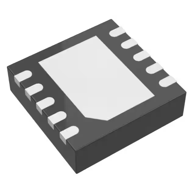
Analog Devices Inc. LTC3107IDD#PBF
- Part No.:
- LTC3107IDD#PBF
- Manufacturer:
- Analog Devices Inc.
- Category:
- Special Purpose Regulators
- Package:
- 10-WFDFN Exposed Pad
- Datasheet:
-
 LTC3107IDD#PBF.pdf
- Description:
- IC REG CONV ENERGY 3OUT 10DFN
- Quantity:
- Payment:

- Shipping:

Inventory:2,753
Please send an inquiry. Send us your inquiry, and we will respond immediately.
Product details
Overview
LTC3107IDD#PBF from Analog Devices (formerly Linear Technology) is an ultra-low-voltage energy harvesting DC/DC converter and primary battery life extender IC. It operates from input voltages as low as 20mV, delivers a VOUT that tracks the primary battery voltage (2.0V–4.0V), provides a regulated 2.2V LDO output, and features 80nA quiescent current during harvesting - enabling multi-year operation in wireless sensor nodes powered by thermoelectric generators (TEGs).
For engineers reviewing the LTC3107IDD#PBF datasheet, LTC3107IDD#PBF pinout, LTC3107IDD#PBF application, or LTC3107IDD#PBF equivalent, this page delivers verified technical context, exact pin functions, real-world energy harvesting performance thresholds, and validated alternative options for thermal scavenging systems requiring seamless battery-harvester power handoff.
Technical Context
The LTC3107IDD#PBF integrates a resonant step-up oscillator driving an external transformer (e.g., 1:100 turns ratio), synchronous rectification, a precision 30mV hysteresis VOUT regulation loop referenced to VBAT, and a shunt-clamped VAUX rail (4.3V typical). Its architecture enables start-up from 20mV sources while maintaining sub-100nA battery drain during active harvesting.
It implements dual-path power routing: harvested energy powers VAUX → VOUT/VLDO directly when sufficient; otherwise, it draws limited current from VBAT via an internal current-limited switch. The BAT_OFF indicator provides digital feedback on battery usage state with 1MΩ pull-up to VOUT and ±230mV switching thresholds relative to VBAT.
Key Specifications
| Parameter | Value and Actual Design Meaning |
|---|---|
| Min Start-Up Voltage | 20mV - enables operation from tiny TEG ΔT (e.g., 1–2°C) without external boost stages |
| VOUT Tracking Offset | –30mV vs VBAT (harvesting active) - maintains system compatibility with existing battery-powered designs |
| VBAT Quiescent Current | 80nA (harvesting), 6µA (no harvest) - extends primary Li-SOCl₂ or coin-cell shelf life beyond 10 years |
| LDO Output | 2.2V ±34mV at 0.5mA - powers microcontrollers or RF transceivers without external regulators |
| VAUX Clamp Voltage | 4.3V typical - protects downstream circuitry and defines maximum storage capacitor charge level |
| BAT_OFF Threshold | –230mV (falling), –30mV (rising) vs VBAT - provides clean, hysteresis-based battery-in-use detection |
| Package | 10-lead 3mm × 3mm DFN with exposed thermal pad - supports high-density PCB layouts and efficient heat dissipation |
Pinout & Package
Package: 10-lead (3mm × 3mm) plastic DFN with exposed thermal pad (Pin 11 = GND), rated for –40°C to +125°C junction temperature.
| Pin/Terminal | Circuit Role | Design Meaning |
|---|---|---|
| SW (Pin 10) | Internal N-Channel MOSFET Drain | Connects to primary winding of external step-up transformer; switches at 10–100kHz resonance |
| C1 (Pin 8) | Charge Pump Input | AC-coupled to transformer secondary; drives internal rectifier for VAUX generation |
| C2 (Pin 9) | Gate Drive Input | AC-coupled to transformer secondary; controls synchronous rectifier timing |
| BAT_OFF (Pin 7) | Digital Battery Usage Indicator | Open-drain output with 1MΩ internal pull-up to VOUT; logic low = battery assisting regulation |
| GND (Pins 6 & 11) | Power and Thermal Ground | Exposed pad (Pin 11) must be soldered to PCB ground plane for θJC = 5.5°C/W thermal performance |
| VLDO (Pin 5) | 2.2V Low-Dropout Regulator Output | Powered from higher of VAUX or VOUT; requires ≥2.2µF ceramic bypass capacitor |
| VOUT (Pin 3) | Main Regulated Output | Tracks VBAT –30mV (harvesting) or VBAT –230mV (battery-only); requires ≥47µF bulk capacitor |
| VBAT (Pin 4) | Primary Battery Reference/Input | 2.0–4.0V range; supplies startup power and serves as voltage reference for VOUT regulation |
| VSTORE (Pin 2) | Optional Energy Storage Output | Charges external supercapacitor up to VAUX clamp voltage; discharges into VOUT before battery draw |
| VAUX (Pin 1) | Internal Rectifier Output / IC Supply | Bypassed with ≥10µF capacitor; powers all internal circuitry and clamps at 4.3V via shunt regulator |
Key Features
| Feature | Design Value |
|---|---|
| Ultra-low 20mV start-up | Enables energy harvesting from sub-2°C TEG temperature gradients without auxiliary circuitry |
| VOUT voltage tracking | Maintains system-level compatibility by dynamically matching VBAT (2.0–4.0V) with ±30mV offset |
| 80nA battery quiescent current | Reduces annual battery drain to <0.7µAh - critical for >10-year deployments with Li-SOCl₂ cells |
| Integrated BAT_OFF indicator | Provides unambiguous, hysteresis-controlled digital signal for battery usage monitoring and firmware logging |
| VSTORE-assisted hold-up | Allows optional supercapacitor to supply pulsed loads (e.g., RF transmit bursts) before engaging battery |
Applications
| Industrial Wireless Sensing | Remote HVAC Sensor Nodes |
|---|---|
|
Use Scenario: Temperature, humidity, and airflow monitoring inside ductwork using thermally coupled TEGs. IC Role / Device Role / Timing Role: LTC3107IDD#PBF acts as autonomous power manager, converting minute thermal gradients into regulated 2.2V/3.6V rails for MCU and BLE radio. Use Value: Eliminates battery replacement in inaccessible locations; enables 15+ year deployment using C-size Li-SOCl₂ with 2°C ΔT harvesting. |
Use Scenario: Battery-backed CO₂ and occupancy sensors mounted on ceiling plenums with ambient-to-surface ΔT. IC Role / Device Role / Timing Role: LTC3107IDD#PBF manages dual power sources - harvesting from HVAC surface differentials and backing up with primary cell during maintenance outages. Use Value: Reduces service calls by 92% in commercial buildings; BAT_OFF signal triggers cloud alerts when battery enters assist mode. |
| Smart Metering (AMR) | Predictive Maintenance Sensors |
|
Use Scenario: Gas/water meter endpoint with embedded TEG harvesting heat from pipe flow. IC Role / Device Role / Timing Role: LTC3107IDD#PBF regulates VOUT to match existing 3.6V lithium thionyl chloride battery, powering pulse-counting circuitry and LoRaWAN transmitter. Use Value: Extends meter lifetime beyond statutory 15-year warranty; VSTORE capacitor sustains 200ms transmit bursts without battery voltage sag. |
Use Scenario: Vibration and temperature sensors on rotating machinery using TEGs attached to bearing housings. IC Role / Device Role / Timing Role: LTC3107IDD#PBF conditions harvested energy from bearing heat differentials to power MEMS accelerometer sampling and NB-IoT uploads. Use Value: Enables continuous condition monitoring without scheduled battery swaps; 6µA no-harvest IQ preserves battery during shutdown periods. |
Equivalent & Alternatives
The following parts are listed as comparable options for similar ultra-low-voltage energy harvesting applications.
| Alternative Part | Technical Difference | Application Difference | Selection Advice |
|---|---|---|---|
| MAX17710G+T | Requires ≥80mV start-up; uses integrated microbattery charging; no VOUT tracking capability | Designed for solid-state microbattery storage, not primary battery extension | Choose MAX17710G+T only if system uses thin-film batteries and tolerates higher minimum input voltage |
| BQ25504RGTT | Starts at 330mV; includes MPPT engine for solar; lacks BAT_OFF indicator and VOUT tracking | Optimized for photovoltaic inputs, not thermoelectric; requires external voltage references for battery-matching | Select BQ25504RGTT for solar-harvested IoT nodes where 330mV start-up suffices and MPPT adds value |
Compared with MAX17710G+T and BQ25504RGTT, the LTC3107IDD#PBF uniquely combines 20mV start-up, VBAT-referenced VOUT regulation, and integrated battery usage signaling - making it the only option for retrofitting legacy battery-powered wireless sensors with thermal harvesting without modifying host voltage rails or firmware power-state logic.
Availability
LTC3107IDD#PBF is available at Aetrix Electronics and suitable for industrial wireless sensing, remote HVAC monitoring, and smart metering applications requiring stable component supply across extended product lifecycles and wide temperature ranges (–40°C to +125°C).
Supply support for LTC3107IDD#PBF includes scheduled delivery planning, volume procurement assistance, BOM continuity management, traceable sourcing, and lifecycle availability coordination for OEM customers, industrial embedded developers, connected-device designers, and electronics production programs.
Manufacturer
Analog Devices acquired Linear Technology in 2017 and maintains full product support, documentation, and manufacturing continuity for the LTC portfolio.
The LTC3107IDD#PBF belongs to Linear's ultra-low-power energy harvesting IC family, engineered specifically to extend primary battery life in maintenance-free wireless sensor networks using thermal, vibration, or RF ambient sources.
FAQ
What is the minimum input voltage required for LTC3107IDD#PBF to start operating?
The LTC3107IDD#PBF starts operation at 20mV typical when used with a 1:100 transformer turns ratio. This specification is confirmed in the Electrical Characteristics table (Page 3) under "Minimum Harvester Start-Up Voltage." Performance depends on source impedance and transformer selection - lower ESR sources (<10Ω) enable reliable start-up at this threshold. The LTC3107IDD#PBF datasheet specifies 30mV maximum for guaranteed operation across temperature.
How does LTC3107IDD#PBF manage power between harvested energy and the primary battery?
The LTC3107IDD#PBF automatically transitions between power sources: when harvested energy suffices, VOUT regulates to VBAT –30mV and battery current drops to 80nA; when insufficient, VOUT shifts to VBAT –230mV and draws up to 100mA from VBAT via an internal switch. This behavior is defined in the Operation section (Page 9) and validated in Figures 2a–2d. The BAT_OFF pin signals the transition state.
Can LTC3107IDD#PBF power a microcontroller directly, and what output rails does it provide?
Yes - the LTC3107IDD#PBF provides two regulated outputs: VOUT (tracking VBAT –30mV or –230mV) and VLDO (fixed 2.2V ±34mV at 0.5mA). The VLDO output is explicitly designed to power low-power MCUs such as ARM Cortex-M0+ or MSP430 derivatives, as stated in the Features and Applications sections. Both outputs require specified ceramic capacitors per the Pin Functions description (Page 7).
What is the function of the BAT_OFF pin on LTC3107IDD#PBF, and how is it used?
The BAT_OFF pin on LTC3107IDD#PBF is a digital indicator that goes low when the primary battery is actively supplying current to maintain VOUT regulation. It features a 1MΩ internal pull-up to VOUT and switches at –230mV (falling) and –30mV (rising) relative to VBAT. As documented in Pin Functions (Page 7) and Figure 2, this signal enables firmware to log battery usage events and trigger low-battery alerts without external comparators.
Is LTC3107IDD#PBF compatible with common thermoelectric generators (TEGs), and what transformer ratio is recommended?
Yes - the LTC3107IDD#PBF is optimized for TEGs with 1–10Ω internal resistance and ΔT as low as 1–2°C. A 1:100 transformer turns ratio is recommended for 20mV start-up, as specified in the Electrical Characteristics table and Typical Application schematic (Page 1). The device's 20mV minimum input and low-noise oscillator architecture make it uniquely suited for low-gradient thermal harvesting where alternatives like BQ25504 require ≥330mV.
LTC3107IDD#PBF Specifications
- Product attributes
- Attribute value
- Manufacturer:
- Analog Devices Inc.
- Series:
- -
- Package/Case:
- 10-WFDFN Exposed Pad
- Packaging:
- Tube
- Product Status:
- Obsolete
- Applications:
- Converter, Energy Harvesting
- Voltage - Input:
- 0.02V ~ 0.5V
- Number of Outputs:
- 3
- Voltage - Output:
- Multiple
- Operating Temperature:
- -40°C ~ 125°C
- Grade:
- -
- Qualification:
- -
- Mounting Type:
- Surface Mount
- Supplier Device Package:
- 10-DFN (3x3)
LTC3107IDD#PBF FAQ
1.How can I place an order for LTC3107IDD#PBF through Aetrix?
Please submit a Request for Quotation (RFQ) for LTC3107IDD#PBF on Aetrix. Our sales agent will provide a competitive quotation and guide you through the order confirmation once you accept the terms.
2.Are the price and stock information for LTC3107IDD#PBF reliable?
The price and inventory of LTC3107IDD#PBF are updated periodically and may fluctuate due to market conditions. Stock and pricing data are typically refreshed every 24 hours. Quotation validity for LTC3107IDD#PBF is usually 5 days.
3.What payment methods are accepted for LTC3107IDD#PBF?
We accept Wire Transfer, PayPal, Credit Card, Western Union, MoneyGram, and Escrow for LTC3107IDD#PBF transactions.
Note: Certain payment methods may incur a processing fee.
4.How is shipping managed for LTC3107IDD#PBF?
LTC3107IDD#PBF orders can be shipped via leading logistics carriers, including DHL, UPS, FedEx, TNT, or Registered Mail.
Once your LTC3107IDD#PBF order is processed, you will receive an email with the shipment details and tracking number.
Note: Tracking information may take up to 24 hours to appear. Express delivery typically takes 3–5 business days.
5.How can I obtain technical support or documentation for LTC3107IDD#PBF?
For technical support, including LTC3107IDD#PBF datasheets, pinout diagrams, or application guidance, please contact our engineering support team. They can provide detailed documentation and assistance for your LTC3107IDD#PBF requirements.
6.How does Aetrix verify that LTC3107IDD#PBF is sourced from the original manufacturer or authorized distributors?
All LTC3107IDD#PBF products on Aetrix are procured from qualified distributors and authorized channels. Our dedicated quality assurance team conducts strict verification, including traceability checks and, if necessary, third-party testing. This ensures that LTC3107IDD#PBF meets industry standards.
7.What is the process for return or replacement of LTC3107IDD#PBF?
All LTC3107IDD#PBF units undergo pre-shipment inspection (PSI). If there is an issue with LTC3107IDD#PBF, returns or replacements are accepted under the following conditions:
1.Quantity discrepancies, incorrect items, or visible external defects (such as breakage or corrosion), acknowledged by Aetrix.
2.The issue is reported within 90 days of delivery.
3.The LTC3107IDD#PBF part is unused and in its original packaging.
Return procedure for LTC3107IDD#PBF:
1.Submit a request within 90 days.
2.Obtain a Return Material Authorization (RMA) from Aetrix.
LTC3107IDD#PBF Tags

-
TPS51206DSQR
Texas Instruments

-
TPS51200DRCR
Texas Instruments
-
TPS51200DRCT
Texas Instruments

-
TPS62740DSSR
Texas Instruments

-
TPS51100DGQR
Texas Instruments

-
NCP51200MNTXG
onsemi
-
NCP51400MNTXG
onsemi

-
RT9026GSP
Richtek USA Inc.

-
LP2998MRX/NOPB
Texas Instruments
-
TPS51200QDRCRQ1
Texas Instruments

-
DPA423GN-TL
Power Integrations
-
LM10011SD/NOPB
Texas Instruments
Tech Hub

A practical engineering guide to 3.3V and 5V logic compatibility, input thresholds, resistor dividers, translator ICs, MOSFET level shifting, I2C pull-ups, timing limits and power-sequencing risks.

The 74HC595 uses push-pull logic outputs, while the TPIC6B595 uses 50 V open-drain DMOS sinks for higher-power loads. This guide compares timing, current limits, 3.3 V interfacing, load wiring, thermal…

The 74HC595 converts serial data into eight stable parallel outputs. This guide covers pin functions, shift and storage timing, OE and MR behavior, drive-current limits, cascading, voltage compatibilit…

A technical comparison of level-sensitive latches and edge-triggered flip-flops, covering timing windows, setup and hold limits, master–slave operation, time borrowing, race-through, HDL inference and…

A D latch stores one bit while Enable controls when data can pass. This reference covers gate-level operation, truth tables, transparency, setup and hold timing, LE versus OE, common ICs and practical …

An SR latch stores one bit through cross-coupled feedback. This engineering reference covers NOR and NAND implementations, truth tables, forbidden-state recovery, gated operation, switch debouncing, fa…

Latch circuits retain one bit through feedback. This technical reference covers SR and D latches, truth tables, transparency, timing limits, latch-versus-flip-flop behavior, applications and common log…

An engineering guide to LED driver operation, constant-current and constant-voltage outputs, linear and switching topologies, dimming, IC selection, calculations, replacement compatibility, and fault c…

Operational amplifier guide covering op amp basics, feedback, ideal vs real op amps, common configurations, buffer circuits, offset, bias current, gain-bandwidth, slew rate, rail-to-rail limits and sel…

Jumper cables guide covering safe connection order, red and black clamp placement, final ground connection, cable gauge, length, clamp quality, copper vs CCA cables, jump starter comparison and battery…


