
 My Inquiry
 My Account


Analog Devices Inc. LTC3219EUD#PBF
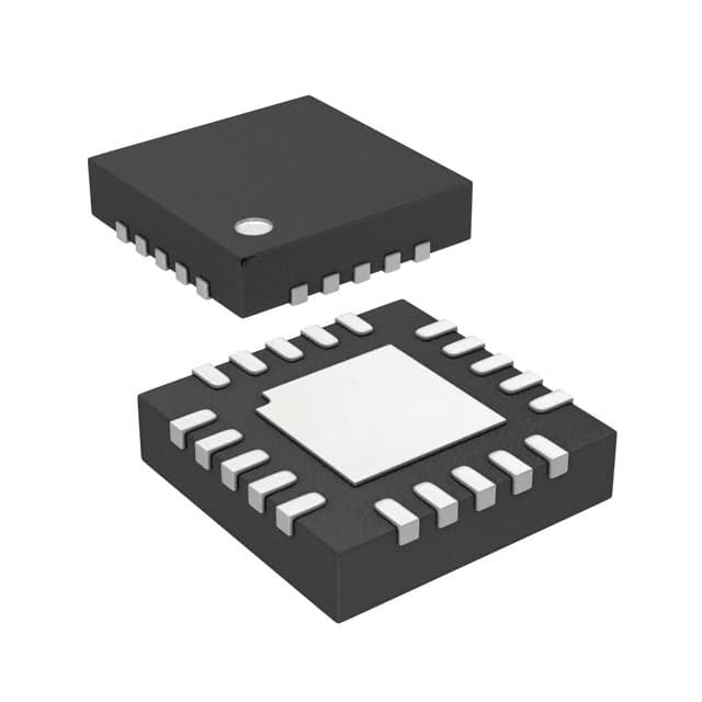
- Part No.:
- LTC3219EUD#PBF
- Manufacturer:
- Analog Devices Inc.
- Category:
- LED Drivers
- Package:
- 20-WFQFN Exposed Pad
- Datasheet:
-
 LTC3219EUD#PBF.pdf
- Description:
- IC LED DRVR RGLTR I2C 28MA 20QFN
- Quantity:
- Payment:

- Shipping:

Inventory:6,767
Please send an inquiry. Send us your inquiry, and we will respond immediately.
Product details
Overview
LTC3219EUD#PBF from Analog Devices (formerly Linear Technology) is a 9-channel universal LED driver IC with integrated multimode charge pump, delivering up to 250mA total output current across nine independent 28mA current sources. It features 6-bit linear DAC brightness control, I²C-based independent on/off, blinking, and gradation per channel, and operates from 2.9V to 5.5V VBAT for QVGA+ display backlighting in video phones.
For engineers reviewing the LTC3219EUD#PBF datasheet, LTC3219EUD#PBF pinout, LTC3219EUD#PBF application, or LTC3219EUD#PBF equivalent, this page provides verified technical context, real-world design meaning of key specs, validated pin functions, confirmed alternative parts with documented functional differences, and supply-ready availability details - all grounded in the official LTC3219 datasheet (3219fa) and Linear/Analog Devices product documentation.
Technical Context
The LTC3219EUD#PBF implements an adaptive switched-capacitor charge pump with automatic 1x → 1.5x → 2x mode switching triggered by LED current source dropout detection, optimizing efficiency up to 91% while minimizing EMI via slew-limited flying capacitor switching at 850kHz. Each of the nine ULED outputs supports 64-step linear current control (0–28mA), independent blink timing (1.25s/2.5s period), and gradation ramp times (0.24s/0.48s/0.96s).
It uses a 2-wire I²C interface (400kHz max, slave address 0x36) with register-mapped control (REG0–REG11), supports external asynchronous enable via ENU pin, and integrates internal soft-start, thermal/short-circuit protection, and DVCC-referenced digital I/O. The device resets to 1x mode on I²C register update, ENU falling edge, or gradation completion.
Key Specifications
| Parameter | Value and Actual Design Meaning |
|---|---|
| Output Channels | Nine independent universal LED current sources (ULED1–ULED9), each configurable as constant-current sink or open-drain GPO. |
| Max Total Output Current | 250mA - enables simultaneous driving of multi-segment displays (e.g., 4-main + 2-sub + RGB) without external boost stages. |
| Current Range per Channel | 0–28mA in 64 linear steps - supports precise grayscale control for monochrome or RGB subpixel dimming. |
| Charge Pump Modes | Auto-switching 1x / 1.5x / 2x - maintains regulation under varying LED VF (e.g., 3.2V @ 15mA) while limiting CPO ripple and input current surge. |
| I²C Interface | Standard 2-wire, 400kHz max, fixed slave address 0x36 - enables compact microcontroller integration with no additional level-shifting required for DVCC = 1.5–5.5V. |
| Operating Voltage Range | VBAT: 2.9V–5.5V; DVCC: 1.5V–5.5V - compatible with single-cell Li-ion (3.0–4.2V) and dual-cell alkaline systems. |
| Package | 20-lead 3mm × 3mm QFN with exposed pad (Pin 21 = GND) - supports high-density layout and thermal dissipation up to 125°C junction temperature. |
Pinout & Package
20-lead (3mm × 3mm) plastic QFN package with exposed thermal pad (Pin 21 = GND). Requires soldering exposed pad to PCB ground plane for thermal and electrical integrity.
| Pin/Terminal | Circuit Role | Design Meaning |
|---|---|---|
| CPO (1) | Charge pump output | Supplies regulated voltage (1×, 1.5×, or 2× VBAT) to all ULED channels; requires 2.2μF ceramic capacitor to GND. |
| ULED1–ULED9 (2–6, 11–14) | Universal LED current sinks | Each delivers 0–28mA with 6-bit DAC control; can be reconfigured as I²C-controlled open-drain GPO outputs. |
| DVCC (7) | Digital supply reference | Sets logic threshold for SCL/SDA/ENU; powers internal registers; UVLO at 1.0V ensures safe reset on power-up. |
| SCL (8), SDA (9) | I²C serial interface | Standard 2-wire bus (slave address 0x36); DVCC-referenced inputs support mixed-voltage system interfacing. |
| ENU (10) | Asynchronous enable control | Toggles pre-selected ULEDs without I²C traffic; forces 1x mode on falling edge and enables wake-on-call functionality. |
| GND (15, 21) | System ground | Pins 15 and 21 (exposed pad) must both connect to PCB ground plane for EMI suppression and thermal management. |
| C1P/C1M/C2P/C2M (16–20) | Flying capacitor terminals | Connect two 1μF X5R/X7R ceramics (C1P–C1M, C2P–C2M) - critical for charge pump efficiency and low-noise operation. |
| VBAT (18) | Main power input | Supplies entire IC; requires 2.2μF low-ESR ceramic bypass capacitor; UVLO at 1.5V prevents erratic startup. |
Key Features
| Feature | Design Value |
|---|---|
| Multimode charge pump | Automatically selects 1x/1.5x/2x based on real-time ULED dropout - eliminates manual mode selection and maximizes efficiency across varying LED forward voltages. |
| Slew-limited switching | Controlled dV/dt on C1P/C1M/C2P/C2M pins reduces conducted/radiated EMI - meets Class B emissions without shielding or ferrites in handheld designs. |
| Independent per-channel control | Full I²C programmability of on/off, 64-step brightness, blink period (1.25s/2.5s), and gradation ramp time (0.24s/0.48s/0.96s) - enables dynamic UI effects without MCU intervention. |
| Configurable ENU pin | Hardware-toggled enable for pre-programmed ULED subsets - allows low-power wake-up (e.g., incoming call indicator) without waking host processor or reinitializing I²C. |
| Internal soft-start | Linear CPO current ramp over ~125μs during mode transitions - prevents input supply droop and inrush current spikes that could reset co-located circuits. |
Applications
| Video Phone Backlighting | Portable Medical Display |
|---|---|
Use Scenario: Driving QVGA+ main display (4 LEDs), sub-display (2 LEDs), and RGB status indicator in battery-powered video phones. IC Role / Device Role / Timing Role: Universal LED driver with integrated charge pump and I²C-controlled gradation - replaces discrete boost + current sink solutions. Use Value: Enables smooth brightness transitions and synchronized blink effects across heterogeneous displays using one compact IC and five ceramic caps. |
Use Scenario: Powering high-contrast monochrome LCD backlight and status LEDs in portable ultrasound or patient monitor devices. IC Role / Device Role / Timing Role: Precision current source with 2% matching and 0.51mA minimum step - ensures consistent luminance across clinical-grade displays. Use Value: Meets stringent EMC requirements via slew-limited charge pump, eliminating need for external EMI filters in certified medical hardware. |
| Industrial HMI Panel | Smart Wearable Indicator |
Use Scenario: Controlling segmented backlight and alert LEDs on ruggedized human-machine interface panels operating from 3.3V or 5V rails. IC Role / Device Role / Timing Role: Multichannel current driver with ENU-triggered wake-up - supports instant visual feedback without MCU polling. Use Value: Reduces BOM count by integrating nine current sources, charge pump, and I²C interface - simplifies layout and improves long-term reliability. |
Use Scenario: Managing ultra-low-power RGB status lighting and haptic feedback indicators in hearables or smartwatches with tight space constraints. IC Role / Device Role / Timing Role: Low-quiescent I²C slave (1μA DVCC shutdown) with 3mm × 3mm QFN footprint - minimizes PCB area and battery drain. Use Value: Delivers 250mA peak drive within 9mm² footprint while maintaining <3.2μA VBAT shutdown current - extends coin-cell battery life by months. |
Equivalent & Alternatives
The following parts are listed as comparable options for similar LED driver applications.
| Alternative Part | Technical Difference | Application Difference | Selection Advice |
|---|---|---|---|
| MAX16823ATL+T | 4-channel, 120mA total, no integrated charge pump - requires external boost converter; I²C interface with 10-bit DAC resolution. | Targeted at automotive interior lighting with AEC-Q100 qualification; lacks gradation/blink engine and ENU pin. | Select when AEC-Q100 compliance and higher DAC resolution are required, but accept larger solution size and loss of autonomous UI effects. |
| TPS61165DRVR | Single-output, 40mA max, integrated boost converter with PWM dimming only - no I²C, no multi-channel support, no gradation. | Optimized for single-white-LED flashlight or camera flash; lacks per-channel control and multimode efficiency optimization. | Select for cost-sensitive, single-LED applications where I²C programmability and multi-segment control are unnecessary. |
Compared with MAX16823ATL+T and TPS61165DRVR, the LTC3219EUD#PBF uniquely integrates nine independent current sources, adaptive charge pump modes, and full I²C-based gradation/blinking - enabling complex, low-EMI display lighting in space-constrained portable electronics without external components or firmware overhead.
Availability
LTC3219EUD#PBF is available at Aetrix Electronics and suitable for video phone backlighting, portable medical display illumination, and industrial HMI panel lighting requiring stable component supply, long-term lifecycle support, and RoHS-compliant lead-free packaging.
Supply support for LTC3219EUD#PBF includes scheduled delivery planning, volume procurement assistance, BOM continuity management, traceable sourcing, and lifecycle availability coordination for OEM customers, industrial embedded developers, connected-device designers, and electronics production programs.
Manufacturer
Analog Devices, Inc. (ADI) acquired Linear Technology in 2017 and maintains full product support, datasheets, and application notes for the LTC portfolio. ADI is a global leader in high-performance analog, mixed-signal, and power management semiconductors.
The LTC3219 belongs to Linear's precision LED driver product line, designed specifically for space-constrained portable electronics requiring high-efficiency, low-noise, multi-channel display lighting with autonomous visual effects - not general-purpose power conversion.
FAQ
What is the maximum total output current supported by the LTC3219EUD#PBF?
The LTC3219EUD#PBF supports up to 250mA total output current across its nine ULED channels. This is achieved with each channel delivering up to 28mA (typical full-scale), allowing flexible allocation - for example, 4 main display LEDs at 25mA each, 2 sub-display LEDs at 20mA each, and 3 RGB LEDs at 15mA each totals 230mA, staying within the 250mA limit. The LTC3219EUD#PBF datasheet confirms this rating under typical conditions with proper capacitor selection and thermal management.
Does the LTC3219EUD#PBF require external components to operate?
Yes, the LTC3219EUD#PBF requires five external ceramic capacitors: one 2.2μF (C1/C4) on VBAT and CPO, two 1μF (C2/C3) flying capacitors on C1P/C1M and C2P/C2M, and one 0.1μF (C4) on DVCC. These are mandatory for charge pump operation, noise reduction, and digital supply decoupling. No inductors or external MOSFETs are needed - the LTC3219EUD#PBF integrates all power switches and control logic internally.
Can the LTC3219EUD#PBF drive RGB LEDs independently?
Yes, the LTC3219EUD#PBF can drive RGB LEDs independently using three of its nine ULED channels (e.g., ULED7, ULED8, ULED9), each with full 6-bit linear DAC control (0–28mA), independent blink timing, and gradation ramping. Its I²C interface allows per-channel current programming and synchronization - enabling true RGB color mixing and dynamic effects without additional controllers. This capability is explicitly validated in the LTC3219EUD#PBF typical application circuit (TA01a) showing RGB configuration.
What is the function of the ENU pin on the LTC3219EUD#PBF?
The ENU pin on the LTC3219EUD#PBF provides hardware-level asynchronous enable/disable control for pre-configured ULED subsets - for example, activating only status LEDs during an incoming call without waking the host MCU or reissuing I²C commands. When toggled high, it illuminates selected outputs; on falling edge, it resets the charge pump to 1x mode and can trigger shutdown if no other ULEDs are active. The LTC3219EUD#PBF datasheet specifies ENU logic levels relative to DVCC and mandates grounding if unused.
Is the LTC3219EUD#PBF pin-compatible with other Linear LED drivers?
No, the LTC3219EUD#PBF is not pin-compatible with other Linear/Analog Devices LED drivers such as the LTC3206 or LTC3215. Its 20-pin 3mm × 3mm QFN layout, pin assignments (e.g., dual flying capacitor pairs, dedicated ENU, nine ULED outputs), and internal register map are unique to the LTC3219 family. Substitution requires PCB redesign and firmware adaptation - the LTC3219EUD#PBF datasheet contains no cross-reference or migration path to alternate packages.
LTC3219EUD#PBF Specifications
- Product attributes
- Attribute value
- Manufacturer:
- Analog Devices Inc.
- Series:
- -
- Package/Case:
- 20-WFQFN Exposed Pad
- Packaging:
- Tube
- Product Status:
- Active
- Type:
- DC DC Regulator
- Topology:
- Switched Capacitor (Charge Pump)
- Internal Switch(s):
- Yes
- Number of Outputs:
- 9
- Voltage - Supply (Min):
- 2.9V
- Voltage - Supply (Max):
- 5.5V
- Voltage - Output:
- -
- Current - Output / Channel:
- 28mA
- Frequency:
- 850kHz
- Dimming:
- I2C
- Applications:
- -
- Operating Temperature:
- -40°C ~ 85°C (TA)
- Grade:
- -
- Qualification:
- -
- Mounting Type:
- Surface Mount
- Supplier Device Package:
- 20-QFN (3x3)
LTC3219EUD#PBF FAQ
1.How can I place an order for LTC3219EUD#PBF through Aetrix?
Please submit a Request for Quotation (RFQ) for LTC3219EUD#PBF on Aetrix. Our sales agent will provide a competitive quotation and guide you through the order confirmation once you accept the terms.
2.Are the price and stock information for LTC3219EUD#PBF reliable?
The price and inventory of LTC3219EUD#PBF are updated periodically and may fluctuate due to market conditions. Stock and pricing data are typically refreshed every 24 hours. Quotation validity for LTC3219EUD#PBF is usually 5 days.
3.What payment methods are accepted for LTC3219EUD#PBF?
We accept Wire Transfer, PayPal, Credit Card, Western Union, MoneyGram, and Escrow for LTC3219EUD#PBF transactions.
Note: Certain payment methods may incur a processing fee.
4.How is shipping managed for LTC3219EUD#PBF?
LTC3219EUD#PBF orders can be shipped via leading logistics carriers, including DHL, UPS, FedEx, TNT, or Registered Mail.
Once your LTC3219EUD#PBF order is processed, you will receive an email with the shipment details and tracking number.
Note: Tracking information may take up to 24 hours to appear. Express delivery typically takes 3–5 business days.
5.How can I obtain technical support or documentation for LTC3219EUD#PBF?
For technical support, including LTC3219EUD#PBF datasheets, pinout diagrams, or application guidance, please contact our engineering support team. They can provide detailed documentation and assistance for your LTC3219EUD#PBF requirements.
6.How does Aetrix verify that LTC3219EUD#PBF is sourced from the original manufacturer or authorized distributors?
All LTC3219EUD#PBF products on Aetrix are procured from qualified distributors and authorized channels. Our dedicated quality assurance team conducts strict verification, including traceability checks and, if necessary, third-party testing. This ensures that LTC3219EUD#PBF meets industry standards.
7.What is the process for return or replacement of LTC3219EUD#PBF?
All LTC3219EUD#PBF units undergo pre-shipment inspection (PSI). If there is an issue with LTC3219EUD#PBF, returns or replacements are accepted under the following conditions:
1.Quantity discrepancies, incorrect items, or visible external defects (such as breakage or corrosion), acknowledged by Aetrix.
2.The issue is reported within 90 days of delivery.
3.The LTC3219EUD#PBF part is unused and in its original packaging.
Return procedure for LTC3219EUD#PBF:
1.Submit a request within 90 days.
2.Obtain a Return Material Authorization (RMA) from Aetrix.
LTC3219EUD#PBF Tags

-
BCR402RE6327HTSA1
Infineon Technologies

-
BCR430UXTSA2
Infineon Technologies

-
BCR420UE6433HTMA1
Infineon Technologies
-
BCR420UE6327HTSA1
Infineon Technologies
-
BCR421UE6327HTSA1
Infineon Technologies

-
LYT1604D-TL
Power Integrations

-
HV9910CLG-G
Microchip Technology

-
CL2N8-G
Microchip Technology

-
BCR420UW6-7
Diodes Incorporated
-
BCR421UW6-7
Diodes Incorporated

-
BCR420UFD-7
Diodes Incorporated
-
BCR421UFD-7
Diodes Incorporated
Tech Hub

A practical engineering guide to 3.3V and 5V logic compatibility, input thresholds, resistor dividers, translator ICs, MOSFET level shifting, I2C pull-ups, timing limits and power-sequencing risks.

The 74HC595 uses push-pull logic outputs, while the TPIC6B595 uses 50 V open-drain DMOS sinks for higher-power loads. This guide compares timing, current limits, 3.3 V interfacing, load wiring, thermal…

The 74HC595 converts serial data into eight stable parallel outputs. This guide covers pin functions, shift and storage timing, OE and MR behavior, drive-current limits, cascading, voltage compatibilit…

A technical comparison of level-sensitive latches and edge-triggered flip-flops, covering timing windows, setup and hold limits, master–slave operation, time borrowing, race-through, HDL inference and…

A D latch stores one bit while Enable controls when data can pass. This reference covers gate-level operation, truth tables, transparency, setup and hold timing, LE versus OE, common ICs and practical …

An SR latch stores one bit through cross-coupled feedback. This engineering reference covers NOR and NAND implementations, truth tables, forbidden-state recovery, gated operation, switch debouncing, fa…

Latch circuits retain one bit through feedback. This technical reference covers SR and D latches, truth tables, transparency, timing limits, latch-versus-flip-flop behavior, applications and common log…

An engineering guide to LED driver operation, constant-current and constant-voltage outputs, linear and switching topologies, dimming, IC selection, calculations, replacement compatibility, and fault c…

Operational amplifier guide covering op amp basics, feedback, ideal vs real op amps, common configurations, buffer circuits, offset, bias current, gain-bandwidth, slew rate, rail-to-rail limits and sel…

Jumper cables guide covering safe connection order, red and black clamp placement, final ground connection, cable gauge, length, clamp quality, copper vs CCA cables, jump starter comparison and battery…


